Chuck
-
Posts
9,703 -
Joined
-
Last visited
Content Type
Profiles
Forums
Gallery
Events
Everything posted by Chuck
-
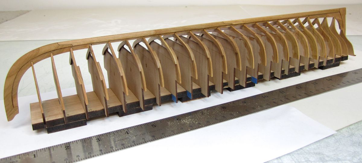
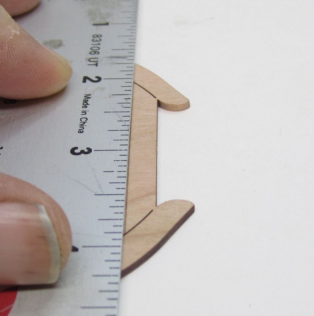
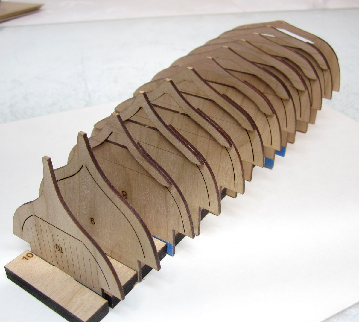
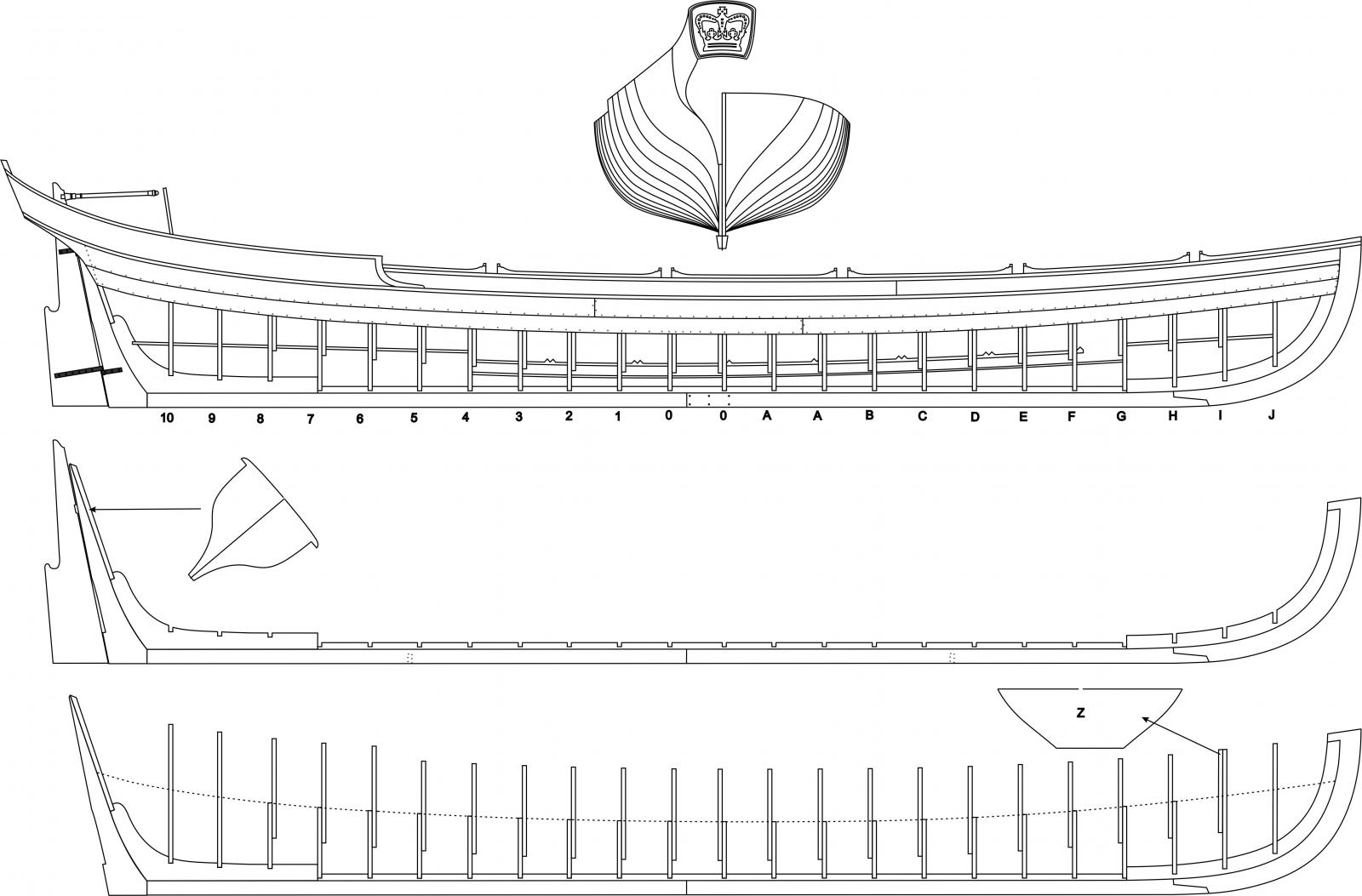
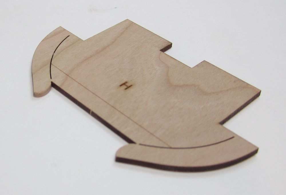
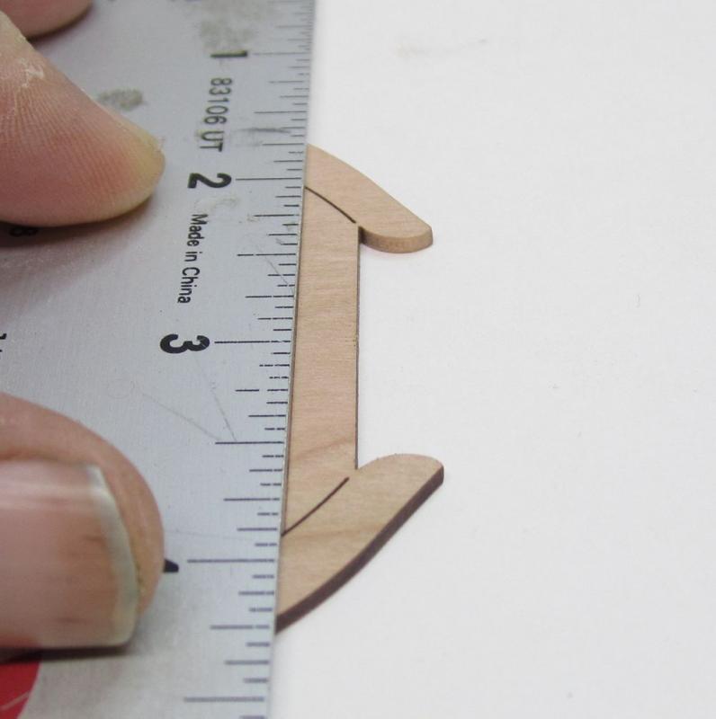
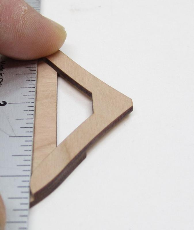
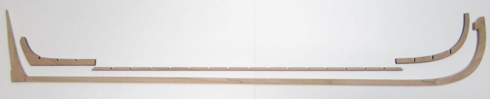
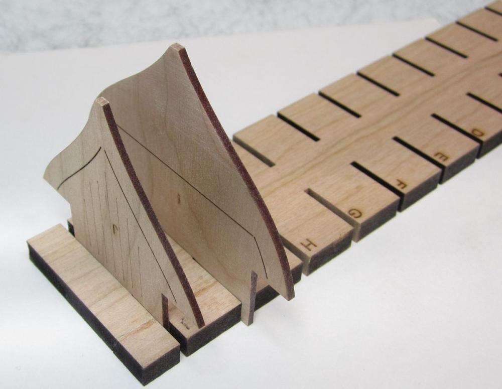
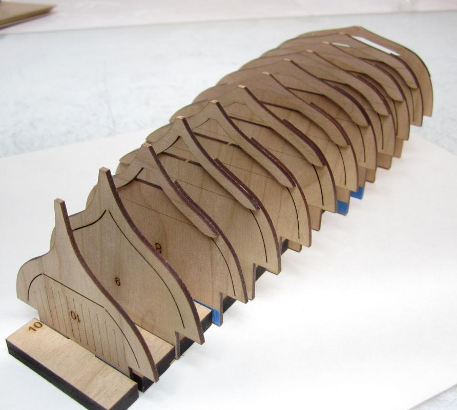
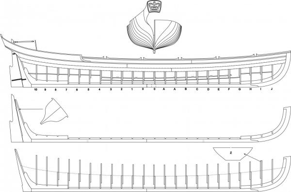
 Thank you all for the well wishes and questions Just to answer a few questions I have received about this Royal Barge. - It is circa 1700 - Queen Anne Style Royal Barge - It WILL be a full Kit and not a scratch/with some laser cut parts. My first full kit with everything all included. - It is 1:24 scale and will be about 20" long. -The stock kit will be made in Cherry with boxwood carvings and trim in place of gilding. A boxwood or Pear upgrade version will also be made available as special order. But the cherry will look great and be far less expensive. I am using prime pieces that are "cherry-picked" for a lighter tone. Examine the image below and look at how much waste wood there would be on each frame if Boxwood or pear was used...each kit in those woods will be considerably more expensive and mostly used up for the frame centers. So consider this if you intend to order a custom cut version in Box or Pear. - The build board....for lack of a better word is included. Its a design choice to replace of all of those pesky wood strips people glue across the frames for the longboat and pinnace to stabalize it for fairing and planking. I have learned a lot watching all of you build those. This replaces the need for those and provides a sturdy base to Clinker plank....only three strakes will be on each kit to mirror the contemporary examples we are all familiar with. They will be pre-spiled and laser cut to make it easier. - The vertical lines shown on frames "10" and "J" in the previous post are there as a visual reference. They are there so when you place the keel assembly on top of the frames.... you can eyeball the hull from dead astern and at the bow to make sure its straight and not tilted one way or the other. Its a slightly different build concept than placing the frames into the keel slots first like the longboat. The build-board lines them all up so you dont have to fight with trying to get them all centered and perpendicular....those that built the pinnace and longboat know what I am referencing. It was a pain to do well and there are many many more frames in this kit. It has proven more effective to place the keel onto the frames afterwards..... - I dont have any idea of price yet because its too soon in the prototype process to tell. Thanks for the interest and its OK to ask the questions in this topic....I am sure many others have the same questions and its easier to answer them once here. Thanks again Chuck
- 269 replies
-
- 34
-

-
- Queen Anne Barge
- Syren Ship Model Company
- (and 1 more)
-
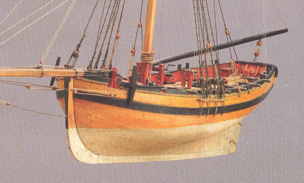
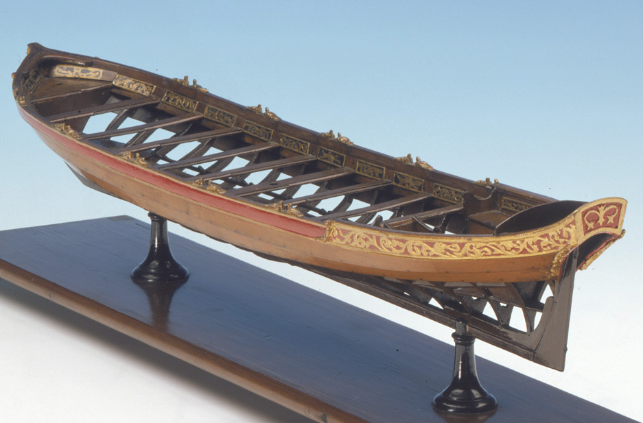
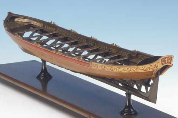
I thought I would give a little status update on this side project. As some of you know I am working on two new complete kits for Syren... One is of a 1/2" scale Royal navy barge circa 1700. I am trying to push the envelope a bit with my design concepts and the laser cutter. It will look like the contemporary model below but actually be almost exactly like the Queen Anne style barge shown in the Kriegstein collection. Those that have the Seawatch book should check it out. This will be a fully framed little model and I am very excited about it. I am building off of the design concept I used for the long boat and pinnace but taking it a bit farther. I hope these photos will give you a sufficient idea about the scope/concept of the project. This is a big barge model at over 20" long. I am fortunate to have found someone who is an excellent model builder who will build the prototype for me as it is designed. Unfortunately there is just not enough time in the day for me to build everything I design. He will be starting a build log shortly as I get a little further with the design. Many of you know him and will enjoy his build log as you have enjoyed his others. This project is a long, long way from being released but I thought I would show you what we are working on in addition to the many other projects. It also shows you how Syren will bring new projects to market without having to wait for me to build the entire model. I will be concentrating on finishing the Cheerful and then continuing with the Winchelsea. At the same time I will be collaborating with others to bring you folks additional stuff!!! There are no deadlines for these projects...they will get done when they get done. It is more important that these projects are the best possible within my limits of experience and expertise and they will never be rushed to market. I will however keep you guys updated. The last thing the hobby needs are more sub-par ship model projects and kits. I apologize for the longer development times compared to others. I hope its not too frustrating.

- 269 replies
-
- 30
-
-
- Queen Anne Barge
- Syren Ship Model Company
- (and 1 more)
-
As many of you are aware....we have had many group project forums in the past with a couple going on right now. I just closed the Longboat group which had been going for several years. It had soon run its course. All closed groups will have their logs moved to the appropriate forum. None will be lost. Keep in mind all groups are not permanent. They will wind down and close as they lose steam and participation. This will done to preserve valuable forum real estate and also keep the site fresh and exciting with new possibilities for the membership. As the administrator I will pose the question in each group forum when it looks like interest and participation crawled to a stop. It will be up to the membership if they want to keep it open...but that means its up to the membership to keep it active. If closed....All pinned topics and non logs will be moved . Nothing will be lost. To start a new project forum, it must meet this criteria. - must have 6 - 8 current members actively building the project and willing to start a log in a separate group area. Group will be open to any member wanting to participate. No exclusions. - subject can be suggested by any member as long as they meet the criteria. Its time to rally your fellow members should you wish to start one. If you are among many building one model now and there are more than 6 - 8 logs already started, why not take the initiative to contact them to see if all of you want to start a group. Just an idea. - the forums must contain only Build logs following the same guidelines for naming them as the other build log forums. -all non-build log specific info related to the project that will help the group of builders, will be posted as a pinned topic above the build logs by a moderator. -Every group project must have a named leader/mentor who will take charge of the group and agree to moderate it. If you can not find one please contact us and we will try and find one for you. If you would like to suggest a topic for such a group build area...you may list it in this forum.....Try to rally your fellow members to start and participate in a new group.....or if there are already more than 6-8 "scratch" or "kit" forum build logs started and you can convince those builders to move their topics here.....we can do that as well. But if that happens.....we will move all similar build logs here for convenience and consistency....even if you are NOT among the 6-8 who want to start such a separate group project forum. But PLEASE...be as detailed as you can when suggesting a new group be started. List the name and type of ship or item.....scratch or kit......POF or POB....solid hull....what will cost....time frame....where to get plans....kit...or supplies. What would the goal and aim be if any for the project you are trying to start. JUST ONE MORE SUGGESTION.....The project DOES NOT need to be for a complete ship or boat. For example. If members wanted to start a group about making a ship's stove or a capstan....that is fine too. As long as there are 6-8 members who are actively doing so. Trying new techniques and sharing them as well as working on the same exact thing.....if you want to start a group about using a lathe to turn cannon and it will active participants...that is great and worthwhile. A group project such as this....its about learning together and exchanging ideas as a group on any one subject. This structure is offered to make it easier and more convenient. So think outside the box. But we need 6-8 members to start one. And the key word is ACTIVE PROJECT. Chuck (MSW admin)
- 29 replies
-
- 15
-
-
Thats looking very good. It will make an excellent model!!! Well Done
- 504 replies
-
- 4
-
-
- washington
- galley
- (and 1 more)
-
Your deck looks fantastic Rusty....well done. Dont stay away for too long.
- 310 replies
-
- 4
-
-
- cheerful
- Syren Ship Model Company
- (and 1 more)
-
HM Cutter Cheerful 1806 by Erik W - 1:48 scale
Chuck replied to Erik W's topic in - Build logs for subjects built 1801 - 1850
Tat looks very good. Well done!!! -
Treenail detail option?
Chuck replied to S.Coleman's topic in Building, Framing, Planking and plating a ships hull and deck
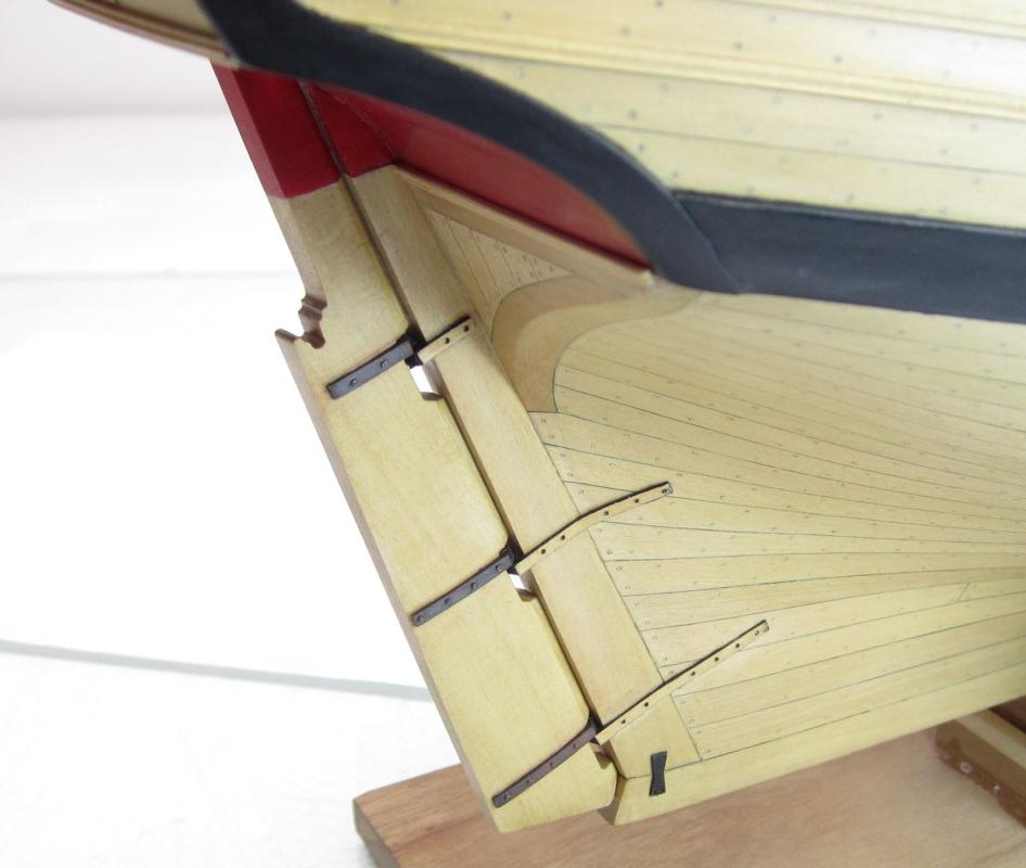
Allan Its a weird thing but it is always shown on models of the Mary Rose. Here is a bassett- lowke model of the Mary Rose and you can see the same batten type strakes along the bottom of the hull. Its very weird. -
Yes.....its digital. Chuck
-
Nope.....just wanted to have some inspiration close at hand. I try to surround myself with it and often commission other ship model builders or buy their work ..... at least when the admiral is also smitten with a particular work or subject. Chuck
-
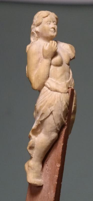
I can take as many photos of her as you would like...just let me know when you are ready. Here is an in-progress photo....this depiction is much like the one shown on the NMM model and the original draft which shows the figurehead. Its is exactly like the detail shown on that original draft. Plans during the 1770's often had incredible detail with all of the carvings and even friezes shown in many instances. It is a very accurate depiction.
-
Beautiful work.....just wonderful to look at and would look at home on anyone's desk....the perfect gift!!!! Hint!!! Hint!!!
- 641 replies
-
- 12
-
-
- greenwich hospital
- barge
- (and 1 more)
-
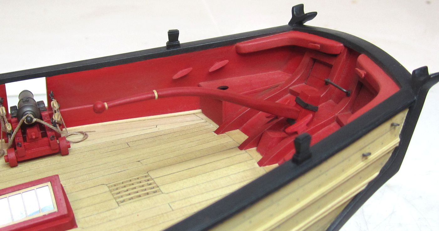
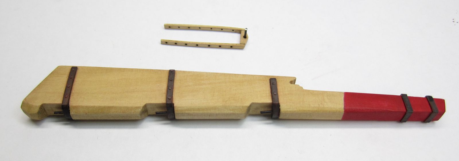
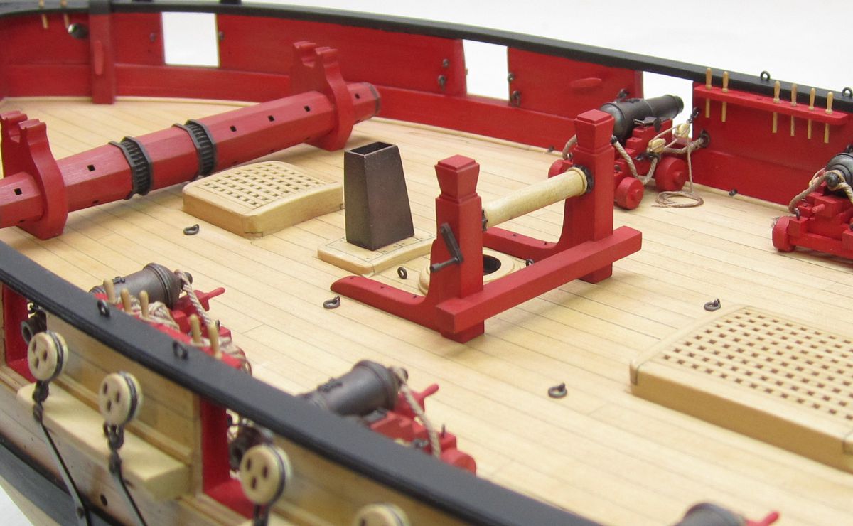
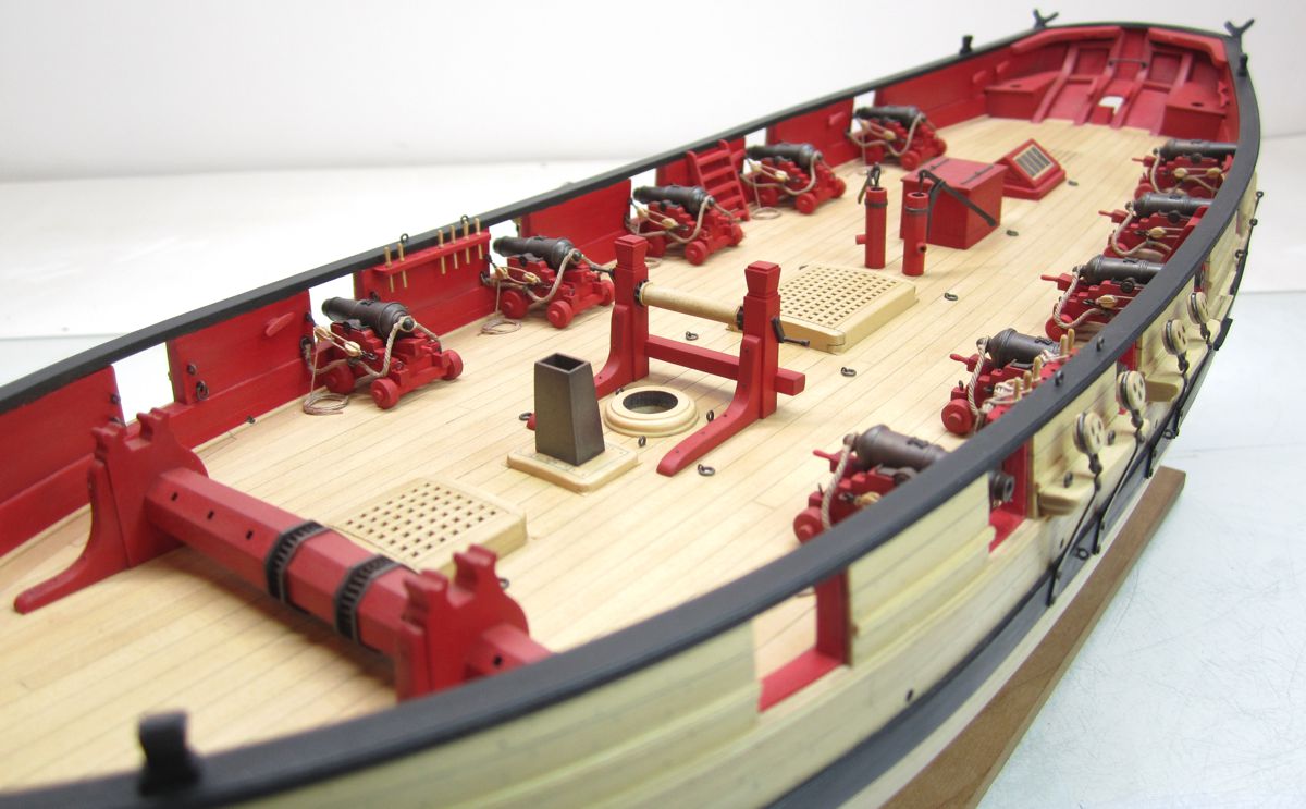
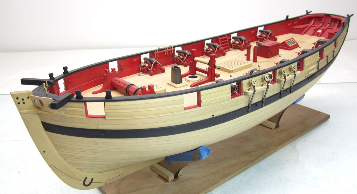
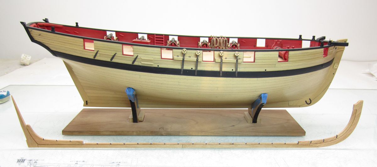
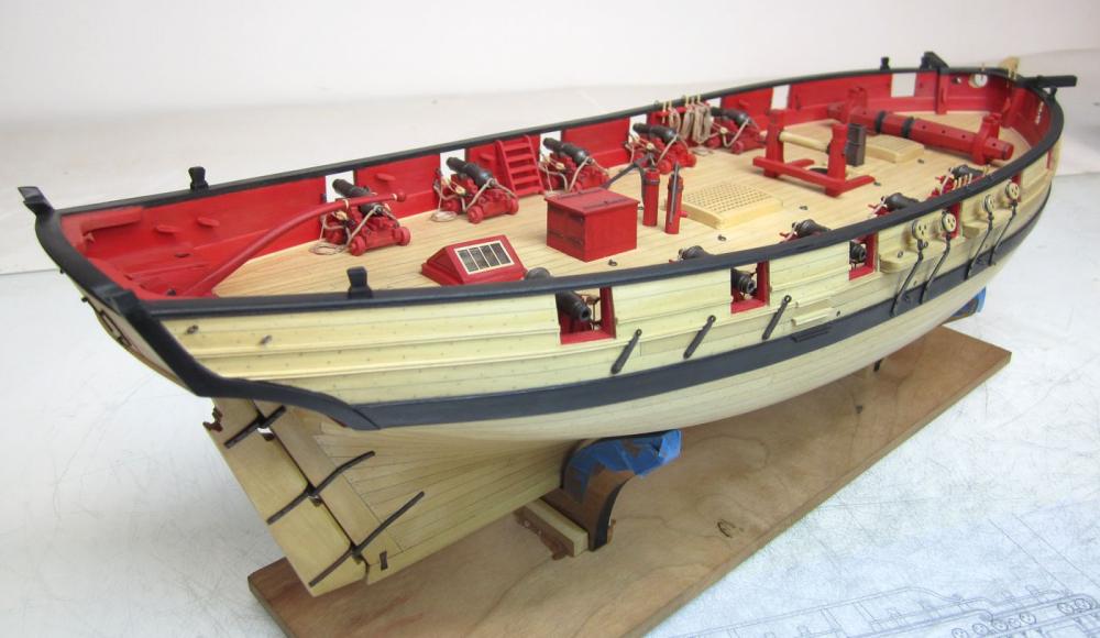
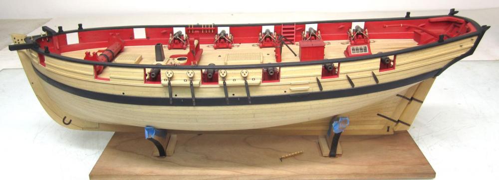
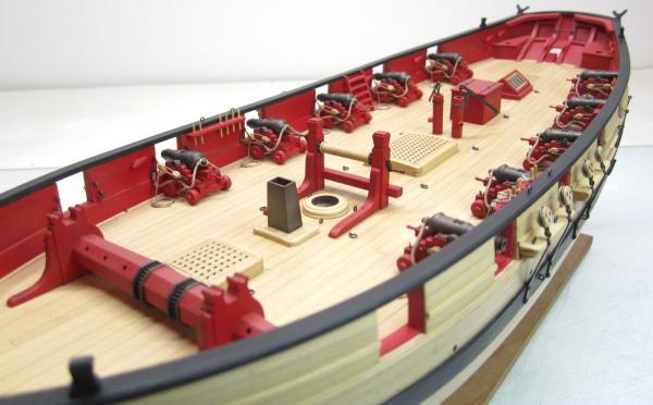
Just completed the tiller after mounting the rudder. It was cut from a 1/8" thick sheet of boxwood. Then it was carefully rounded off and shaped using files and sanding sticks. I could have left it natural but it just looked to bright and "blah" looking. So I painted it red and highlighted the parts of the handle on tiller. I like this much better. I am sure everyone has their preference but I have also seen the tiller painted black on contemporary models. I dont think I would have liked it like that. Next up I will be making the bowsprit. Here are some overall shots with the deck almost completed except for the bowsprit bits and bow chasers. Chuck

- 1,051 replies
-
- 39
-
-
- cheerful
- Syren Ship Model Company
- (and 1 more)
-
No rotary....just sharp chisels. Various styles...."V" shaped and flat etc.....and VERY SHARP.
-
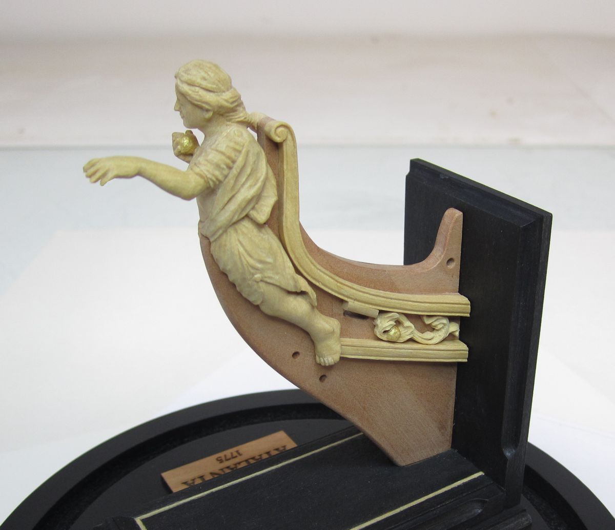
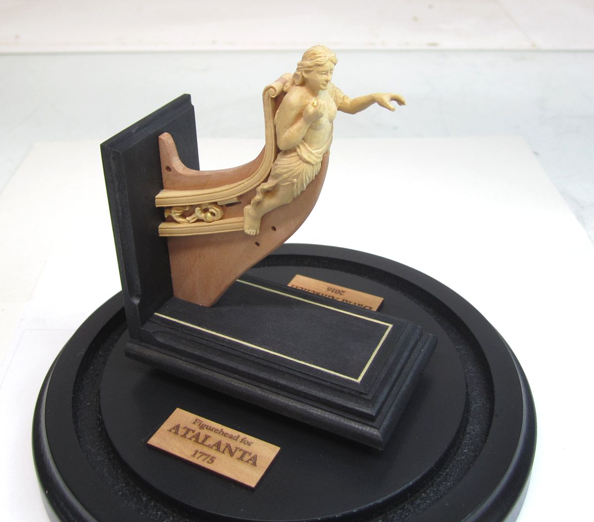
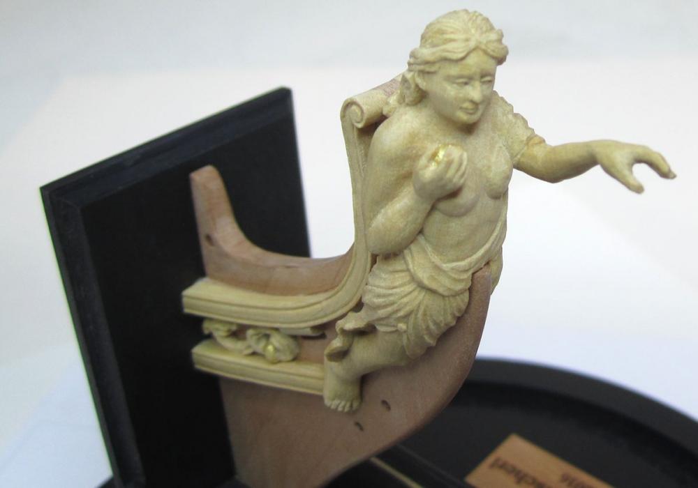
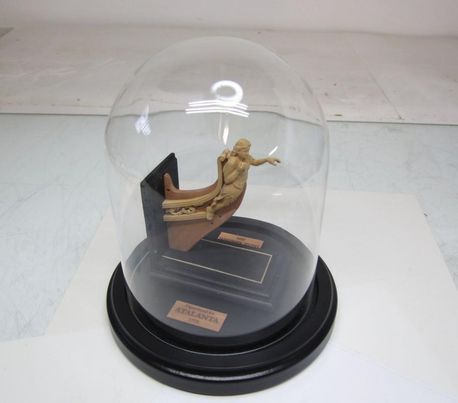
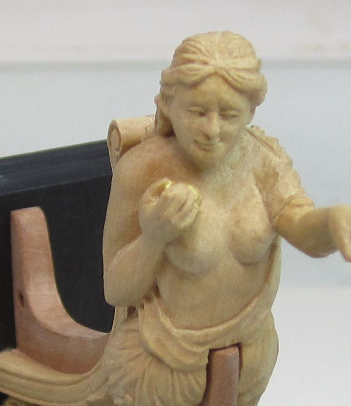
Just thought I would share these incredible pictures of the figurehead for the Swan Class Sloop "Atalanta" by David Antscherl. The figure is boxwood with a stem of swiss pear. The brackets and trailboard carving are also boxwood. Note the gold leafed apples. Just stunning carving by hand and almost hard to believe possible at this scale. Its so tiny. I love the facial expression.....Mona Lisa smirk... Enjoy!!! The glass dome is just 4" in diameter. Chuck


-
That looks wonderful. They will look great on the model presentation. Chuck
- 641 replies
-
- 8
-
-
- greenwich hospital
- barge
- (and 1 more)
-
Very nicely done.... Jeez even you are catching up with me now Rusty.....work more on the house...LOL
- 310 replies
-
- 8
-
-
- cheerful
- Syren Ship Model Company
- (and 1 more)
-
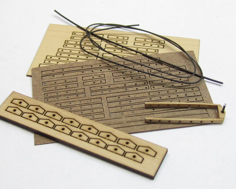
Completed the rudder today. As you see, I created an alternative for fabricating metal gudgeons and pintels. I dont have the tools to solder brass versions and I hate working in metal. So I made mine from wood. I also made a version using laserboard for the straps. It worked just as well. These are very sturdy rudder hinges. They are three pieces. All laser cut. The center is sanded to the width of the stern post and rudder. Then the straps are added after being cut to length. They are pre-cut with holes. 24 gauge wire was inserted into those holes after drilling them a bit deeper into the rudder. Then the wire was pushed into the holes and snipped off. It was snipped off so the end would stand proud of the straps by just a hair simulating the bolts. These laser cut "cheat hinges" did a great job in my opinion and they are so easy to work with. The straps are a bit thick originally but after gluing them on the rudder and hull they are sanded down to a really thin profile. Then they are painted black after the wire is inserted into all of the holes. For the "hinge pin" a small length of 22 gauge wire was used. It was glued into the hole in the center section of this mini-kit. As a tip for those who will start fabricating theirs out of wood....paint the edges of the straps black ahead of time and you will have a nice neat edge. You can see the ones on my hull which havent been completed yet. I still have to add the simulated bolts with wire. They are unpainted. Once this is done I will create the tiller. AND YES...before anyone asks these are now available as a stock item . Not just for cheerful as they worked out so well I am sure others will want them. The straps and center are 1/16" wide which is a typical size and could be used for many other models. Both laserboard and boxwood straps will be included in each package. Choose whatever you prefer. Why havent these ever been made before??? They are wonderful if I dont mind saying myself. And they are so simple. Click Here to see them.
- 1,051 replies
-
- 48
-
-
- cheerful
- Syren Ship Model Company
- (and 1 more)
-
Just like a windlass there were small pawls on the inside of the uprights that would engage the sprockets. But they are rarely shown on models. Its up to the builder to decide if they want to include them. They are usually on the aft side of the uprights....BUT like everything else there are so many variations. I just picked one from a contemporary model. I believe it was a variation of the one shown on the Surly model in the Thompson Collection. See below for a few including the Surly model. Chuck

- 1,051 replies
-
- 14
-
-
- cheerful
- Syren Ship Model Company
- (and 1 more)
-
Thats the windlass. The winch will be a mini-kit too. Probably in a week or so. Its easy to build from scratch but the small gears are better to have laser cut. They are a pain to make by hand. I will cut about a dozen of them sometime next week. Chuck
- 1,051 replies
-
- 5
-
-
- cheerful
- Syren Ship Model Company
- (and 1 more)
-
Thank You.....I just finished making the winch. This is a pretty straight forward fitting. The pieces were cut taking the measurements from the plans. Nothing was to difficult but care was taken to make the winch handles look more attractive than just using a piece of black wire. So I cut some micro tube to slip over the end of the handle to give it some dimension. This is the last deck fitting before the rigging prep starts. I will finish the rudder and tiller first however. Then there is the bowsprit bitts up front which also contain the pawl for the windlass. But I would like to have the bowsprit made while making that. Once thats finished I will add the two long guns at the bow...... That is everything that is left before the rigging begins so I feel like I am getting into the home-stretch. Chuck


- 1,051 replies
-
- 41
-
-
- cheerful
- Syren Ship Model Company
- (and 1 more)
-
Well.....that would probably be right on the line of of copyright issues.... BUT, if you guys can wait a bit, I plan on coming out with a 1/2" scale version of a longboat kit that is a bit more advanced. The shallop is being done first however. It will be framed similar but with both futtocks and floors like a contemporary model. Plus after learning a bit more and tweaking the design concept somewhat, many other improvements were made. Its basically taking the design concept to the next level.
- 162 replies
-
- 6
-
-
- 18th century longboat
- model shipways
- (and 1 more)
-
Indeed that is awful laser cutting. With Basswood the kerf should be very very thin......not much power is needed to cut through that stuff as it is only 1/16" thick. Too bad.
- 162 replies
-
- 4
-
-
- 18th century longboat
- model shipways
- (and 1 more)
-
Yes....she will basically be just like the contemporary model pictured. Chuck
- 49 replies
-
- 4
-
-
- pinnace
- Syren Ship Model Company
- (and 1 more)
-
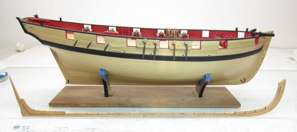
Thank you....Hopefully I will be able to show the larger barge in progress very soon....it is very similar but with more decoration. And its much larger. This one will be fully framed...you can see the keel assembly as compared to the Cheerful model.
- 49 replies
-
- 13
-
-
- pinnace
- Syren Ship Model Company
- (and 1 more)
-
It's looking fantastic Greg...You have been making a lot of progress. Good to see updates again. How about an overall shot of the hull. I would love to see her lines and sheer? Chuck