Chuck
-
Posts
9,703 -
Joined
-
Last visited
Content Type
Profiles
Forums
Gallery
Events
Everything posted by Chuck
-
 Yes....but not as easy as just clicking a button. Which most would assume. After resizing the templates in the drafting software (the easy part)....the laser settings will then have to be adjusted to reflect the proper speed and power settings for the smaller thickness in wood. Depending on the parts, they also may need some tweaking to adjust for the larger kerf size in relation to the smaller part size (ie the carved decorations). Plus the five or six more elaborate carvings are being done as resin castings. I cant expect folks to scratch carve those so masters will need to be made for those. So there are plenty of hours of work needed to do it correctly for the best results. But once its done the first time, its done and all parts can easily be run as quickly as the 1/2" scale versions. But its still weeks of work. After all that there are other considerations. This design concept works well for 1/2" scale. BUT Lets consider that the frames are 1/16" thick at this scale. Reducing them to 1/4" scale means using 1/32" thick stock. Or at a minimum, going with 3/64" for strength. I think using 1/32" thick frames for this design construction method would not work as the frames would be much to fragile. So once you start altering those thicknesses...it means more alterations for the parts templates and it just snowballs from there. To simply reduce everything by 50% without thinking it through would be a disaster. I know some other folks think its easily done and have talked about it in other threads. In my opinion its not as simple and a bit fantasy actually. Depending on the subject of course. Decisions would need to be made that may reduce its historical accuracy for MFG purposes or depending on the scale, a entirely different construction concept might be a better way to go. Lots to consider. I hate to be the fantasy killer to all those folks discussing the possibilities of kit production in that other topic. But its a little naive in my opinion. For most subjects anyway.
- 269 replies
-
- 13
-

-
- Queen Anne Barge
- Syren Ship Model Company
- (and 1 more)
-
Nope. Just the kit. Either in installments or as one complete unit. The plans will of course be in the first installment along with the frames, keel parts and build-board. Chuck
- 269 replies
-
- 6
-
-
- Queen Anne Barge
- Syren Ship Model Company
- (and 1 more)
-
Thank you guys. Yes an intermediate builder can do this. Those are the folks this project is directed towards. As far as making the kit in parts.....I am torn. It will either be a complete kit....OR A complete kit sold in three installments. I am trying to work all that out as the prototype gets underway. I am waiting on planking material as we speak. Once it arrives it will get into high gear. Chuck
- 269 replies
-
- 7
-
-
- Queen Anne Barge
- Syren Ship Model Company
- (and 1 more)
-
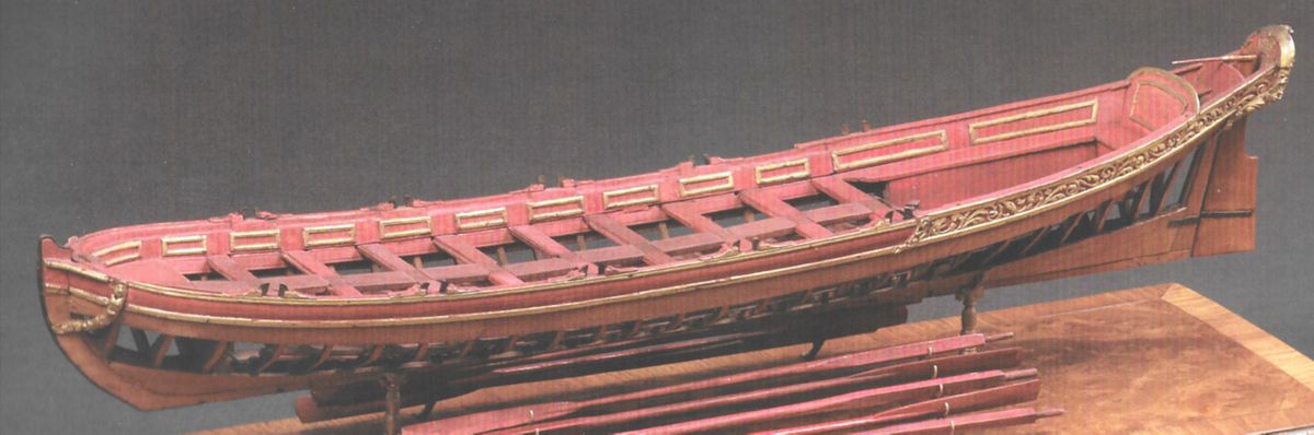
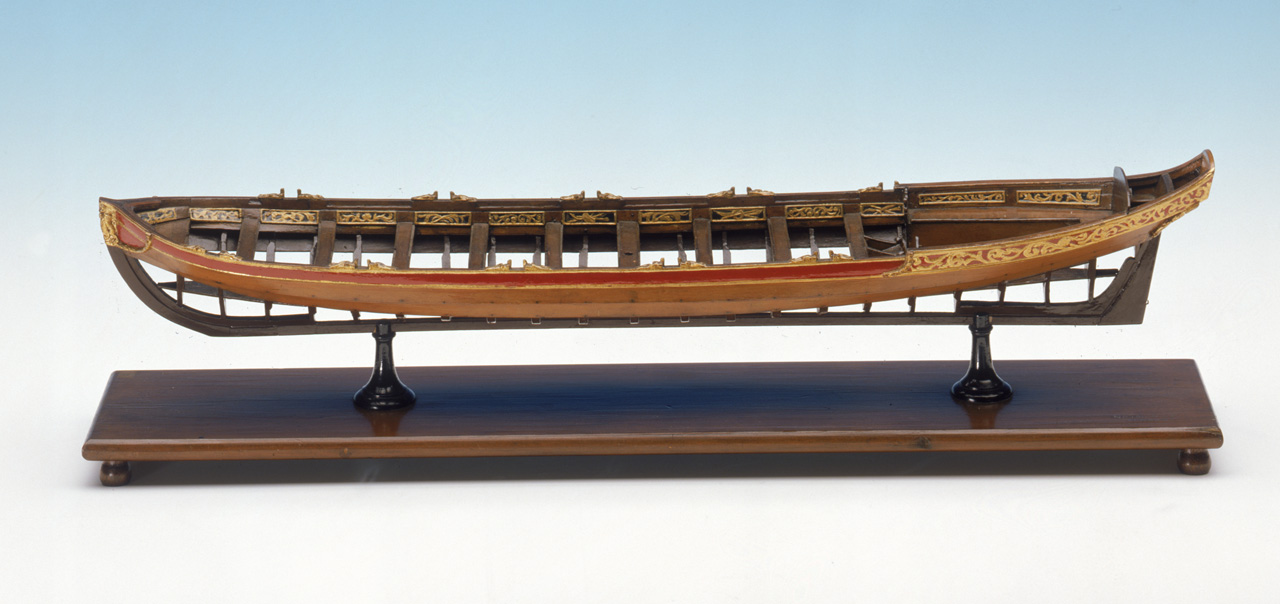
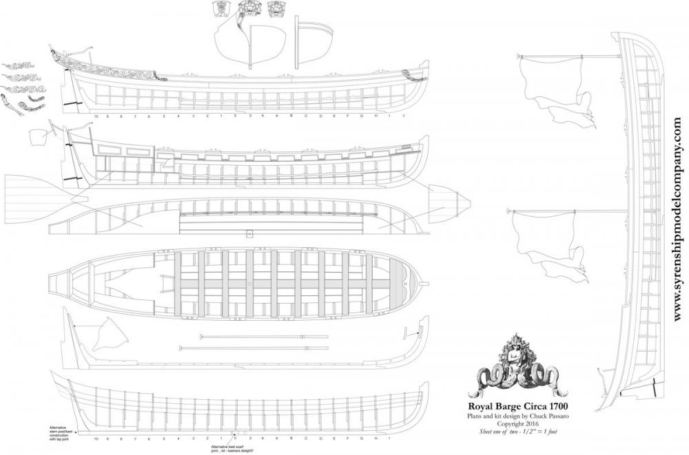
Just wanted to give all of you a more detailed look at what the new Queen Anne Style Royal Barge project will look like. You are looking at the preliminary draft for the plans. A PDF is below for a more detailed look. I am not worried about theft because there are no laser cut parts or templates shown on this sheet. I removed those. As the project and prototype gets built, more details will be added to aid the builder. Including those parts which were removed as theft prevention. This is why it is so important to have someone else build the project before its released. They will give me feedback on what additional views and parts would be helpful to include on the plan sheets. And when its completed they should be quite detailed....even though I think what is shown is probably already detailed enough for most folks. As you can see. This sheet includes many views of the model at various stages of its construction so those elements can be more easily seen. This includes a planking expansion on the bottom of the sheet. With the plans fully developed all that is left to do is build the prototypes....two of them. Make adjustments...Update and embellish the plans where needed...write the instructions.....and then start on packaging and production. This will include making all laser cut parts, cast decorations...and wood decorations. The model will be nearly 19" long and 3 1/2" wide at 1/2" scale. It will very closely resemble the contemporary model pictured. Let me know if you have any questions. Chuck queenannebargeplanmsw.pdf

- 269 replies
-
- 25
-
-
- Queen Anne Barge
- Syren Ship Model Company
- (and 1 more)
-
The sizes arent based on looks and instead based on factual data and tables....whatever you decide to go with its fine...but it will be much too large historically speaking. Again its just my opinion....but rather than just try three sizes of blocks and 4 sizes of rope for the tackles willy-nilly. It is best to refer to the historical tables and contemporary sources for rope sizes. Basically they used 6" blocks...give or take, depending on the size of the gun. And the appropriate sized rope for a 6" block which in my opinion is around 1" to maybe 1 1/4". I suppose you could maybe go as large as .018 rope for the tackles but its pushing it to the higher end of the spectrum.
- 843 replies
-
- 2
-
-
- niagara
- model shipways
- (and 2 more)
-
It looks OK but I will say that at that scale the rope you are using for the gun tackles is way, way too thick and out of scale. At this scale the blocks for the tackles would have been 6" long which translate to 3/32" blocks. The rope for the tackles would need to be .012 at the largest. Its just way too heavy. to have anything larger than that in my opinion. I would also go with .035 rope for the breech lines. But thats just my opinion for rigging those guns at 1:64 scale. Here is a photo of Cheerful guns at 1/4" scale using 1/8" blocks for the tackles and .012 rope. The breech line is .035. At 3/16" scale I wouldnt go much larger than that. Again its just an observation and my opinion. The best method to use .012 rope on the smaller blocks like 3/32" is to first stiffen the end of the rope with some white glue. Once it dries, cut the end of the rope on an angle to make it into a point like a needle. It should be stiff and sharp afterwards. It will slide through the holes in the 3/32" blocks just fine. Another alternative is to use a needle threader. No stiffening required. But I dont find that necessary as long as you can handle the small blocks in your fingers comfortably. Hope this helps. Chuck
- 843 replies
-
- 6
-
-
- niagara
- model shipways
- (and 2 more)
-
Thank You so much.....I will hopefully be back at it this weekend after I finish restocking blocks and rope. Chuck
- 1,051 replies
-
- 4
-
-
- cheerful
- Syren Ship Model Company
- (and 1 more)
-
I dont think so Antony....this is the 1700 version. That one was kind of easy to figure out. Unless I am not understanding what is wrong with the one posted. Can you elaborate? If I understand it correctly as a Yank.....before Ireland became part of the united Kingdom there were fewer bars in the flag and its the same top and bottom.
- 269 replies
-
- 9
-
-
- Queen Anne Barge
- Syren Ship Model Company
- (and 1 more)
-
Thank You...its so very confusing and contradicts other dates and standards. Maddening really. You think it would be very cut and dry what years these things were used. So many sources have different dates and different images for these. I am going with number 4.
- 269 replies
-
- 7
-
-
- Queen Anne Barge
- Syren Ship Model Company
- (and 1 more)
-
Thank you very much.....That is great information. I guess either one would work but since this will be billed as a Queen Anne Style Royal Barge I will go with that one. There will be a bust of Queen Anne on the transom. So its a perfect fit.
- 269 replies
-
- 6
-
-
- Queen Anne Barge
- Syren Ship Model Company
- (and 1 more)
-
Thank you very much guys....its tough to look at so many variations of these....its like playing...."one of these things is different than the others" when you were a little kid. As you can see this is not one of the choices I selected before....LOL. It will go at the bow with the union jack in the middle.
- 269 replies
-
- 6
-
-
- Queen Anne Barge
- Syren Ship Model Company
- (and 1 more)
-
But which one.....its so darn confusing and I thought there might be some English chaps that know for certain. Searching the web and researching in some books I have come across so many examples. I dont want to pick the wrong one or maybe they are all right...who knows. Lots of flags out there and its bloody confusing which one would be correct. What I am trying to prevent is after buying or making a few hundred of these for a kit, that an MSW member with the expertise needed tells me I used the wrong one. I am trying to avoid that and figured I would ask those with the knowledge up front. The English love their flags,,,they have a flag for almost everything and it changes all the time. There surely must be someone on this forum that has an in depth understanding of all this..."Fun with flags"
- 269 replies
-
- 4
-
-
- Queen Anne Barge
- Syren Ship Model Company
- (and 1 more)
-
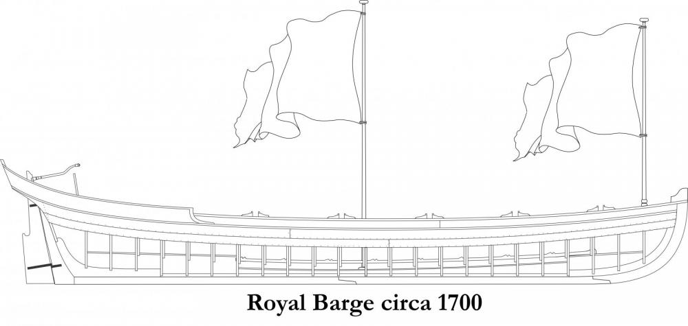
Thanks guys...But I need help with a flag suggestion. Both kits are seeing some progress. I am now trying to determine what flags to include. I know one will be the Union Jack but I m at a loss to what the other should be. She is a typical Royal Barge circa 1700. I would appreciate any feedback on the secons flag for suggestions. Chuck
- 269 replies
-
- 3
-
-
- Queen Anne Barge
- Syren Ship Model Company
- (and 1 more)
-
Some criteria for starting a new group project
Chuck replied to Chuck's topic in Group Projects on Model Ship World
I am working on creating a simple group/class for carving a very simple design. Stay tuned. I will be presenting it to my local club first to see how it goes and then I will present here. More details will follow shortly. This is a short term project I think many will enjoy.- 29 replies
-
- 13
-
-
As long as a topic about what we do as developers doesnt evolve into a sales pitch I am all for it should the membership be interested and have questions. I would also welcome the "big boys" as you call them to participate although I think that isnt the true picture. Many of these companies.......Admiralty Models, Caldercraft, Bluejacket, Maristella, Dusek, Seawatch Books included, are not the big boys. They are still very small by most business standards and are Mom and Pop type operations with sales NOT in the millions annually. Hardly considered big business like some older more established companies like Model Shipways, Amati, or Corel and others. Although I may be mistaken. The true definition...if you are in business with under 2 employees you are a micro business.....with up to 50 employees a small business etc. But to preserve this topic as a way to allow our members to communicate their wish lists and preferences for subject, price points and materials..... I still ask that no commercial folks post here. Having said that, if our membership wants a topic where they can ask our sponsors some kit development questions or respond to other inquiries and see a slice of what the development process looks like and costs....let me know by replying here and I will start one. I am just hesitant because I dont want it to be a big commercial or very sales oriented topic. Or for one or more such companies to monopolize the conversation. All of our operations are probably very different. Same is true probably for our business philosophy. It may be better for each dealer to just set up their own topic here..... There is really nothing preventing any vendor right now from starting a topic in the traders and dealers section right know detailing what it takes to start and finish a particular project. Sort of what Maristella has started here (topic) but he hasnt gone into costs and differnt things. Its his choice. I have already started one for Syren here....kind of...I would be more than happy to discuss any aspect of my development process and philosophy...as well as costs/challenges. I think the topic already contains such questions from our members. I am not adverse to talking about it in more detail either...just pose the question in my topic. So I guess what I am saying Dave....is that it may be better to just create a stand-alone topic for the Lumberyard rather than have a mish-mash of commercial gobly-gook in one large topic. Just my two cents. So feel free to start your own. Currently I have found this topic fascinating....for my area of expertise..(not sail to steam, not POF) Preference for complete kits of frigates and ships 1750-1840ish as described by many....POB ..1/48 scale or 1/64....with better materials.....huge detailed instructions with crisp Hi res photos in color....high end fittings and not the usual crap...better rope and blocks....all for what has been averaged out to around $200-$500. Dont make a ship already available as a kit......plenty of particular ships mentioned so thats not an issue. That is a tall order. There are a few willing to pay more but most are not....we are talking years to develop each project and thousands invested in that development. I probably should have opened up a pizza parlor instead. I would not have gained that info had this topic been over run by input from the developers. The same is true if the topic was watered down by having a similar topic competing with it, because some developers are chomping at the bit to get into the conversation. So yes, Dave, feel free to start a stand alone Lumberyard topic. As the info I am getting must continue to be collected un- abridged. It is just too valuable to muck-up. For me anyway. And feel free to also comment in my topic as I will feel free to comment in the Lumberyards. I think it will give everyone a lot of insight into our individual operations. And we developers will have a lot to gain from talking to each other in our various individual topics. I am sure we can all help each other move the hobby forward by letting folks know about our challenges commercially. Again, I am sorry for going off track here a bit.
- 117 replies
-
- 13
-
-
Some criteria for starting a new group project
Chuck replied to Chuck's topic in Group Projects on Model Ship World
A group on an intro to carving would be great......that subject might be a little advanced and intimidating...but maybe say this. As it is applicable to the carved work in bas relief that is common on many period ship transoms and trail boards.
- 29 replies
-
- 15
-
-
Some criteria for starting a new group project
Chuck replied to Chuck's topic in Group Projects on Model Ship World
Well right now I am just trying to muster up enough interest in any subject. Doesnt seem to be going well. Plus Dave and others are missing the point with the fitting group projects. It doesnt matter that there are instances where a capstan is made in a build log. There is no duplication....... The idea is that a group of folks may want to try and build a typical capstan correctly and choose the same subject plan/or primary source. Then build it TOGETHER while sharing ideas for how best to accomplish the task. For example...see the wonderful model below. With your line of thinking ....which I think is flawed, one can say that there are currently so many Hahn scratch build logs underway that there is no good reason to start a group for one. It would be a duplication of effort and redundant. There has been so much written about his method....and tried before, that it would not be worthy of a group. But ......because you folks missed the whole point about ..."group" and "together" "building the same subject" "from the same plans together" .....I think a Hahn group would be a good idea and so would any project as a group who wanted to try and build any subject as a study and exercise in technique or for any other reason. This includes any current kit on the market. It doesnt have to be a special project designed new...or by a commercial entity specifically for the purpose of using it in a group..... It can be a group build entirely from scratch.....buy a copy of any plan available....OR you can collectively choose to start a group building teh M.Shipways kit for the Armed Virginia Sloop....It doesnt matter how over done it is...as long as members of the group will get something out of it....learn together and progress there hobby adventure. A group of brand new model builders getting together to build a simple kit as a group will absolutely be of benefit to them in the long run. It is easier to "learn" as group than on your own....sometimes....and for specific people who prefer additional input and support. A group project for making sails is an EXCELLENT idea....a plan of any sail can found easily enough....that same plan can be used by many folks to make a sail....imagine, some trying different materials.....others trying different techniques. All to produce the same sail. It would be so valuable to have that data in one place for everyone after the group has completed. Excellent suggestion. But someone has to take the lead and get it organized.....find that plan and find 6-8 people ready to get started. That would be an invaluable resource to have for everyone. AND it wont be a project that takes years to complete....and you can participate while still working on any current projects. Frank gets it.....that is whole point of a group learning experience. -
The topic is getting too general.....remember what is of most help to us developers/publishers/magazine editors trying to decide what you guys want as a subject to build or learn about. As a group we are interested in subject matter choices. I think we all know you would like better instructions and better wood and better everything. No need to repeat that stuff. Its been a given for decades. Specifics if possible or types and periods....I am not trying to intervene....just moderate a little. The generalities are not very helpful to be honest. You guys say that other stuff all over this forum. Think of it in terms of subject matter. So far the most often mentioned subject is sail to steam.....larger scales and detailed ........around 200 to 300 dollars. With that info and knowing more than just a few want one...you actually stand a chance of getting it. Maybe more articles on that period in the Research Journal too....all because we had a lot of folks tell us they are interested in it. Just mentioning you want better pictures isnt going to get you that model or article or new Seawatch book. Again just playing the moderator here. If we had 20 guys say they were interested in a certain ship or period that hasnt been done before, you better believe that all of the above companies would want to sell you something about it. - Name of ship .....or type - Country of origin - date - Material choices and what style...POB or POF or Solid hull ETC - Price range you would expect to pay...whether realistic or not -How long do you prefer a build to last from a kit. Will you want to spend 6 months for a small kit or 6 years for that 100 gun French frigate from 1820? -Advanced or beginner......something in-between?
-
I think thats a discussion for another topic because it would literally take over this topic....my guess its a little of this and a little of that....remember we are just model builders too. So we build what we like. But I would suggest that you start a new topic on that if you are interested in having all of us kit developers chime in. Plus, yes, its just a hunch based on info from topics like this one and whatever feedback is out there. Which is why I thought we would start this topic. I would hate to muddy up this important data with another subject.
-
Not that I am getting involved with the topic of kit subject matter but I do feel compelled to respond to this as it was a direct request of sorts...so please excuse the interruption. HSM wrote Oh, one more thing that I would like to see (from Syren specifically) is an option for bulk-orders of blocks. If you could offer a package of blocks to replace all of the kit blocks in the MS Rattlesnake (for example) builders could order that for the MS kit or any similar ship. It is impossible to offer such a package for every kit, but a few generic 20 gun, 50 gun, 100 gun packages at 2 or 3 different scales could be doable... It's amazing how easy something is to suggest when SOMEONE ELSE has to do the actual work ;-) Sadly, this will never happen but please allow me to explain why. The answer is three fold. Just so everyone knows. - First...I would need to double if not triple my output of block/rope production so I could stock enough of these packages for individual kits or ship types. - Second...the amount of time needed to just package up these blocks and rope now is enormous. So to package by hand different amounts of different sizes included labeled packages and then sort them would take hiring another person to do that almost full time. And when they were done....they could sit on the shelf for months or even years before someone might be willing to buy such an upgrade package so specific. -Third...It would take weeks...months or even years to research so many specific ships....research that really should be done by the builder. Especially if I have never built the ship before. This is a question I get all the time....I got this one just a few days ago. I think some folks just want the work all done and spoon fed like it was a fast food restaurant. "I am building the Vasa and would like to replace all of the blocks and rope in the kit with yours. Can you tell me how many blocks and what sizes I would need? I also need to know how much rope to buy. The kit isn't very good in this regard so sizes and quantities are unknown to me. Is there some hard and fast rules that would tell me what sizes to use in the different areas of the rig? Any help would be appreciated. I have just finished the hull and I am anxious to get started on the rigging as quickly as possible. Do have expedited shipping?" I could spend several months writing what would amount to be a treatise on this subject for this customer.....while gathering the quantities and lengths....but seriously...who is building this model. There are usually many books readily available to help the model builder figure all of this stuff out....as much as I want to be everyone's shortcut and help them out....it is an impossible task. So please dont get mad if I respond in the usual manner if you should ask this question... I never built it...but there are several books on the subject. Please refer to the parts list in your kit as a starting point. Everything is in stock and ready when you gather up all the information. You may consider signing up on Model Ship World to ask those questions. I am sure you will find many people who have built that kit. Many ask for this because they also believe as a bulk package it will be cheaper. But in reality because of the work involved as mentioned....I would have to charge a whole lot more. Its cheaper if you guys do the math up front. A lot less work for me too!!! Oh and if I can slip this in....Wasp is on my short list already.
- 117 replies
-
- 20
-
-
Kurt, Dont be shy....my guess is you want a nice shiny new tugboat kit? Again I am just guessing. Please everyone.....just dont say its a great topic and you will be listening...or hit the like button....please lay it all out there. The more that start to participate here, the more people will feel less shy about posting. Dont be shy. Who will get the conversation started?
-
I thought I would start this topic because as a model builder I know what I would like to see developed into a kit. I am sure all of you have a short list. On the flip side!!! As a developer of commercial kits and projects, I have no idea what-so-ever what other kit builders would like to see developed. I am quite certain that this is true for the other kit developers. Its just a leap of faith based on so many factors. Including many who are respected sponsors of this site. Both old and large companies or the newer, smaller Mom and Pop type operations. We just dont know. Its a big chance to take without a direct line of communication. Bringing a new project to market is a serious investment in $$ and time.....our worst fears....nobody wants to build it or buy it when its launched. So please....I urge you all to participate. It would be a huge ....huge help. No more Victories or Constitutions...its the last thing the hobby needs right???? Maybe not??? Please tell us. BUT I would kindly ask that all MFG's including myself...and our sponsors...not participate in this discussion other than to say that you are watching and listening or if asked a direct question that warrants a response. I know you will be listening, just as I am eager to hear from our customers. This will alleviate any fear that we may be trying to steer the choices or monopolize the voice of all of you kit builders out there. SO...please do feel free to share your own short lists. Or even just one. Consider this your direct line to the kit developers out there.....I know I am listening. The others would be at a loss if they dont. Otherwise, we will just keep developing the same old stuff and hopefully one of them is what you want. BUT here is what we need to know...or at least me as a developer. - Name of ship .....or type - Country of origin - date - Material choices and what style...POB or POF or Solid hull ETC - Price range you would expect to pay...whether realistic or not -How long do you prefer a build to last from a kit. Will you want to spend 6 months for a small kit or 6 years for that 100 gun French frigate from 1820? -Advanced or beginner......something in-between? You get the picture....It would be interesting to see if we have any HMS Thunderer (74 gun) at 1/4" scale in POF built from Boxwood for under $200....If we hear a lot of that, then its probably time for me to look for a new job...LOL. I learned as a young boy that if I didnt tell my parents what to get me for Christmas....I would end up with a lot of socks and underwear....LOL and I will thank you on behalf of all of our fellow kit developers and MFGs. This will make it so much easier for our businesses to grow and the hobby itself to grow. Chuck
- 117 replies
-
- 20
-
-
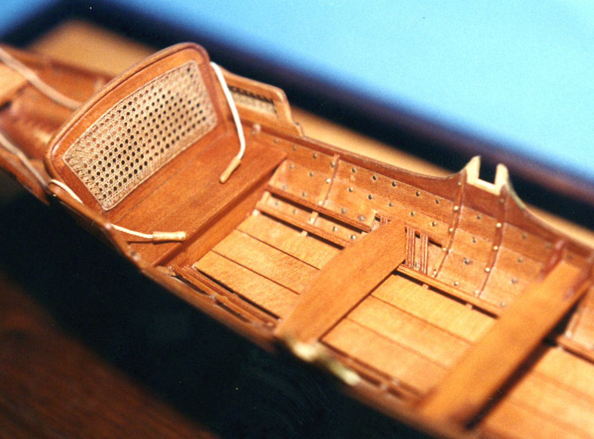
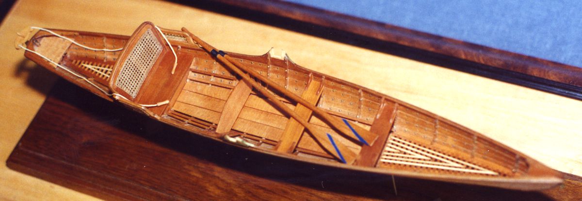
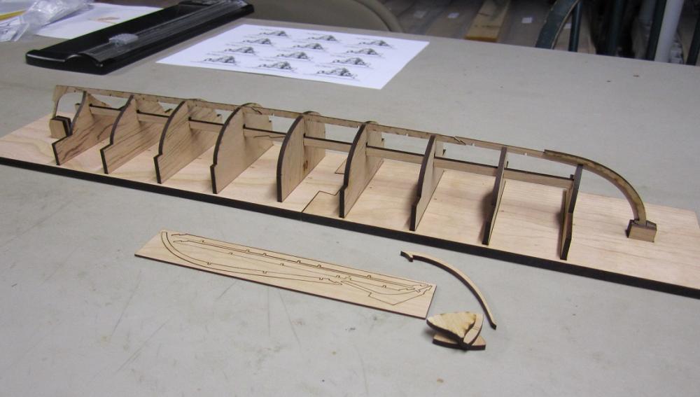
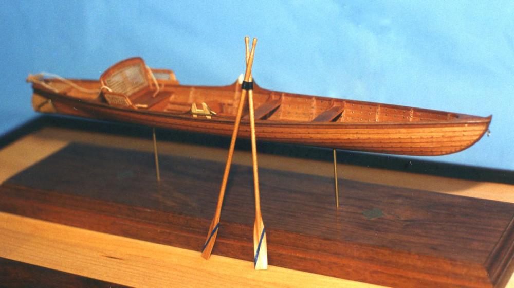
No, that is project number two.....both are currently underway.....the Syren Factory is at full capacity!!!! That is being worked on by Dan Pariser and will take this philosophy to the next level..... You will lapstrake plank the entire hull for a Thames river skiff..1880...all planks are laser cut and pre-spiled....with etched reference lines and instruction. You get the plug...actually laser cut parts....then you plank it like you would with a plug and remove the shell..then insert the frames inside afterwards. Then there are all the little details. So that project takes the learning experience even further. Both are being worked on right now. Its different than the barge as that kit has removable centers that become the frames...a slightly different concept. But its all to teach a differnt method of clinker planking with hopefully very thorough instructions and lessons for doing it. The model shown is Dan's and it is also made from Cherry and boxwood. They actually make the real things out of cherry and still use these skiffs today. Dan will be starting a build log of this model as well once it gets further along.


- 269 replies
-
- 27
-
-
- Queen Anne Barge
- Syren Ship Model Company
- (and 1 more)
-
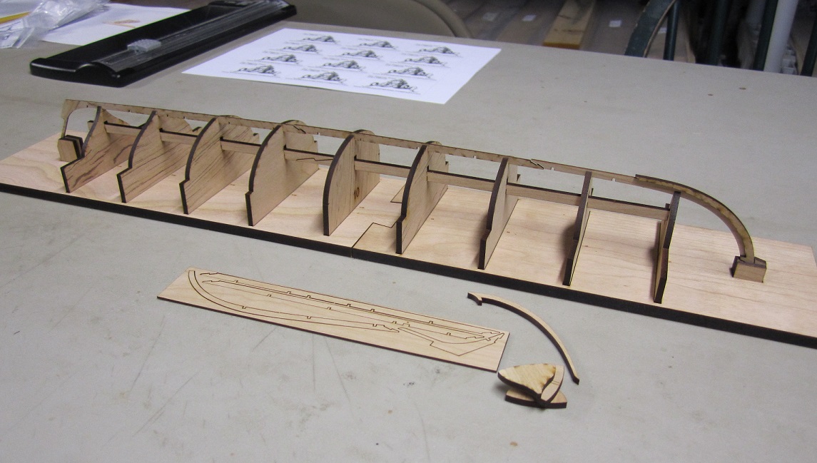
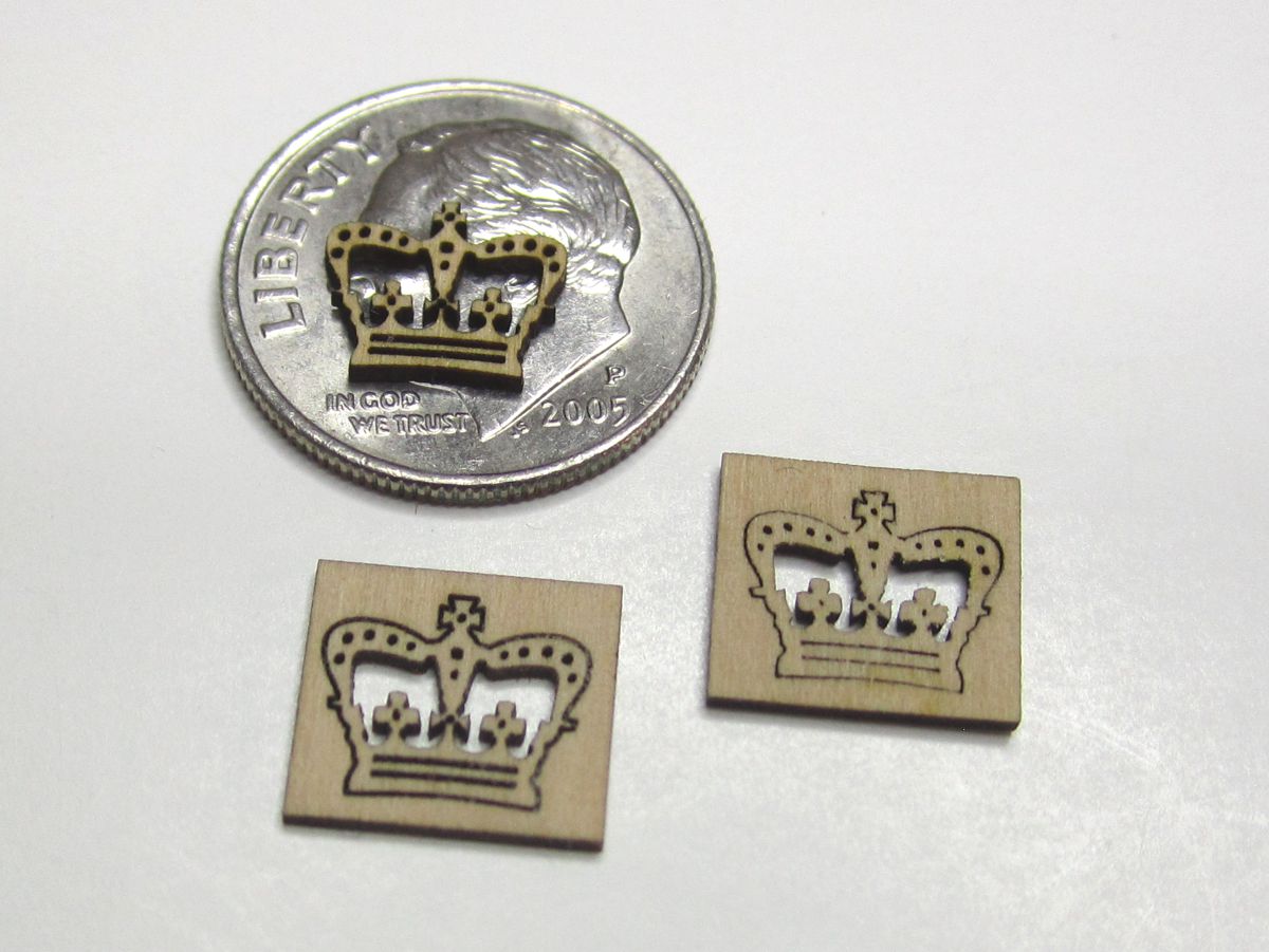
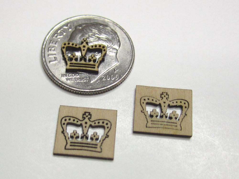
Mike I understand what you are saying....but rest assured ... this is most certainly an advanced kit. Although the parts are all laser cut and the jigs and design concept will alleviate much trouble....the builder will need to proceed very slowly and with much care. To explain a bit about my philosophy for kits. - My goal is to design kits that wont look like kits when they are built. The quality of the wood and the parts and the historical accuracy. No ply for fittings...no metal castings....no skimping on the final visual product. To design them in such a way that folks can build them with the same few tools they would use to build any other kit straight of of the box. Yet when its done, and placed right beside a scratch version of the same subject...most wouldnt be able to tell the difference. The design I hope will inspire others to use the same concepts after finishing it to slowly cross over to scratch building. Or adapt the concepts for other kits that are lacking. - For example...first I wanted to introduce a model that would serve as an introduction to clinker planking. Not the whole hull...but just a few planks. So builders might not be nervous about it. It will literally be a step by step intro lesson on clinker planking...how to bevel...what to bevel etc. See below for the one plank - second...this model will also serve as an intro to carving. Yes there will be three small resin castings, but the majority of the carved scroll work you see on the sides of the hull and transom will be carved by the builder. These arent complex figureheads or difficult subjects to scare folks who never tried it. Or never used boxwood. You will get the piece laser cut from boxwood flat and ordinary... and you will learn some simple techniques to get started carving...with a few extra pieces just in case of a mishap. How to secure the piece for carving, how to use a stop cut, how to shave and carve with simple tools....how to undercut areas etc. Step by step. Nothing to fancy and elaborate...no expensive tools...just giving it a try with a little help. At least the way I have always done it...I am sure that others will have a better way but this will show how I do it. These are the two main features that are the focus for me on this project as well as creating a way to frame the boat properly with floors and futtocks like the contemporary model. And NO...the carvings wont be that small. It fits on a dime because I was just testing my laser cutter to see how hard I could push it....how small can laser cut something intricate and still capture some detail. That is pretty dang small. The real thing is about six times larger. - So for me...designing this kit was a way to introduce a few things that are lacking with most kits....mainly they all look like kits unless you do some serious bashing with no guidance to go with it. Why not start out with great materials....and guide the builders through it as if it was stepping stone to scratch building. Having said that... The jigs and laser cut parts I provide are something I would normally make for myself if I were building this from scratch...by giving them to a builder who might not have the tools or experience to create them, they will at least get a chance to see a pre-spiled plank so they can understand and can visualize why using a straight strip isnt going to work. They will see the spiled shape and think....this is nuts.....then after they place it on the hull without any difficulty, hopefully a light bulb will go off. Then MAYBE they can apply what they have learned and experienced with this kit on the many other kits they build...or scratch projects. Its hard to explain but I hope it makes sense. It wont be a beginner kit. It will be an advanced kit FOR intermediate builders looking to try something they havent done before. Now I keep showing the same image of the same contemporary model. It wont look exactly like this one...but its close. It will actually look a lot more like the one pictured below except for the transom carving. I am referring to the colors and the lack of carving inside....just bare panels. This is remember just an intro to carving. Note how the planks are fastened....not treenailed....they are nailed. Nailed to the plank beneath it. Just something new to learn and I am learning right along with it. And yes it will be a challenge. Chuck

- 269 replies
-
- 31
-
-
- Queen Anne Barge
- Syren Ship Model Company
- (and 1 more)