
Chuck
-
Posts
9,088 -
Joined
-
Last visited
Content Type
Profiles
Forums
Gallery
Events
Posts posted by Chuck
-
-
Roger!!!! So great to hear from you . I was actually trying to reach you so I could welcome you back. So happy you are posting some log images of your Syren. Wonderful news.
Chuck
-
Just use the upload feature here. It works a treat and its free.
Chuck
-
The second is no different than the first. I recommend lining off your hull as mentioned in several of the online articles here. Then shaping and spiling your planks to suit. That is truly the only way to do it properly. I would also add that using only the kit supplied planks might be a problem as you may have to cut your shaped planks from wider sheets of wood.
Chuck
- fnkershner, WackoWolf and mtaylor
-
 3
3
-
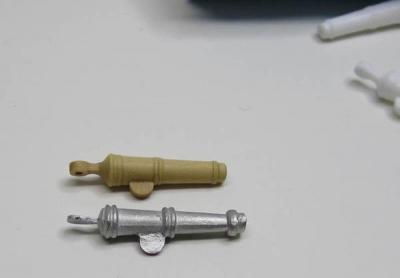
Thats good news... here are some pics of the original and cast versions I sent them. And one all painted up. For replacements, just call them on teh phone and they will send you a new set for free. Dont use those crappy ones. I have no idea where they got them and they are the wrong size and wont fit.

Chuck
-
...all books are sold through the Seawatch site from the US.
Chuck
-
You can still buy that book new...its $78 Euros. So used...depending on condition, about half the price. As far as your models....unless we had a list of what they are we couldnt say.
Chuck
-
Looks really good so far. Glad to see another Syren being built.

Chuck
- kjpeters and makoa20120
-
2
-
-
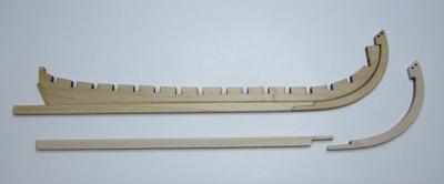
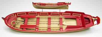
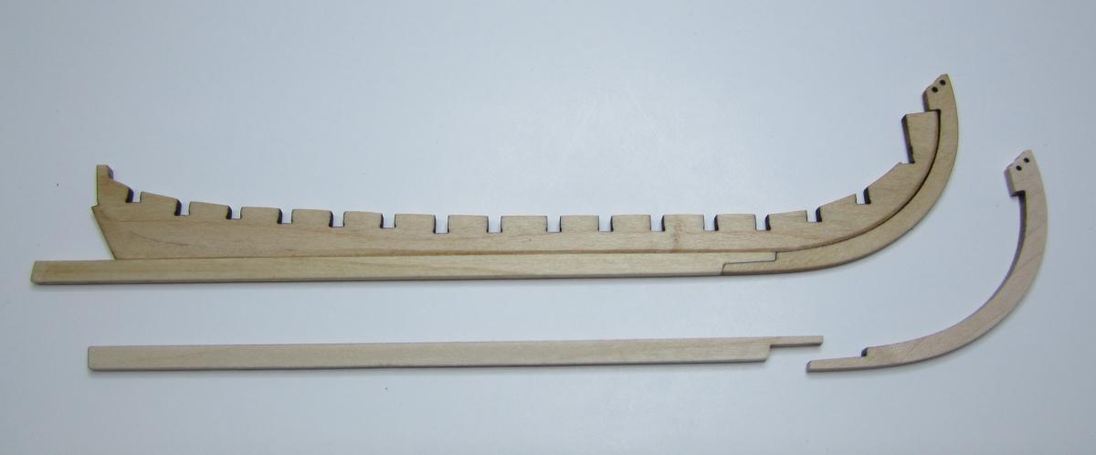
To start...the slotted false keel was tapered from the bearding line to the outside edge. This created a simulated rabbet once the two keel pieces were cut to shape and glued into position.
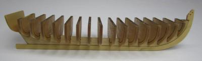
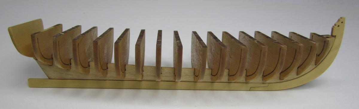
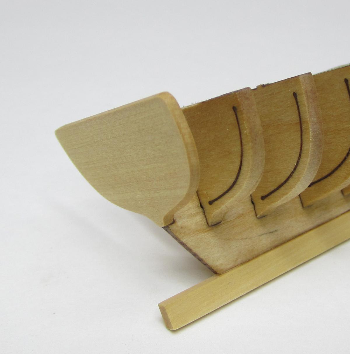
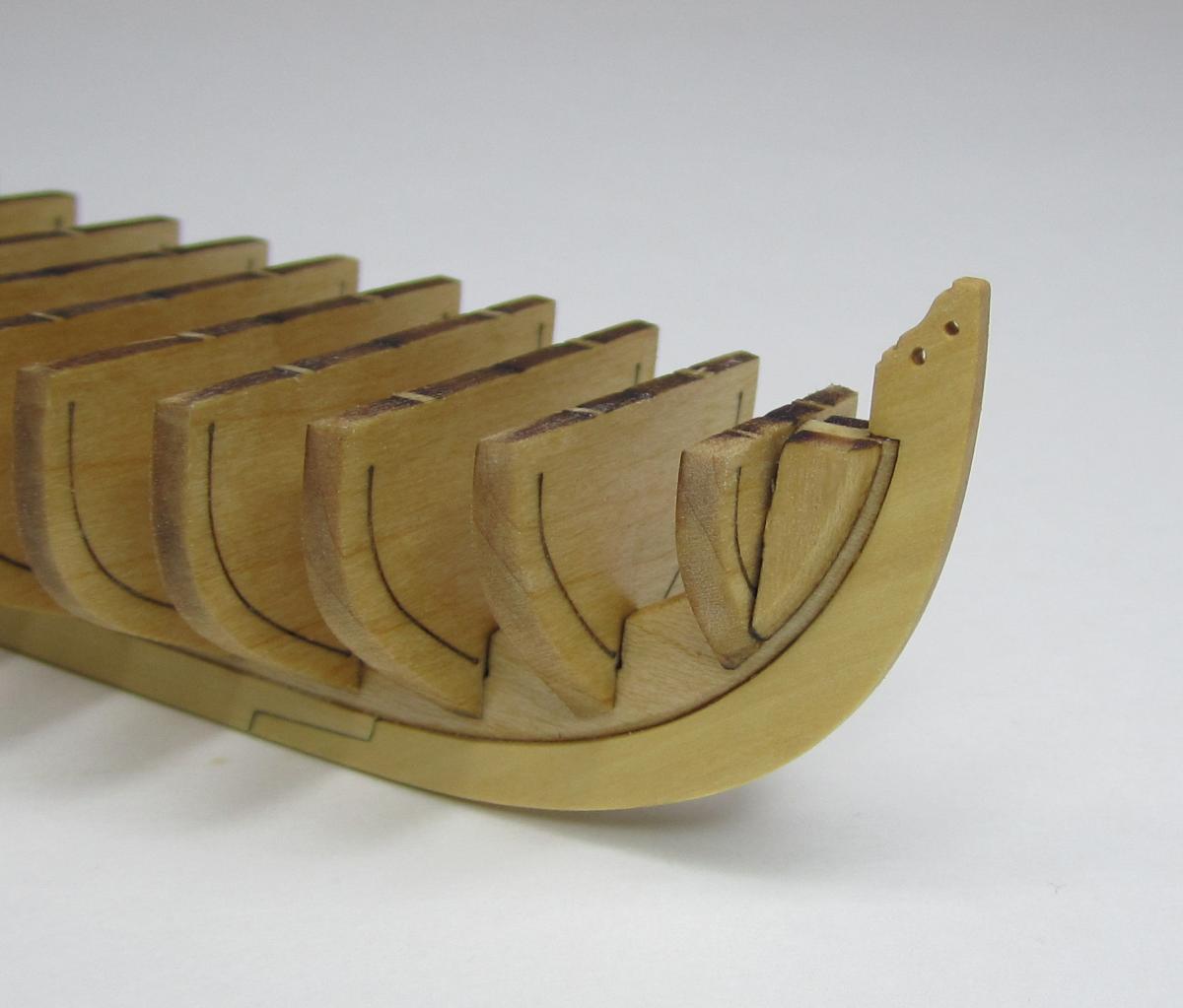
Then the 16 bulkhead frames were added. I had these laser cut to save time. They were designed in a way that the center sections are removable. They are held to the frames by small tabs. Once the hull is planks I will file through the tabs and snap out the center sections. Care must be taken to square up the bulkheads with the keel and ensure they are straight so the the proper hull shape can be obtained. You could further stabilize the bulkheads by gluing a temporary batten across the tops of them which will be removed before I start filing the center sections free. But I am not a heavy handed builder so I just started fairing the hull immediately. I use d alight touch while beveling the outside edges of he bulkheads. The transom and bow fillers were added just prior to the start of planking.


-
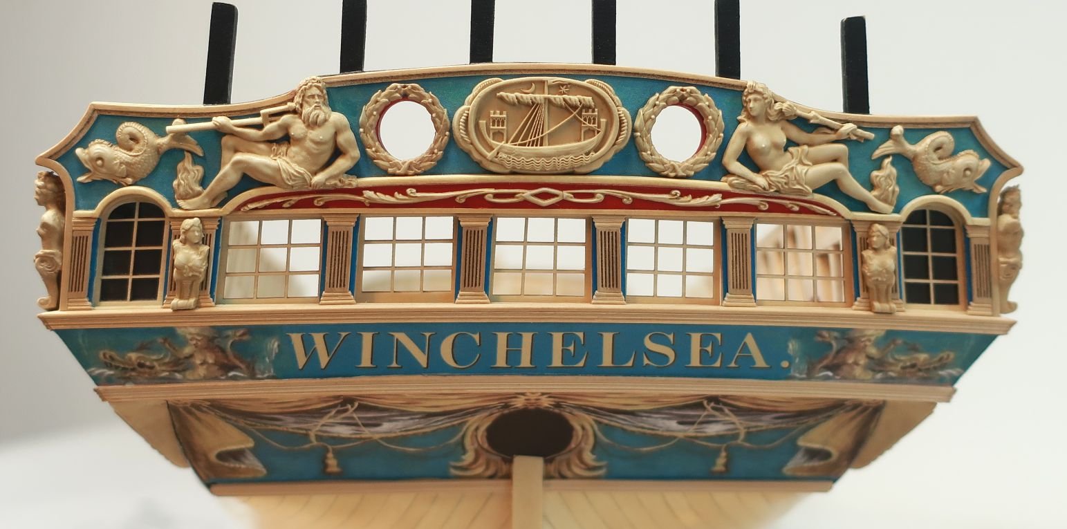
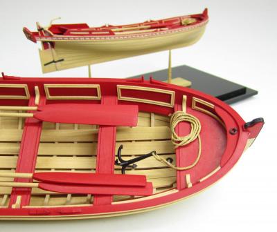
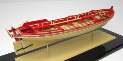
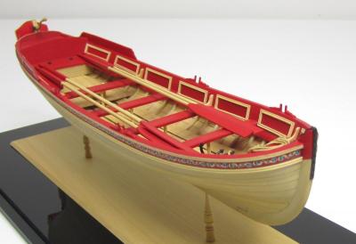
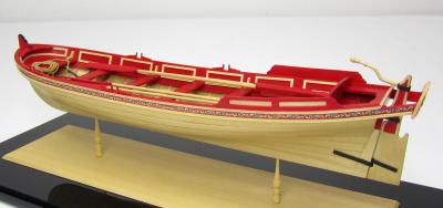
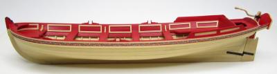
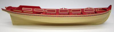
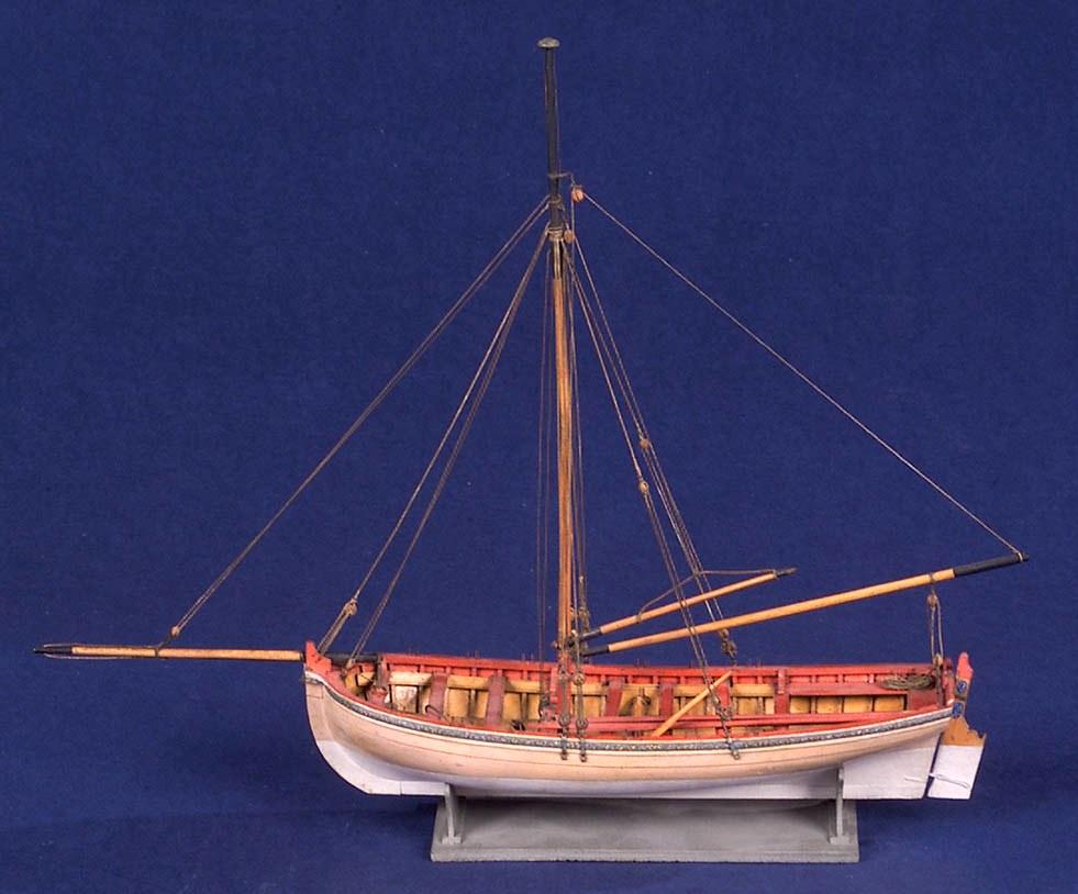
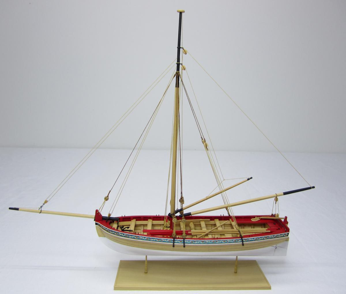
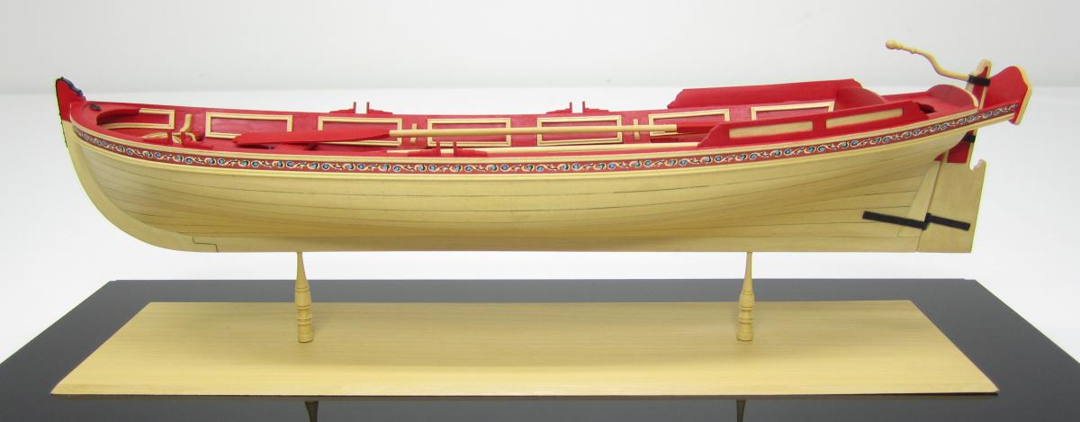
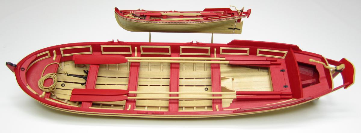
This 26 foot long was designed based on a contemporary model in the National Maritime Museum shown below. This longboat was used circa 1750-1760 and was typical of this type of small craft. Plans for this model and MS kit prototype were drafted based on the contemporary drafts from the period. The longboat has been decorated to match the NMM model that inspired it. Even though this model was inspired by another, many other color schemes are possible.

There are many more contemporary models that show various decorative themes. Another very good
source of information on these small boats is “The Arming and Fitting of English Ships of War” by Brian Lavery. This book discusses the many details you sometimes find on these Longboats.
Another good reference is "The Boats of Men of War" by W.E. May.
Some references to these book will be mentioned throughout this project.This scratch project was the prototype for the Model Shipways kit. An image of the finished model is posted below and can be compared to the contemporary model above. I Also below you will find the PDF instructions for the kit which has more details.

- maddog33, Jack Panzeca, Nikiforos and 2 others
-
5
-
Check here.....the question was asked already...
http://modelshipworld.com/index.php?/topic/279-size-of-photos/
Please read through all of the topic titles in this forum first before you post the question again.
Thanks
-
-
Can you give us the info and links where you had the stencils made???
Chuck
-
Rusty...Its like seeing an old friend again....I am so glad to see it here.
Chuck
-
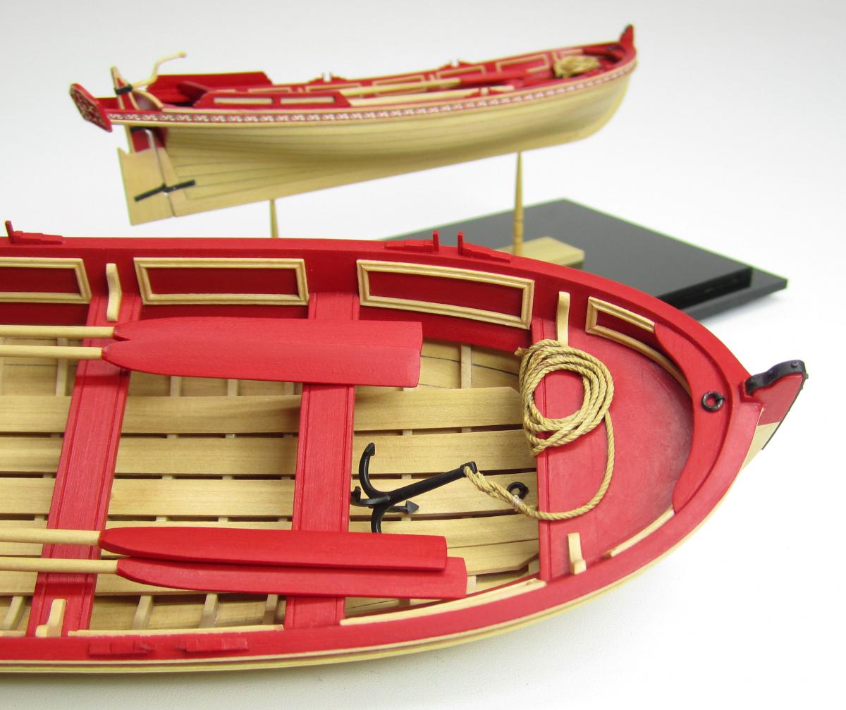
Now I only had to add a few small details to finish it up. This was a relatively short project but was a lot of fun to build.
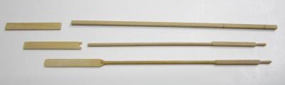
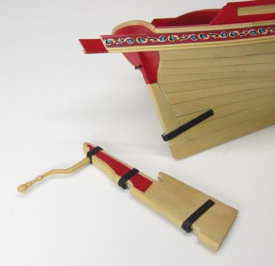
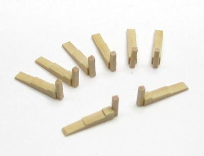
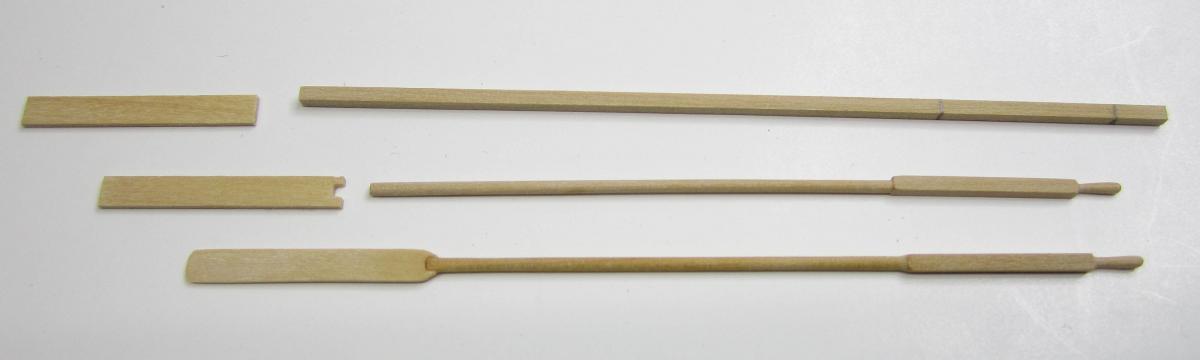
I created the oars in two pieces. The handles were shaped on my dremel which I used as a poor man's lathe. Once it was chocked up....I sanded and filed the square strip until it was rounded to spec. But I left the square section untouched to create the final look which was common for the period.
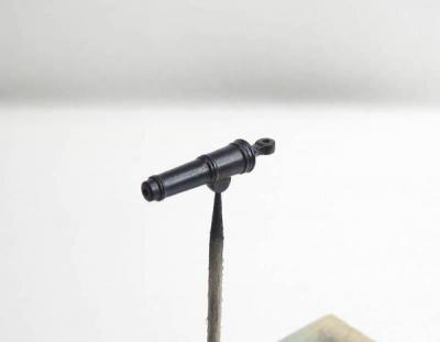
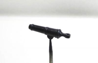
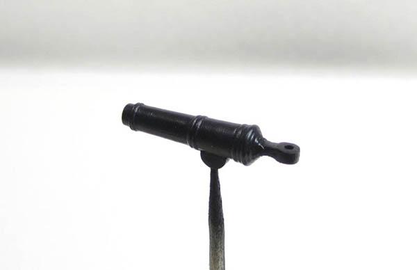
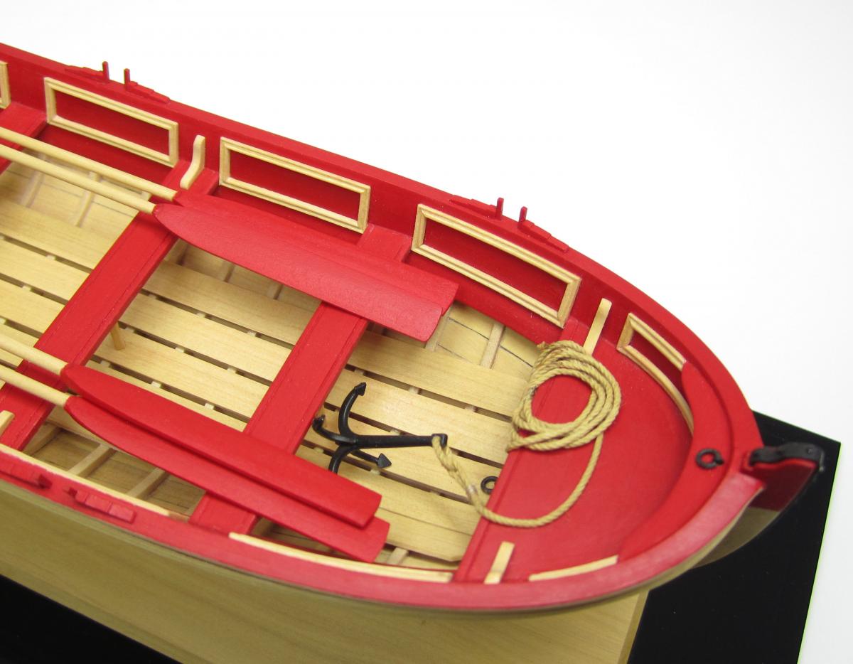
The grapnel was a casting from Model Expo. Seeing as this was a prototype for a future kit, I was asked to use one that they already had in stock. It was a nice fitting and was perfectly scaled.
That finished off the project. I turned the display pedestals with my Dremel because they were small enough to chock. They arent a perfect mating pair but look OK to my eye.
Thanks for looking and as always, comments and questions are appreciated.
Chuck


- GrandpaPhil, Mirabell61, j21896 and 3 others
-
6
-
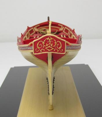
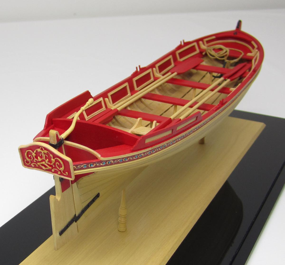
Next up was the rudder. It was straight forward to cut it out of a sheet of boxwood. Then it was tapered so it would narrow aft, and the fore side was shaped and slotted for the pintles and gudgeons.
I used styrene once again for the pintles and gudgeons. Its easy to bend although you must do it slowly so it doesnt break. If you go slowly it gives the plastic a chance to bend rather than fracture. It drills remarkably well. The bolts heads were simulated as I mentioned earlier.
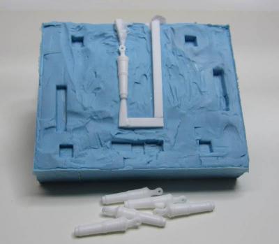
The tiller was shaped by hand. I patiently filed and carved it from a larger piece of boxwood. Once the rudder was placed in position, I could glue the the decorative transom in place as well. I created it by sculpting the details on a thin sheet of wood with Sculpey. The wood blank was 1/32" thick and cut to the shape of the transom. I added the sculpted details a little at a time and baked it in my toaster oven to cure it.
Once it was completed I made a mold and casted a one piece resin copy which is what I used on the model.
Chuck
-
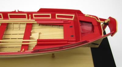
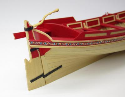
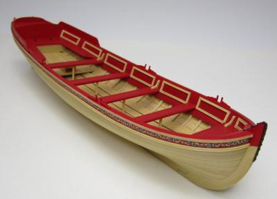
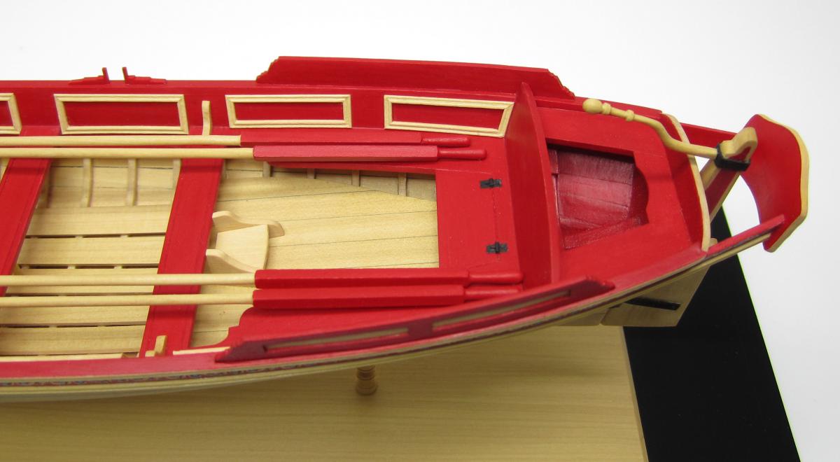
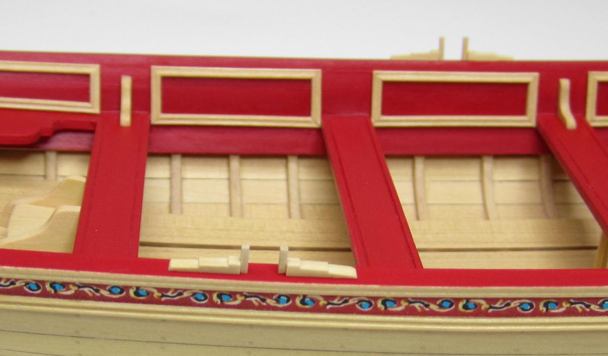
I built the four oarlocks next. They were made with two pieces as seen below. They were glued on top of the cap rail and then painted.

To finish off the details on top of the cap rail, I constructed the paneled splash boards by the cockpit. Each splashboard was mad using two layers of 1/32" thick boxwood. One was solid and the outboard one was cut out to create the panels. Once glued together they did a good job of simulating panels. They had to wet down and bent with heat from an old hair dryer. They were bent to conform to the curve of the cap rail. Finally...they were carefully painted as I tried to leave the center panels natural.
Chuck
- Mirabell61, avsjerome2003, Archi and 1 other
-
4
-
Looking great. Nice job on the plating...that came out particularly well!!
Chuck
-
What a beauty....I am so glad you posted the log again!! Thank you sir
Chuck
- ModelExpoOnline and Nirvana
-
2
-
Thanks Guys
Ryland...yes they do...the photos show a lot of detail and every little paint smear and mistake...LOL
I am using many pictures because my local New Jersey club will building this model as their next community project. We have fifteen signed up to build it. Its going to start in a few months. I guess I will be building a third Pinnace model very soon.

Chuck
- Mirabell61 and Archi
-
2
-
Yupp....But wait until you have the inboard planking on....I would aalso use that second layer of the sheer strake to adjust the height of the shear if need be to match the other side...If your starboard is a little low....then add the shear strake a little higher to compensate. Then put the cap rail on top of that after you sand teh extensions down later. But I am only talking about a slight correct if need be. You see how the bort side dips a bit where those extensions are higher?? The frontal bow shot shows that.
Chuck
-
Looks very nice...The planks look properly done in relation to the bulkhead extension tops. Do your best to make sure that they are consistent from port to starboard. Especially at the stern. The bow look fine.
Chuck
-
-


18th century English Longboat by Chuck - FINISHED - c.1760
in - Kit build logs for subjects built from 1751 - 1800
Posted
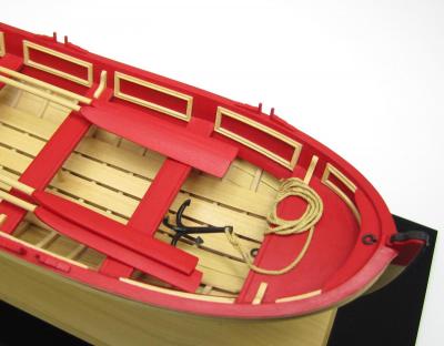
To start the planking, I added two strips on each side along the sheer. This stabilized the hull. It was pretty amazing how sturdy the whole thing got. Then I just continued down the hull with a few more. Then I switched directions and started adding them from the keel upwards. I met somewhere in the middle to finish the hull.
The strips were pre-bent to fit the hull both edge-wise and to conform to the bow and stern shape. When it was all done, I added teh stern post. Then it was time to treenail. I treenailed the hull using some Elmers wood filler. To help keep the treenails lined up I used some tape. I ran the tape down the hull being careful to line up one edge on the center of a frame. This was a challenge but I could hold the hull up close to teh light and see through the planking. Then I marked the locations of all of the frames based on the shadows that shown through the planking. I drilled some tiny holes (#78 drill bit) and then filled them. After sanding the hull I applied some wipe on poly