


Chuck
-
Posts
9,662 -
Joined
-
Last visited
Content Type
Profiles
Forums
Gallery
Events
Posts posted by Chuck
-
-
Thanks Greg. Yes I do fray the ends of the thread after I open the lay of the rope. Then I cut the frayed ends to the length I like and do the faux splice.
yes indeed the the splice is forever.
- dvm27, Canute and Ryland Craze
-
 3
3
-
After…your completed length of rope. I edited the post. Also look or search for a topic titled Using Gutterman polyester mara thread for making rope. You will find recipes and instructions and experiences from other members there.
- druxey, Ryland Craze and vvvjames
-
2
-
 1
1
-
If you are using polyester rope it will always unravel unless you cook it in a toaster oven.
not too hot…250 degrees maybe 275 for 4 or 5 minutes.
Just tie a simple knot on each end when you cut it free from the rope walk and then wrap it around an empty tuna can. But wrap the tuna can with foil before you cook it. Some cans can stain the rope when cooked. No issues with a foil cover however.
- Ryland Craze, druxey and vvvjames
-
3
-
-
54 minutes ago, palmerit said:
Do you just keep a bowl of acetone and a rag nearby?
Not really no....but that is a good practice. BUT I just use my finger to wipe away the excess. Keep in mind that I must stress that I use such small amounts....less than a drop really. There is never enough to use acetone on. I am talking about rigging of course. If you have a need to use acetone then my guess is you are using way too much CA. I mean just the tiny tip of a tooth pick is barely dipped into a few drops of CA squeezed out onto a scrap piece of wood. The tip of the toothpick is literally just a little wet with CA. Thats it. You dont need a lot of holding power as the ropes are not under extreme stress at all...that is unless you are one of those folks who tighten their rigging up like a drum, that it is so taught and with a lot of tension. There is just no need to do that and it isnt really good for you model. You shouldnt put your models under any stress because of rigging lines.
Just tight enough that the ropes are about to sag on the verge of sagging...and the best possible result would be to leave a little sag in some lines because that looks so much more natural and life like.
This is literally how much I use …and place it on a knot or faux splice. Excuse my 2 year old glue blob palette ..I just used my I - phone to take this video so I dont know if you guys can see it or play it. Maybe you can if you use your phone to look at it.
-
that is the stuff...should work fine. its about the technique...use a very small amount...rubb it off with your fingers to avoid shiny dark stain immediately. Just practice. But one package of sing and double blocks and some poly rope and spend a half day just practicing stropping using different techniques until you get better at it. Whether its a faux splice or like the way I prefer as shown in my titorial. Or even other methods. But it really just takes practice and persistance.
Chuck
-
What kind (brand) of medium CA do you use for this?
I use whatever is on sale...I have three different brands but all are medium CA.
And what do you use as an applicator? Something like a pin?
Just a round toothpick...
-
For rigging with polyester ropes you do have another alternative. I havent tried this myself but I have seen guys use this in my local club with great success. I may give it a try when I have to rig my Speedwell. But folks have used either of these with great success.
Gorilla Glue for fabrics including Polyester and Aleenes fabric glue
And
- RossR, Ryland Craze and JpR62
-
3
-
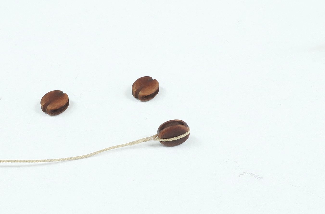
Here is a faux splice like Greg mentioned using medium CA....Not clunky and not shiny or stained. It takes about 40 seconds if you prefer using a faux splice like this.
This is Syren rope and blocks which is poly. Its really really about practice....and yes your fingers will get a bunch of CA on them but only a tiny drop is needed. Its just a matter of what you are more comfortable using. I will never say one glue is better than another. For me it is absolutely true that I prefer medium CA. But I have seen Greg use White glue in a way I could never. I could not achieve this same splice using white glue...I would need much more practice and yes cotton or linen rope instead.
-
22 hours ago, dvm27 said:
Faux splices can appear a bit clunky with CA. Faux PVA splices,
I agree with everything Greg has said. Its really just a choice. But I do disagree about splices looking Clunky with CA. They can and should look exactly the same...it just takes practice. If you are more comfortable and used to using one glue over another, then of course one will look better than the other. But this is only because you are not as accustomed to using one over the other....hence the practice needed.
I am partial to medium CA as the really thin stuff can be absorbed too much and spread as shown in the photos above on the wood. Those photos also show way too much glue being used and its just not needed. Just a little is needed and zero seepage occurs. I also use the medium CA on rigging all the time although very little. Very very little as you saw in my tutorial on stropping blocks. Its all about practice and choosing the correct density of CA.
Chuck
- Ryland Craze and JpR62
-
2
-
This project is now free…just click on the group projects drop down at the top of the site. Its in the menu along the top of the page and you will see the Triton Groups. There is a downloads forum and a Build area forum. You can access them there.
If you cant find them post in here and we will try and help you.
https://modelshipworld.com/forum/39-hms-triton-downloads-area/
https://modelshipworld.com/forum/89-cross-section-build-logs-for-hms-triton/
- Ryland Craze and scrubbyj427
-
2
-
-
That looks just fantastic. Well done. If you are willing to share the stl files here that would be fantastic too. I want to set up and area really soon where folks can upload stl files they want to share in a library. That will be created after Christmas.
Chuck
- hollowneck, KennyH78, Gregory and 1 other
-
4
-
-
-
The Triton Downloads area is now FREE....everyone should be able to enter the Triton forums and see and post and download the plans.
Chuck
- ferretmary1, Canute, JacquesCousteau and 4 others
-
3
-
4
-
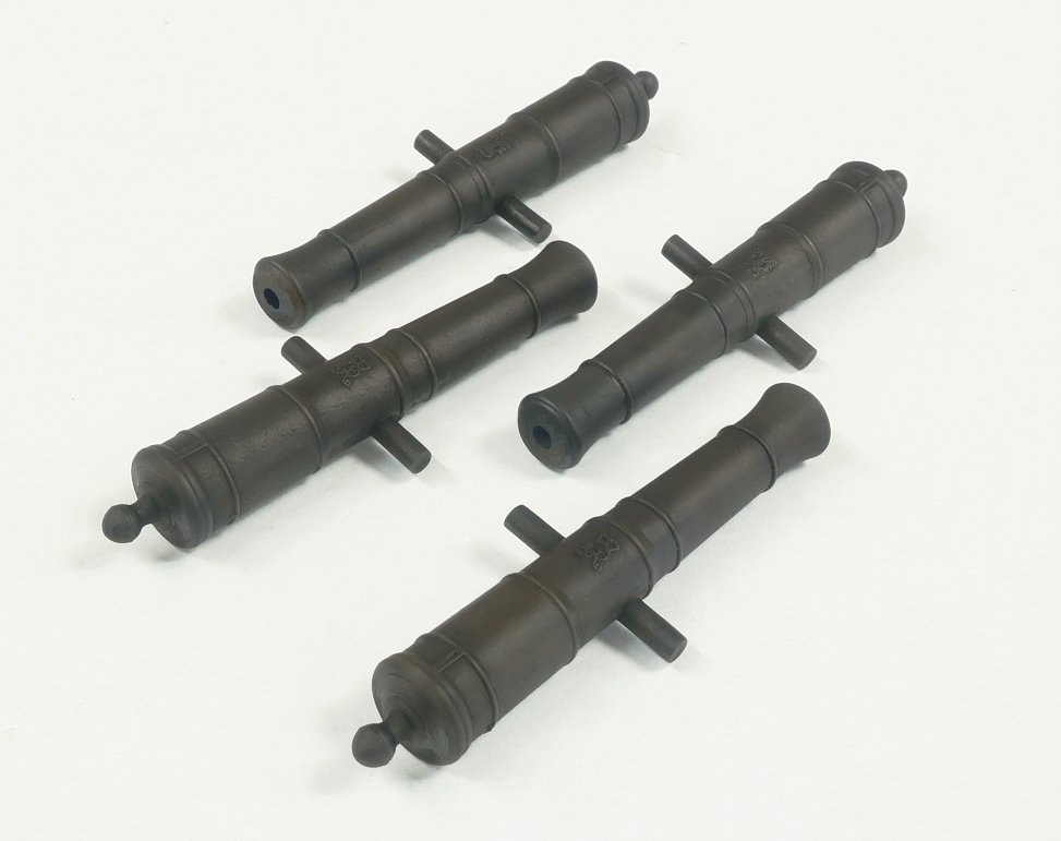
These are ready to go straight out of the package. If you like a more weathered look you can of course do that but these are already blackened and look as though they have a bronzed gun metal finish already. What you see above is what you get...
Now the trunnions are left a bit long so they will fit any carriage width. Just in case you dont use mine. So when you shorten the trunnion to fit any carriage you will probably have to just paint or dye or weather the trunnion ends. A small price to pay for such nice detailed cannon with a proper quality finish.
- palmerit, scrubbyj427, mgatrost and 10 others
-
13
-
Restocking 3D printed Cannon now guys...
I realize some of you have been waiting for certain sizes for a while. Should have them ALL restocked in a few days. These below are hot off the printer.
Please examine the color and finish and texture closely. Most 3D printed guns really look fake and plastic. They look so black and with an odd texture. I am quite proud of the texture and finish on my Cannon.
Hope to have them all back in stock shortly.
-
Stunning work...glad to see you working on her again.
- Ryland Craze, druxey, dvm27 and 2 others
-
5
-
-
-
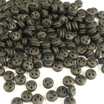
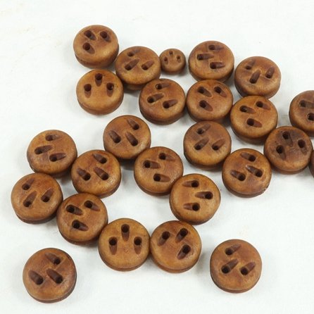
NEW!!!
Lightly Buffed and Ebonized Deadeyes. These are not just dyed black. These are specially dyed and buffed to a dark golden brown color much like real ebony. For those of you who like this finish on their blocks and deadeyes, Over the next two weeks you will see these made available. I am starting with Deadeyes of course.
-
I just found a copy on CD....So I took care of it. I believe this one is sized properly with a cut out for the stem
- KennyH78 and Ryland Craze
-
2
-

Triton by Jerzy
in Cross Section Build Logs for HMS TRITON
Posted
Lovely work Jerzy