

Chuck
-
Posts
9,391 -
Joined
-
Last visited
Content Type
Profiles
Forums
Gallery
Events
Posts posted by Chuck
-
-
-
I have the 5400......
It can be bought here the cheapest that I have seen. There is an instant $25 coupon and free shipping.
http://www.discountcampus.com/cgi-bin/webc.exe/store/st_prod.html?p_prodid=4615
Its about $700
In comparison, the Mocrolux is $500 plus about $45 for shipping....It would have also been some additional sales tax in NJ for me so the cost difference for me was only about $130
For you it would be only about $150 more for the Sherline but you then have to spend $$ on hold down clamps and endmills....the endmill chuck etc....the same is true if you bought the Microlux.
-
I originally bought a Microlux mill to test my block making concepts. At 2500 rpm it was the same as the Sherline buut only about $200 cheaper. I am one of those guys who prefers to use hand tools when making parts for my models. I will take a sharp chisel over a mill any day of the week. But to mass produce parts it just wasnt a consideration so I took the plunge.
After about 6 months, I had successfully set up a method for the mill to cut blocks. I did not find that the 2500 rpm was a problem at all. The Microlux is a heavy and sturdy machine. It performed well. But after 6 months I was producing 20,000 blocks per month. I was probably using the mill more often than most here would ever need. So about two months ago I sold the Microlux and bought a Sherline. It was the same speed. I still dont see a reason to have more speed. But that doesnt mean that if I eventually did upgrade it for more speed I woudnt be happy.
The Sherline is actually lighter built and seems more fragile. The Microlux was a heavy machine and could take a beating....BUT
The smoothness of the Sherline is far superior to the Microlux. The movements of the X and Y tables are incredibly precise and very very smooth. The movement in teh Microlux is a bit primitive and it has a lot of slop. The set up time for the Microlux took so much longer because I had to account for the slop and loose-play in the X and Y axis. You learn to adjust but the results spoke for themselves.
I have had far fewer rejects and much less tear-out of the wood using the Sherline. The smooth precise operation gives you more control to maintain a consistent speed of the x and y tables....this produces a much cleaner part. The number of accessories is also better for the Sherline.
Do I need more power and more speed (RPM)??? I dont really know...but the 2500-2800 rpm on the Sherline seems to be more than enough. The finish and clean surface of the wood (boxwood and Swiss Pear) tells me that the the speed is just fine. I think its important to recognize what the proper feed speed of your work should be and not rush the operations...that will give you a problem. Once again I am really abusing these machines. They are being used 4 or 5 days a week for hours at a time. My 17 year old son uses it with less care than I do...it has been holding up well and I literally make 20,000 blocks per month on it. I cut wood anywhere from 1/16" thick to 3/16" thick...the larger sizes require multiple passes with the endmills....Before making a decision I recommend visiting a friends shop to sit and use theirs and discuss the pros and cons...you have to see and feel the machine at work. Having used both brands in a short time I feel qualified to make the comparison....The Sherline is well worth the extra $200.
Chuck
- WackoWolf, tkay11 and Landlubber Mike
-
 3
3
-
Very nicely done. That top is looking good.
You work fast Dan. Hows the trigger finger?
Chuck
-
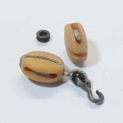
Depending on what they need to be used for.....you can take some thin gauge wire and fold it in half around a drill bit the correct diameter. Then twist the two tail ends together many times which will tighten up the eye and make a screw-like pin. Slip it off the bit when you are done. The screw like tail will really hold when glued into a pre-drilled hole. There will not be any chance you could easily remove it. If you use stell wire you can get really thin stuff and make eyebolts with crazy small eyes. No monkeying around with pliers needed.
Chuck
- molasses, Modeler12, Geoff Matson and 11 others
-
14
-
Very nice work. That is really coming together well. I hope to see in person at a club meeting. Good stuff.
Chuck
-
Nicely done!! The cables do look a bit heavy but that is an easy fix.
Chuck
-
That is looking just fantastic Rusty.
Chuck
-
-
-
Looks nicely done!!!
-
You know where to find me.....3/16" is Ok but its a little wide for the brig. For a brig of this time period, 10" would be ideal. The problem with the kit is that 5/32" wide strips are not common so I had to use the smaller strips. Also with 3/16" strips you may run into problems with bending edgewise. If you are milling your own strips or spiling from wider sheets you shouldnt have an issue with 5/32" being the most accurate. That being said...it will certainly change any planking directives I may have used in the instructions. As far as the nail size...go the smallest you can find. At this scale you would need to use hypodermic needles that are very small to be in scale. They would be small 1/2" nail heads or therabouts. Th eprimary sources on that are scarce to be honest and that is my own best guess.
Chuck
- STSCM, Jack12477 and fnkershner
-
3
-
Just updated the Book Reviews section of the NRG site.....now eight new reviews for you to check out
-
That looks so well done. Congrats!!! I do hope you enjoyed the project from start to finish. Cant wait to see the Syren start taking shape.

-
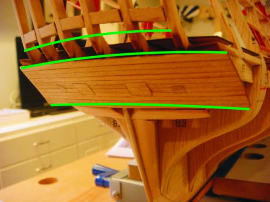
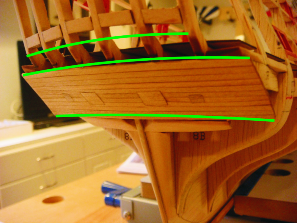
Now that I see it at that angle...its still tough to be sure. But eaxamine the curve of that lower counter as it should mimic the bottom of the transom. The upper counter should be a consistant width when done. One thing I notice is that most folks dont create enough of a curve on the top of the lower counter. It should be curved as such to make the upper counter consistent in height. One way to check this is to place a copy of the transom from the plans....with all the carvings etc. Attach it to the stern frames so you can better see that curve at the top edge of what will become the upper counter.
This will than leave an area between the lower counter and the transom for you to examine. It should be the same height and have a consistent curve to it to match that template.
Hope that makes sense. I placed some green lines on your image to show the curve I think it should look like.
Chuck
- kiwiron, mtaylor, fnkershner and 4 others
-
7
-
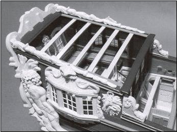
Looks good. Make sure you sand the tops of the sills for the stern windows level. They shouldn't slope down or up....flat and level. Otherwise the model is looking really good. Wonderful work. Try not to rush through the planking. I know that is going to be tough because mid way through...you will want it to be done. Two-thirds done and you will starting mumbling all sorts of things.
-
-
Heres a nice review for folks.......
Scratch Building the Yacht
Utrecht
Instructions and Plans by
Gilbert McArdle
Distributed by: Sea Watch Books, LLC, Florence, Oregon
www.seawatchbooks.com, seawatchbooks@gmail.com
There is no doubt that Gilbert McArdle has become one of the authorities of our time on the construction of models representing Seventeenth and early Eighteenth Century vessels. Mr. McArdle’s latest book outlines the ...........
Open the PDF below to read the full two page review. It really gives you a thorough description if you are considering the project!!
Chuck
-
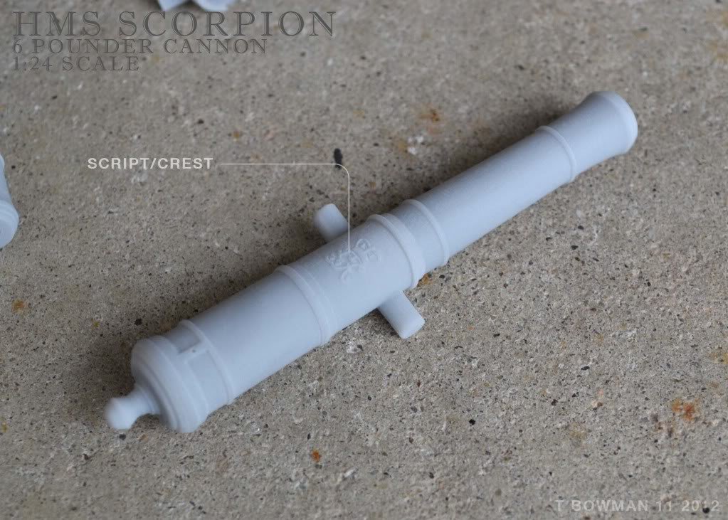
Folks have added additional steps to help reduce the surface texture. It will be a few more years I suspect.
Check out this article.
http://www.kraftwurx.com/forum/25-how-to/572-smoothing-3d-printed-models
Chuck
-
I have seen better although they are slightly larger....1:24 scale. But they are crazy expensive and I dont know what machine he uses
-
-
-
Take a look at the build log underway for this and you will be able to tell. Its all scratch with no timbering sets.
-
Announcing the Model Ship World Ship Kit Database Project
in Wood ship model kits
Posted
I have placed a banner on the right side of the forum and also on the MSW home page...this will ensure easy access moving forward. Adam has been working very hard on this and it will soon be the go to place to find info about ship kits. This will replace that spreadsheet Floyd was referencing. All of us on MSW thanks you..please give Adam any help you can with this if it is at all possible.
Wonderful work Adam
Chuck