Check out our new MSW Sponsor Innocraftsman
×


Chuck
-
Posts
9,630 -
Joined
-
Last visited
Content Type
Profiles
Forums
Gallery
Events
Everything posted by Chuck
-
 Thank you very much for the kind words
 -
Nicely done. It looks good. No need to redo it. Keep going.
- 840 replies
-
- 6
-

-
- winchelsea
- Syren Ship Model Company
- (and 1 more)
-
LOL…its another figure that Larry painted for me a while ago. I just happened to place it on the model and it fit perfectly. It is marvelously painted. I will leave it for the show next weekend but ask Larry to maybe paint me a more appropriate one for the model. I have the waist details next which will complete chapter 11. Then its time to add the lantern and headrails to finish up the hull. Thats it!!
- 1,784 replies
-
- 10
-
-
- winchelsea
- Syren Ship Model Company
- (and 1 more)
-
Beautiful work on the model. You really made it your own interpretation on and its lovely
- 112 replies
-
- 3
-
-
- Cheerful
- Syren Ship Model Company
- (and 1 more)
-
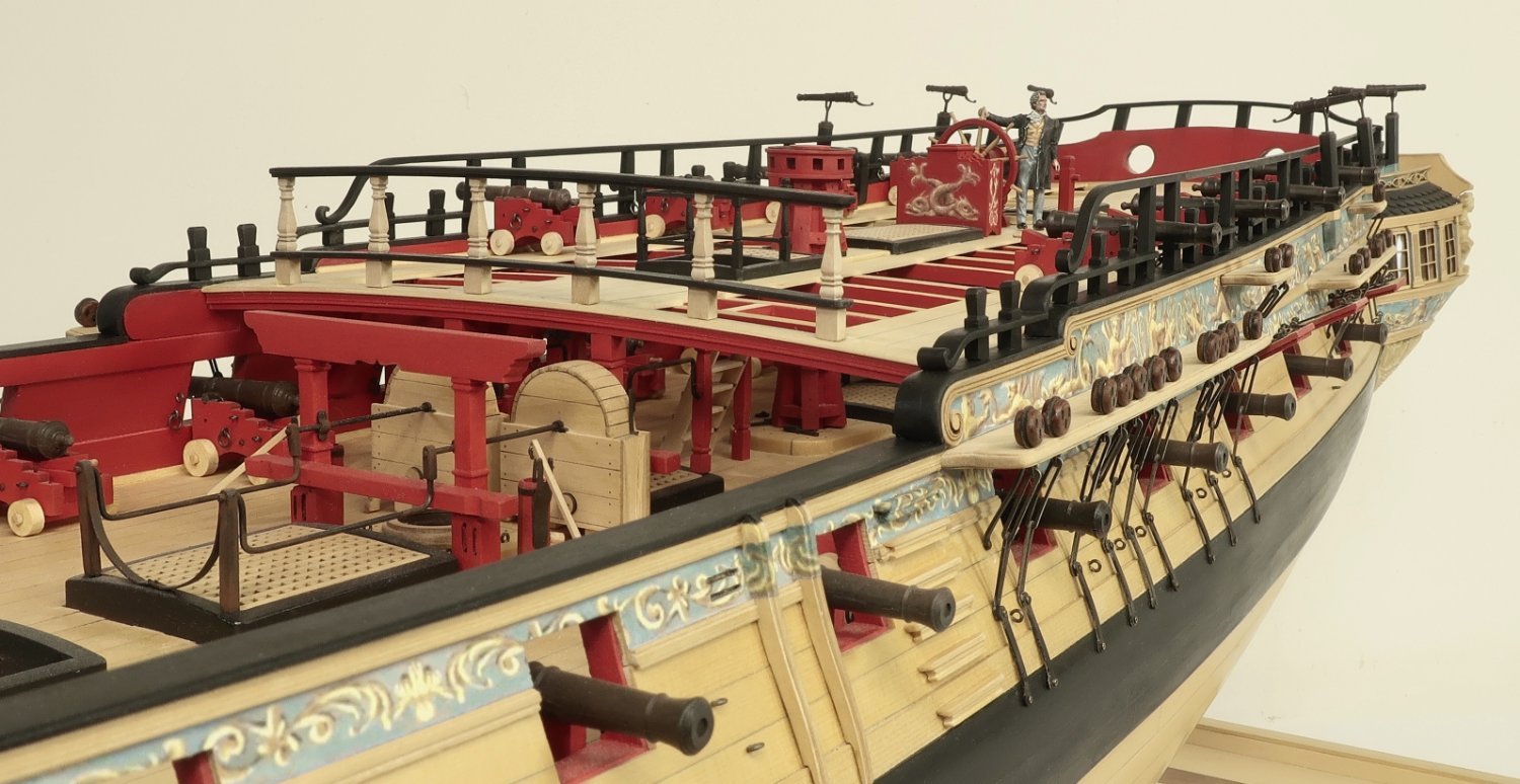
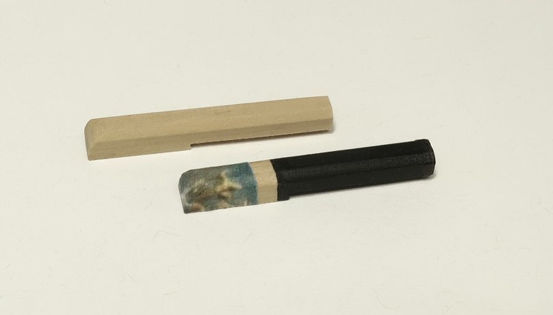
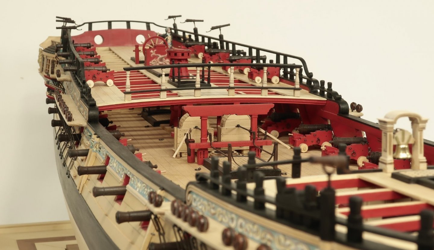
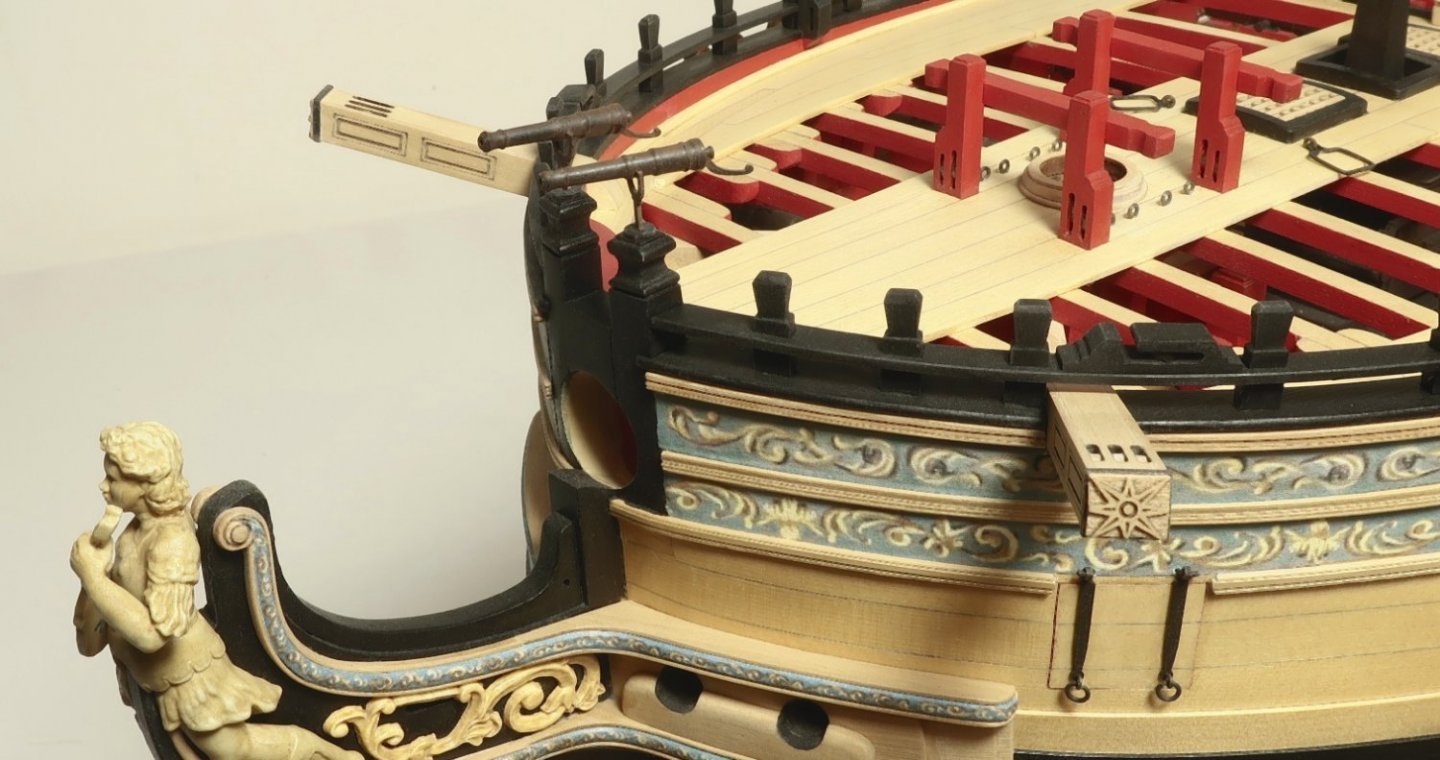
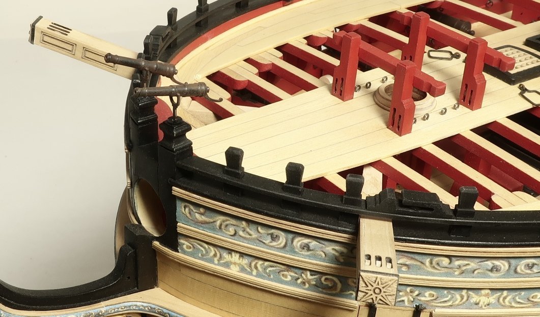
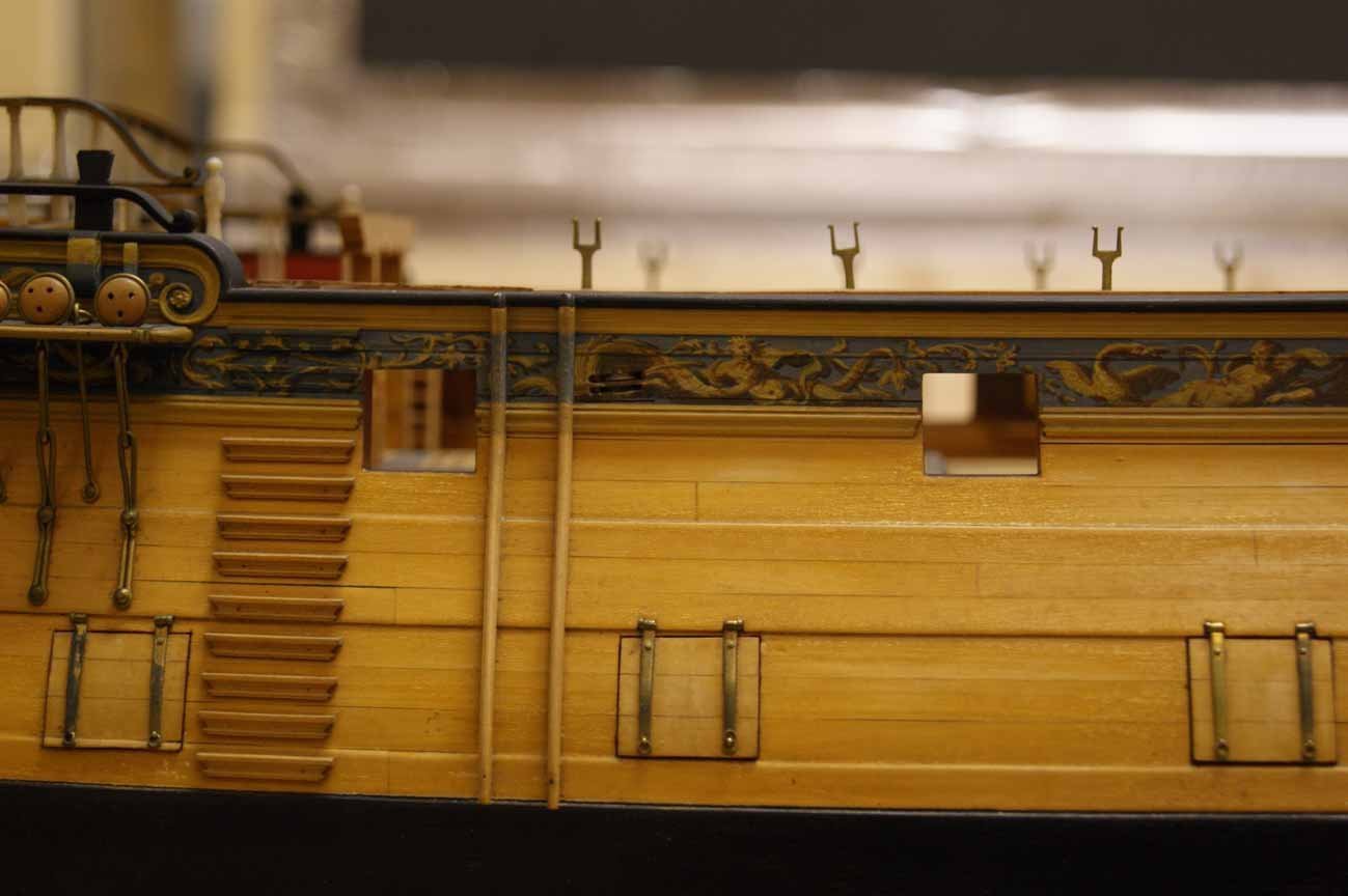
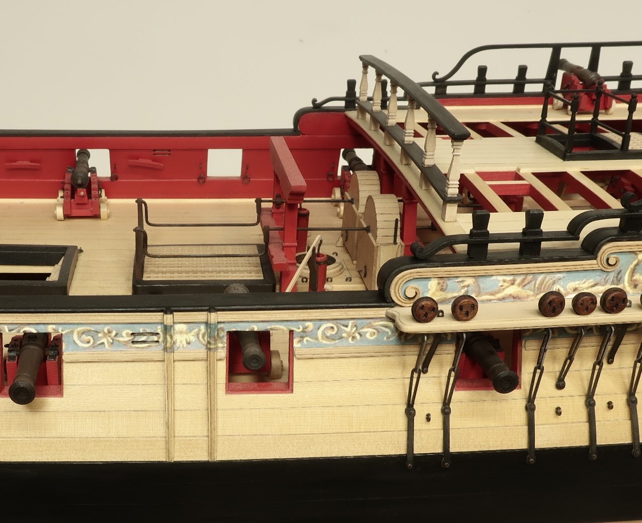
The swivel stocks are made from a 5/32" x 532" strip. Their lengths are all different and should be taken from the plans. They will be sanded or files on all for corners to make them 8 sided. BUT....not where they sit against the hull. Here you leave that prtion flat on the entire side. You can see one pair of swivel stocks below. One is dressed and the other undressed. Not the flat side. Measure on you model the length of the flat portion to fit against the hull. From the top of the shear down. The bottom was rounded off as well. The hole in the top was made with a #65 bit for the swivel guns and a thin band of black tape wrapped around the very top. You have to do a lot of measuring from your model to determine the end of the black and the frieze allowing for a natural area to match where the molding is. Just take your time measuring and marking. The friezes were applied as usual after printing them on tissue paper. They were applied with a glue stick and I did my best to match the pattern but it isnt that critical. Some photos showing the stocks installed. I notched away the molding and overhang of the shear to accommodate them. I also did my best to make sure they were vertical but also matching the angles of the rails. They will follow the shape of the hull as well and lean a bit to match the curvature of the hull. The aft-most swivel stock also angles against the forward side of the transom. This makes it look a bit odd depending on the angle but the original drat shows it this way rather than vertical like the other stocks.

- 1,784 replies
-
- 35
-
-

-
- winchelsea
- Syren Ship Model Company
- (and 1 more)
-
They are basically the same or at least they will be on my model. The weathering powder wears off and dust gets on them and it all evens out.
- 1,784 replies
-
- 3
-
-
- winchelsea
- Syren Ship Model Company
- (and 1 more)
-
Not for about a week or so maybe longer. waiting on an order of more acrylic sheets.
- 1,784 replies
-
- 2
-
-
- winchelsea
- Syren Ship Model Company
- (and 1 more)
-
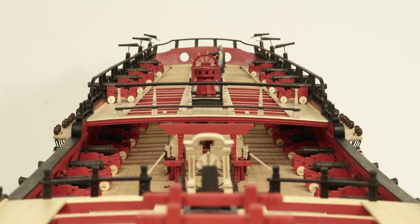
More dealers choice....swivel stocks On the contemporary model there are two swivel stocks on each side of the fcastle. On the original draft there is only one. Only the stock forward of the shrouds is shown. Its up to you really. I am going to omit this swivel stock aft of the shrouds because it is not shown on the original draft. I also think it hurts the graceful flow of the rail into the waist. But its up to you. In addition, the contemporary model does not show the aft-most swivel stock along the qdeck. But it is shown on the draft making it 3 per side. I am just pointing out some discrepancies in case any of you notice it. It would be fine to show all ten swivel stocks that I show on our model plans and the two on the bollard timberheads. But if you agree that the second pair on the fcastle would be visually problematic, you can omit them too. And also, the stocks on Amazon are completely round. Those on the Winnie Contemporary model are six sided. BUT...for me it is much easier to take a 5/32" x 5/32" strip and make it 8 sided by sanding the corners. I follow the 7-10-7 formula for doing so. Although its easy enough if you are careful to just free hand it. Omitting that one pair of stocks on the fcastle also follows the arrangement shown on the Amazon and some other contemporary models. Below. As I have mentioned, the Amazon is one of my inspiration examples while working on the project. I believe you can see the similarities between it and our project.
- 1,784 replies
-
- 17
-
-
- winchelsea
- Syren Ship Model Company
- (and 1 more)
-
This is simply not true. At least not in the USA. All commercial products must be mailed and shipped at the parcel price. The USPS will not allow any product to be shipped by a known commercial seller just an an envelope. I know first hand because I have tried. Many dont know this and the seller would face stiff penalties and or refusal to ship from the Post Office if caught. Sorry but you are just wrong. One reason is that any stiff items will jam the new sorting machines. Only envelopes can be put in them and they bend through the machine rollers. When you put anything hard or metal in the envelopes it jams the machines and believe me you hear about it if you are a commercial shipper. Parcels are NOT put through sorting machines like the envelopes are...or they are put through different ones not likely to jam. In the US the cheapest parcel rate for commercial shipping is around $5.50 Up to 8 oz. If its going international it varies...but you are looking at $14 - $22. The cheaper number is basically just Canada. I have had angry emails that shipping 1package of large triple blocks which cost $6 when sent to Europe would cost $22 to ship. I get called a crook all the time. But folks are just so wrong and have no idea how it works for a small business. No way around this unless you are Amazon and get a huge break from the post office. Small guys have to pay full rate every time. So any of you guys in the US that get angry about not using a first class stamp to mail a few packages of blocks or rope....or "brass pins", please understand that this is not 1950....you cant do that any more. Now if that guy is charging $16 to ship within the same country like the USA he is absolutely ripping you off. But $7 - $10 is pretty standard to cover packaging etc. Unless you are Jeff Bezos.
- 47 replies
-
- 22
-
-
Thank You very much!! 😄
-
Thats interesting but I am following a few other contemporary models. They have them all set out. Amazon in particular is the model I am using for swivel gun replication. She had twelve according to records so why not just show them all. I have them all made anyway.
- 1,784 replies
-
- 8
-
-
- winchelsea
- Syren Ship Model Company
- (and 1 more)
-
They are available in brass but you wont be able to drill the hole in the arse end to easily for the handle. The brass ones are in my store and are available as just the barrels with trunnion pin. They are 13/16” long. You would have to make your own bracket and figure something else out for the handle though. the resin is easy to drill. The resin version is actually cast from the brass barrel which was used as the master. They are identical in shape and size.
- 1,784 replies
-
- 7
-
-
- winchelsea
- Syren Ship Model Company
- (and 1 more)
-
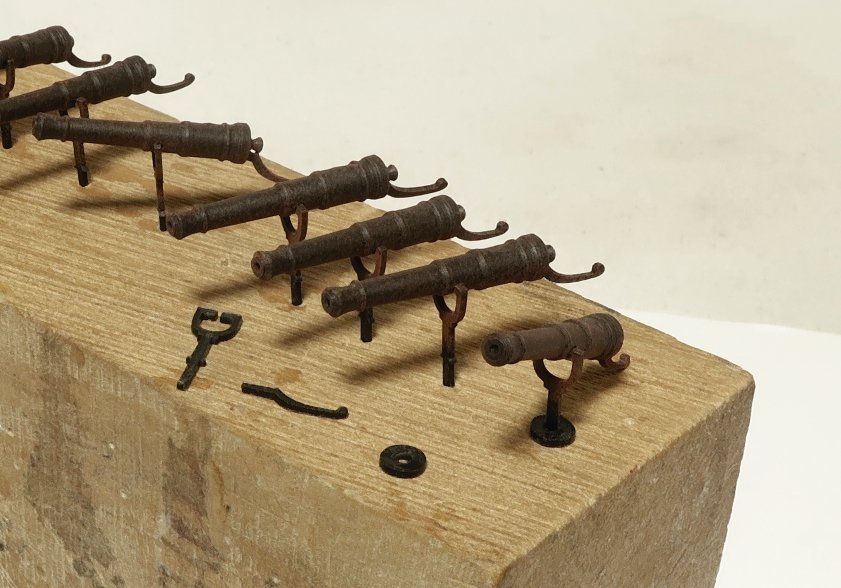
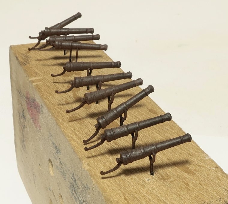
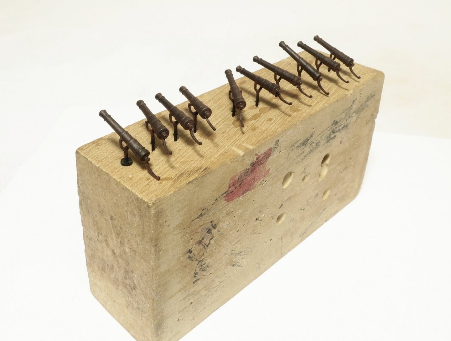
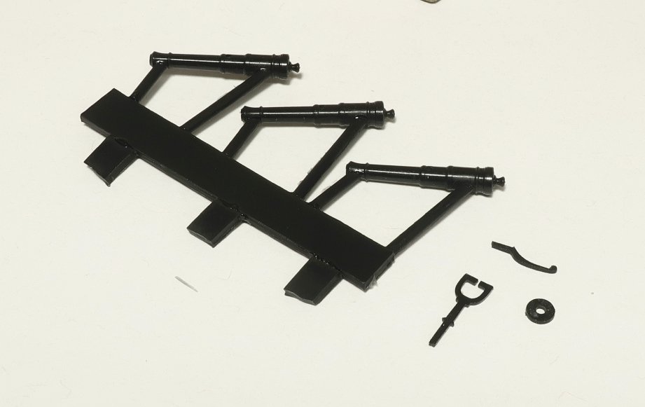
Swivels... The swivels are cast in resin as you can see above. They come on a spru. You need to cut them free with a flush cutter and sand off the nubs. These are not drilled for the trunnion. You need to drill them thru with a #65 drill bit. That is the perfect size. You also need to use the same bit to drill a hole into the back end below the button. This is for the handle. The handle and yoke ....or bracket, is laser cut out of acrylic. Just glue the handle into the hole in the back end you drilled. Hopefully it was centered with the trunnion holes and below the button. The bracket is easily added. Slide the muzzle end into the space of the bracket until its lined up with the trunnion holes. Then gently pull the bracket down so the fork start spreading apart. It will flex and snap right into the trunnion holes you drilled....that is if you used a #65 bit. The small disc you see in the photo is for the tops of the swivel mount. You will add the disc on top before inserting the bracket into a hole you drilled in the wooden mount. These are quite tiny and hard to photograph....here are the swivels assembled and weathered. I sprayed them with matt fixative or dull coat first and then applied some weathering powder. I didnt make the swivel mounts for the side of the hull yet. But there are also two swivels up front on the bollard timbers. I drilled the #65 hole in the top of the timberheads. Then I added the acrylic disc...no glue needed. Just position it and slide the swivel into the hole locking the disc in place. These will be sold in packages of six resin swivel guns along with the laser cut parts for the bracket and handle and discs. Now to make those swivel mounts for the remaining ten.
- 1,784 replies
-
- 30
-
-
-
- winchelsea
- Syren Ship Model Company
- (and 1 more)
-
Thank You very much!!!
-
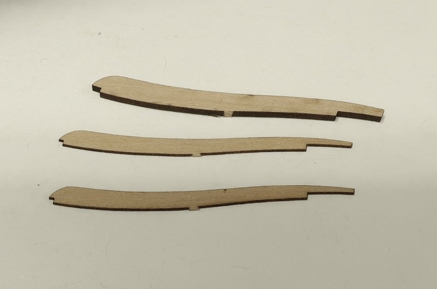
Basically its the same way you printed the flags for Cheerful. You tape or glue the edges of the tissue paper onto an 8 1/2 x 11 sheet of paper. Just around the edges. Then stick it in your ink jet printer. And print. Its not difficult. the scraper profile can be taken from the plans. Just look at the steps and you will see the shape. Its why we have plans. I will supply two 15” long strips of course. Enough to make over 25 steps even though you only need 12. i just spread a glue stick on the back of the tissue after cutting the frieze area I want. Then its just a matter of being careful…lay it on the piece and use a blunted toothpick to lightly tap it down. You will learn by doing!!! It wont go right the first time…but after some practice it will seem easy to you.
- 1,784 replies
-
- 5
-
-

-
- winchelsea
- Syren Ship Model Company
- (and 1 more)
-
Thanks…it is so weird looking at the model now. For several years it looked very different without the channels and fenders etc. Those outboard details really change the whole look of the model. I cant imagine what its gonna look like after the headrails are all done. Again probably Very different I imagine.
- 1,784 replies
-
- 8
-
-
- winchelsea
- Syren Ship Model Company
- (and 1 more)
-
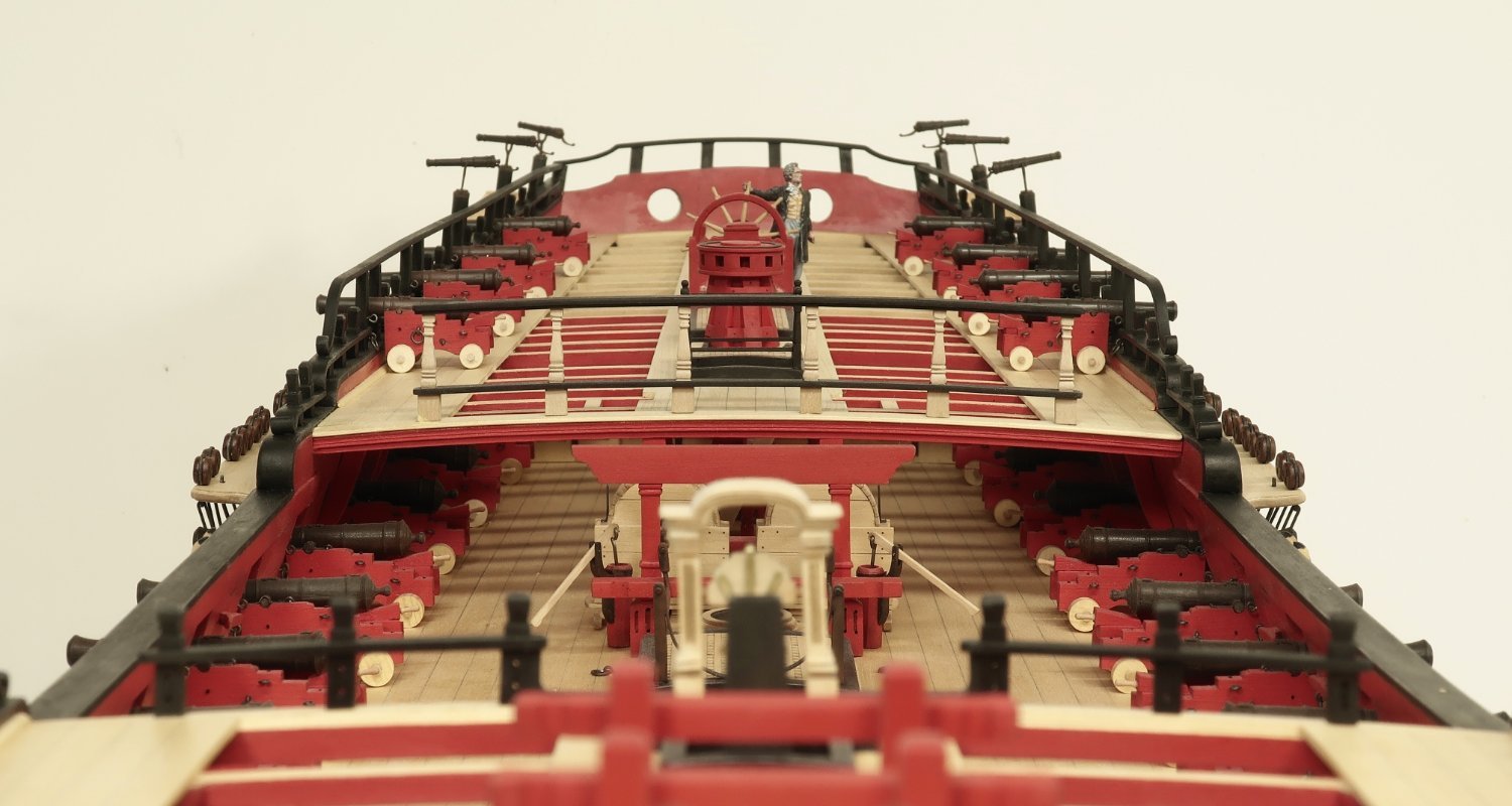
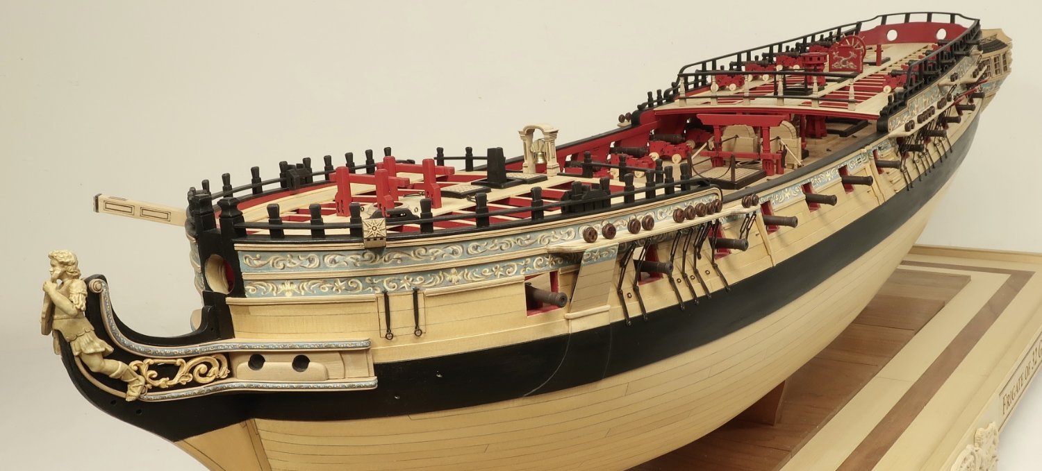
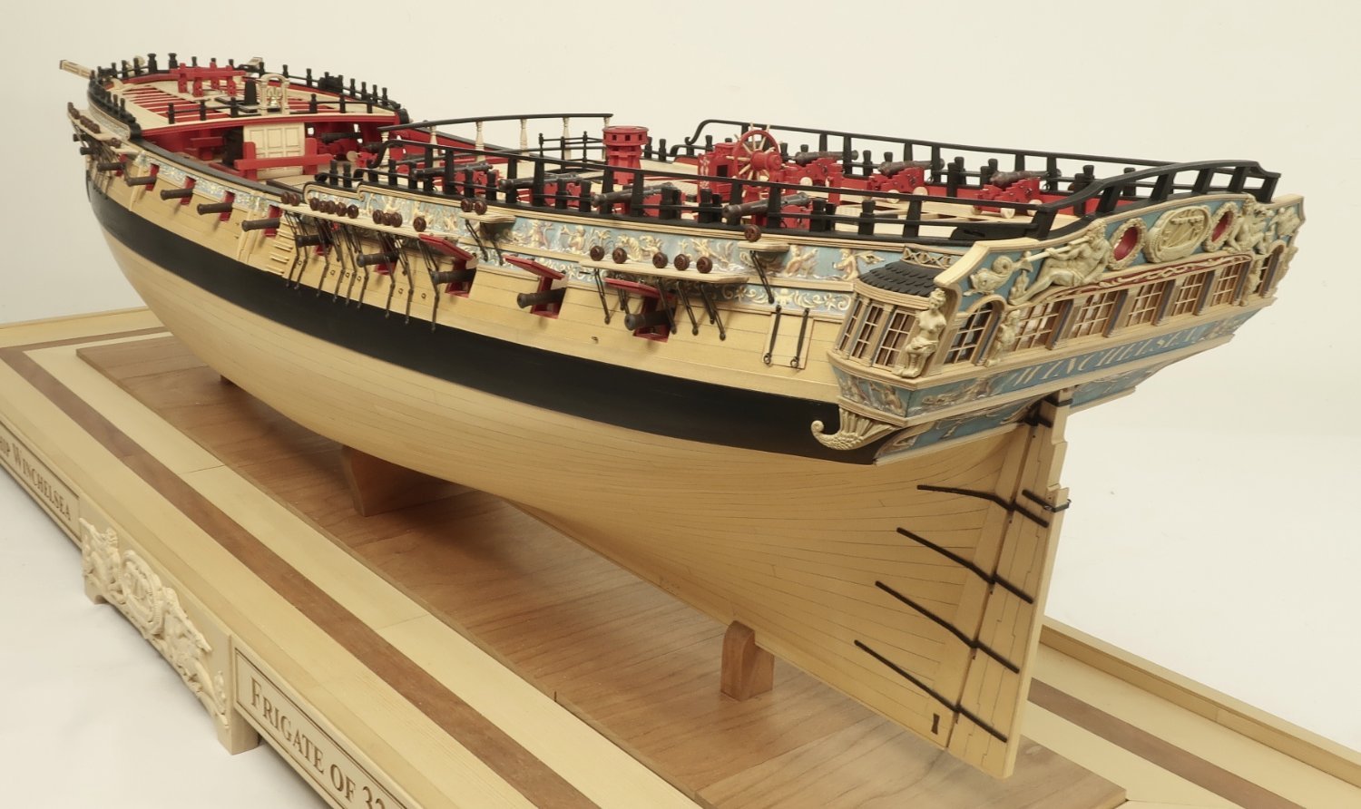
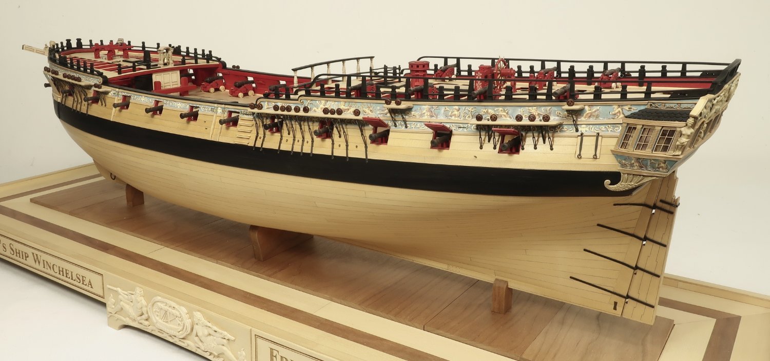
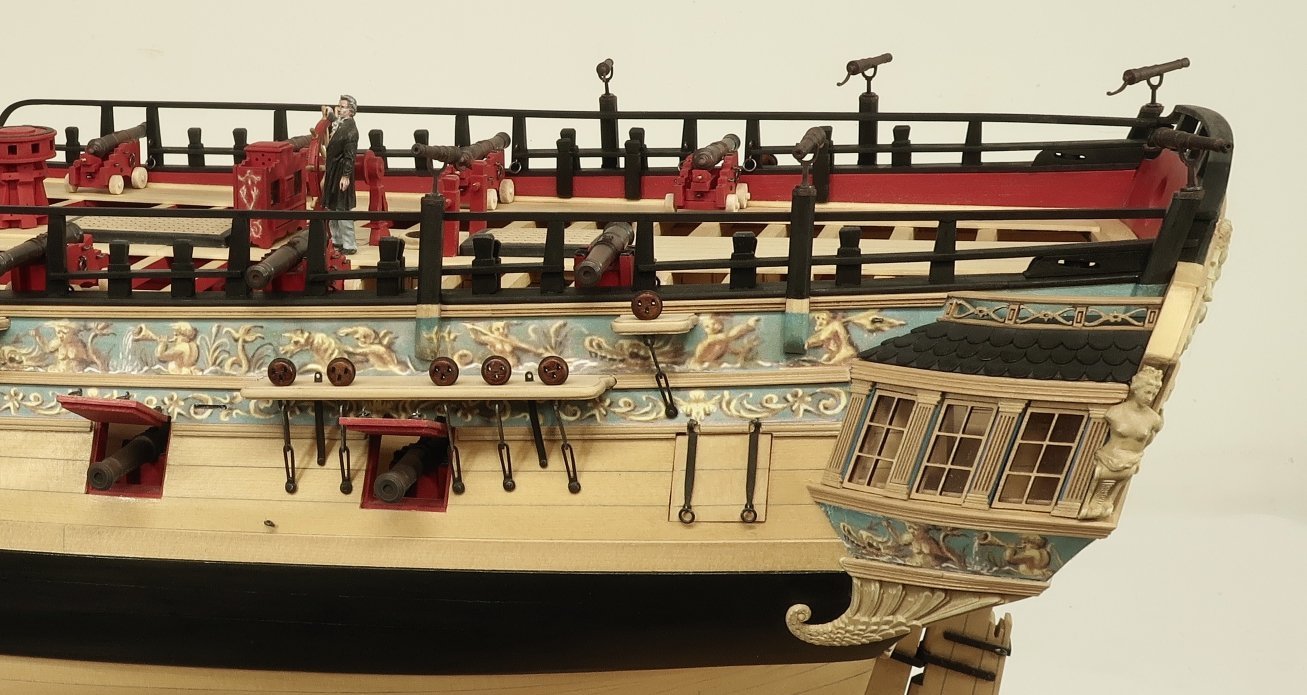
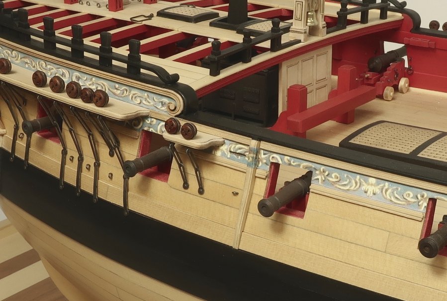
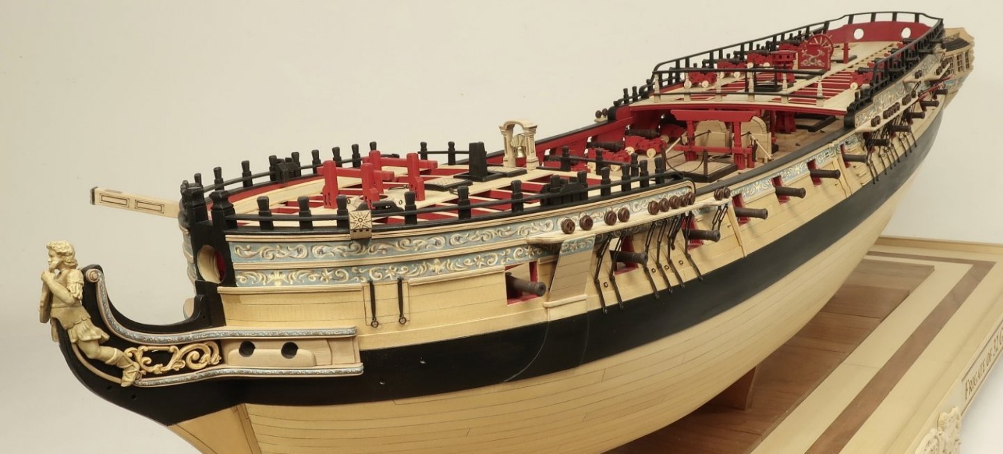
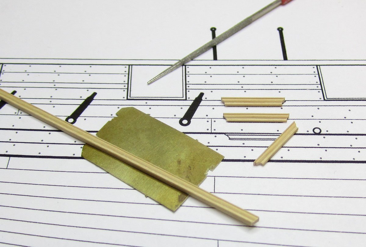
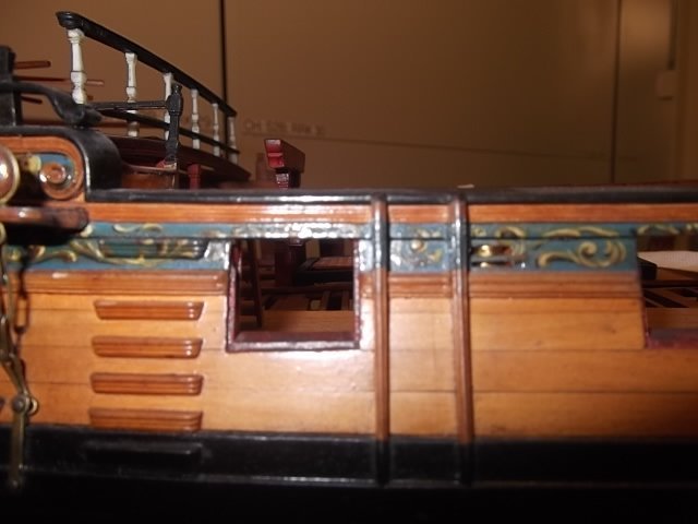
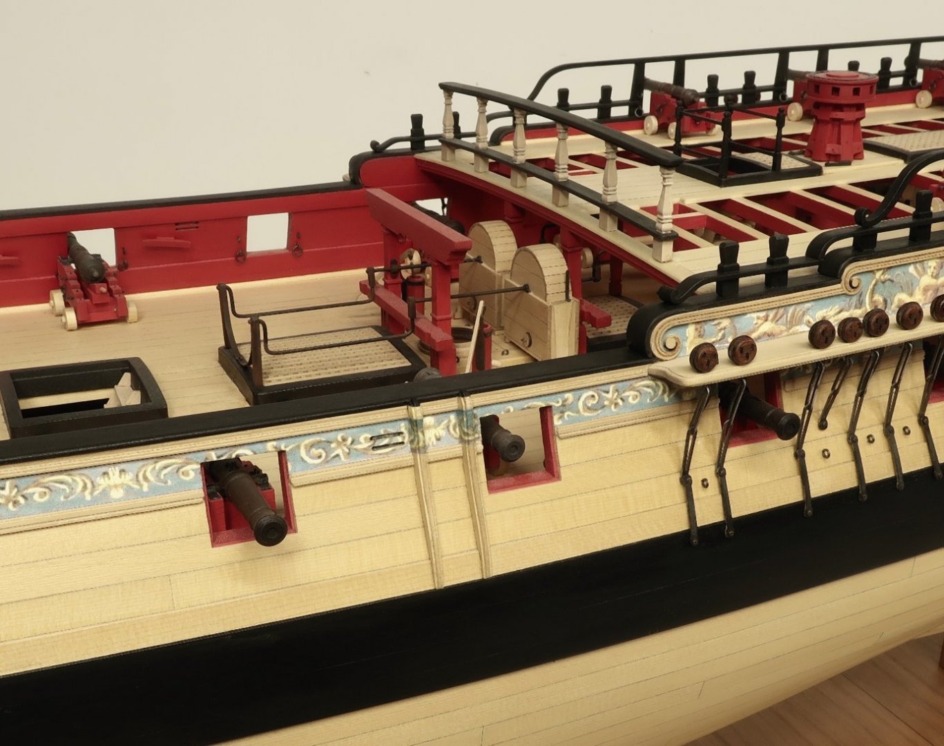
The chesstrees are made just like the fenders. No need to show it being glue together. The middle layer is slightly wider to accommodate a sheave. The one thing I did do was round off the sheave before gluing up the three layers. It is difficult to see the sheave in the photo but I will try and get a better picture. The boarding ladder is pretty straight forward. No laser cut parts here. I made a scraper for the profile....then scraped a strip of boxwood. Then I used some files and chisels to shape the sides. There is no silver bullet here. The best way to make these is to do it by hand like this. I used a 3/32" x 5/64 strip of boxwood. Here is how I made them on Cheerful and I made these the exact same way. The profile is a little more fancier however. Here is what they look like on the Winnie. I opted to folow my reconstruction for placement. It wasnt fun cutting away the molding neatly. But I managed it. You can do the same or opt for the way it was done on the contemporary model. Its up to you. I printed the frieze for the top step on tissue paper. I used a glue stick to adhere it. Then I carefully used a toothpick to push the frieze into the recesses etc. It did require some paint touch up on the sides but I am very happy with the results. Make sure you bevel the back side of each step so the top is flat. Otherwise the top face of the steps would tilt one way or the other. I still have the starboard side to do. Here are some photos of the model with the exterior almost completed. We only have the swivel mounts left after the ladders are done. I added all the eyebolts shown on the plans which were made from 24 gauge wire. Swivels will be next once I complete the ladder on the other side. She's getting there!!!


- 1,784 replies
-
- 33
-
-
-
- winchelsea
- Syren Ship Model Company
- (and 1 more)
-
I am always inclined to follow the draft but after checking all of the contemporary models in our Gallery and more on the NMM site, they all seem to leave the molding intact. They preferred to model it differently than the drafts. So as stated, you can go either way although I suspect the drafts were more accurate. The top step will need a frieze. I may paint it blue to match and then use a printed frieze on tissue paper on the center portion. So a combination of painting and tissue paper.
- 1,784 replies
-
- 5
-
-
- winchelsea
- Syren Ship Model Company
- (and 1 more)
-
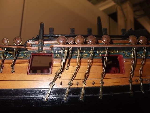
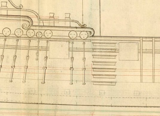
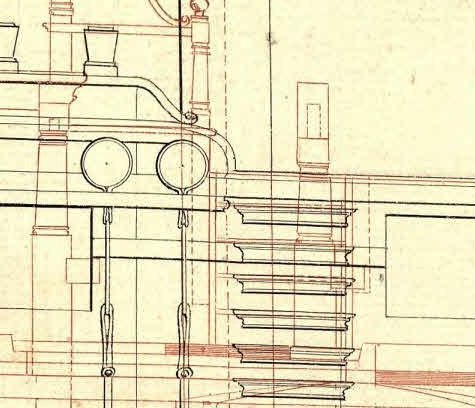
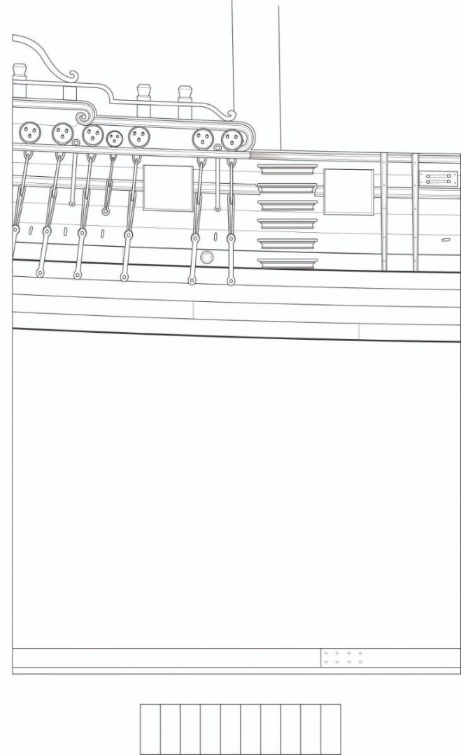
Just an FYI.....its one of those things.... On the Winnie contemporary model the ladder or boarding steps are kind of funky as far as spacing goes. See below. There are 5 steps below the molding and one above it. This does not match the original draft. But it is very typical of contemporary models...here is another that does the same thing. It would be fine to do it this way. The molding is supposed to be cut away to make room for a step. But I imagine the contemporary builder didnt want to break the nice run of the molding perhaps? If you look at the original draft it is very different however as well as our model plans. I wonder why the deviation? The plans show the molding cut away to facilitate an even distribution of ladder steps. Also note how on the steps follow the sheer on the models but are actually flat on the draft although its hard to tell. I am not sure which way I will go yet. But you have some choices. I dont want to be the guy to randomly pick one for the group yet any will work and be historically correct "of sorts", based on these contemporary sources. Two drafts for the class....Note that one even has seven steps. With an extra actually on the wales. The bottom pic shows how I reconstructed this but its basically dealers choice. I dont know why the contemporary model builders didnt cut away the molding for the step. But do you guys have any thoughts on this...or preference.
- 1,784 replies
-
- 8
-
-
- winchelsea
- Syren Ship Model Company
- (and 1 more)
-
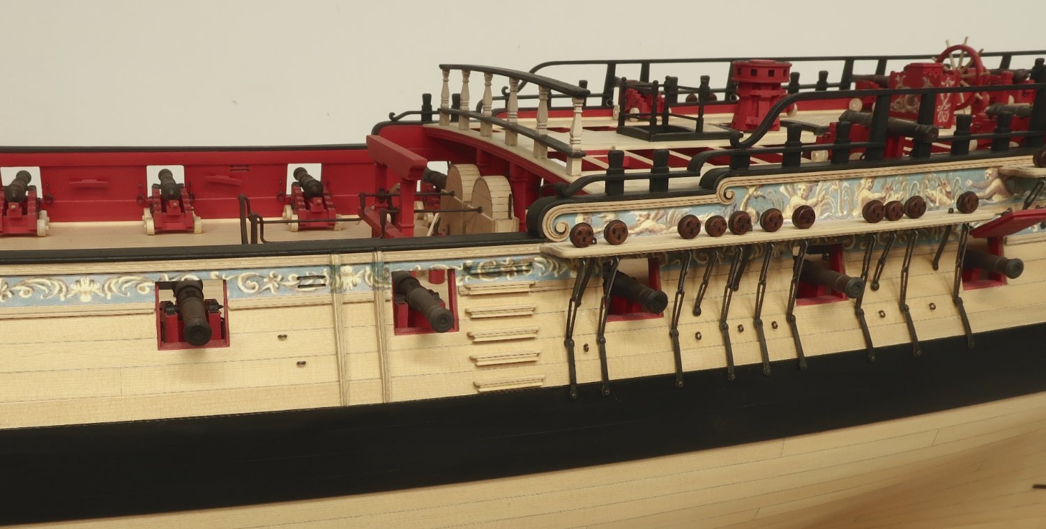
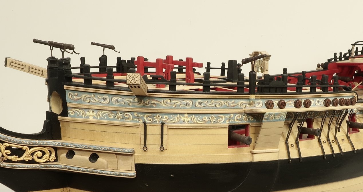
Fun with fenders today!! Fenders may seem like a small detail but it is very important. These small pieces can really hurt the appearance of your model if done poorly. These are laser cut for you just like the channels. They are done in three layers. Very thin outside layers is the key. But one often overlooked detail is the fact that the fenders do taper thinner as the work their way lower on the hull. That is when viewing them head on. To add this detail will elevate your model as well as getting the beaded edges made by the layers nice and neat. The center layer had the char removed first. Then I thinned down and tapered them towards the bottom. Only then did I add the outside layers. After using some wipe on poly I set them aside. But now it was time to carefully chisel away the molding on the hull to accept them. Do this carefully to get nice tight seams. I glued the fenders in place first on the hull and then added the fries so I could carefully match the pattern as best I could. Then I painted the top black to match the sheer cap. I hope you can see the nice beaded edges and the taper. I will note that I used tissue paper this time to print the friezes. I wanted it very thin so I could push it into the beaded edge with a dull toothpick. I used a glue stick for the adhesive. It will be almost impossible to match the pattern but its more important to just get some neat color on the fenders that match. Any questions or comments.???? Now its onto the other side...and then the chesstrees which are done exactly the same. The chesstrees have a sheave through them however and you will see that soon enough.
- 1,784 replies
-
- 22
-
-
-
- winchelsea
- Syren Ship Model Company
- (and 1 more)
-
For small pieces I prefer the glue stick. I can get more control. Even if I apply with a toothpick. Less messy.
- 607 replies
-
- 2
-
-
- winchelsea
- Syren Ship Model Company
- (and 1 more)
-
Nicely executed. Beautiful rail uprights. Nice and clean.
- 607 replies
-
- 1
-
-
- winchelsea
- Syren Ship Model Company
- (and 1 more)
-
Looking good Mike!!! Slow and steady.
- 607 replies
-
- 1
-
-
- winchelsea
- Syren Ship Model Company
- (and 1 more)