Chuck
-
Posts
9,703 -
Joined
-
Last visited
Content Type
Profiles
Forums
Gallery
Events
Everything posted by Chuck
-
 I am really not sure what you are asking. It depends on what I am using it for. For planking sheets used to rip planking strips ....yes I will cut cherry or AYCedar that way. But other types of wood may be different. But on Cherry and AYC that is the best way to get grain free clear strips for planking....
- 1,784 replies
-
- 1
-

-
- winchelsea
- Syren Ship Model Company
- (and 1 more)
-
Its getting crazy now…yellow cedar used to cost me $10 per bf. As of this week after placing an order it has shot up to $19 per bf. This is for the primo stuff which we need. You can buy garbage Cedar wood cheaper but would have to throw half of it in the fireplace. boxwood and pear is way up there in the USA. Its actually cheaper for me to order a few hundred pounds of pear from Europe and have it shipped to me than buy it in the states. Its nuts. I havent raised my prices for my products yet over the last six years but sadly after the wood prices almost doubled now…I may have to. Chuck
- 1,784 replies
-
- 4
-

-
-

-
- winchelsea
- Syren Ship Model Company
- (and 1 more)
-
Very nice save. That is a very tricky part of the build. A square tuck is always a challenge and yours looks really good.
- 113 replies
-
- 1
-
-
- Cheerful
- Syren Ship Model Company
- (and 1 more)
-
I just lifted the stern and put the buildboard on a six inch block. That worked for me.
-
Ihave no idea...but let us know how your experiments work out.
- 1,784 replies
-
- 1
-
-
- winchelsea
- Syren Ship Model Company
- (and 1 more)
-
I use either regular copy paper with my ink jet or when I want to go really thin so you cant see the paper at all I use tissue paper. Chuck
- 1,784 replies
-
- 2
-
-
- winchelsea
- Syren Ship Model Company
- (and 1 more)
-
Yes...they work great BUT.....BUT, the adhesive is very strong and it isnt easy to reposition and slide them into place nicely. Thats why I prefer to use a glue stick which has an open time and lets you slide them around. Chuck
- 1,784 replies
-
- 3
-
-
- winchelsea
- Syren Ship Model Company
- (and 1 more)
-
That is better answered by the others. But every part or nearly so is laser cut.
- 1,784 replies
-
- 2
-
-
- winchelsea
- Syren Ship Model Company
- (and 1 more)
-
Slow and steady…they will fit. You just have to get the knack for it.
- 1,784 replies
-
- 3
-
-
- winchelsea
- Syren Ship Model Company
- (and 1 more)
-
Nicely done...
-
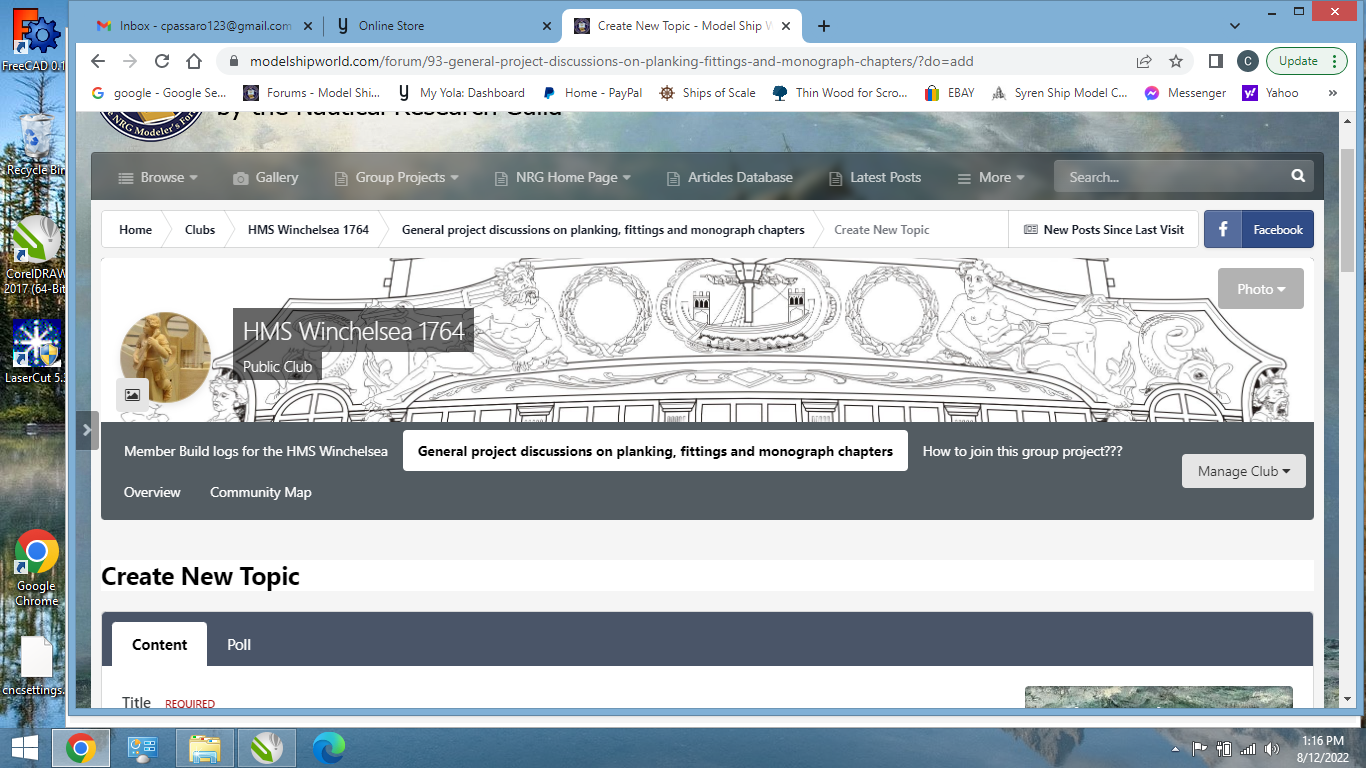
https://modelshipworld.com/forum/93-general-project-discussions-on-planking-fittings-and-monograph-chapters/ That link above takes you to a tab that can be found above the build logs.......see it highlighted in white below in this screenshot. There seem to be a lot of folks who have forgotten about this areafor the group or recently joined and didnt see it mentioned on the "how to join this group" topic. So browse anything you might have missed and feel free to join any of these IMPORTANT discussions. Also start new ones if you need to because its easier to find a discussion on a particular Winnie topic here than hunting through all of those build logs. This area is being way under utilized as a source. Chuck
-
Looking good....dont forget to simulate the caulking between deck planks. You are well on your way.
- 113 replies
-
- 1
-
-
- Cheerful
- Syren Ship Model Company
- (and 1 more)
-
Nope I dont actually know. But its not anything you will need. But I am sure you can figure it out from the original draft if you find a reason to need it. They are NOT level across that bulkhead and are purposely at different heights and angles.
-
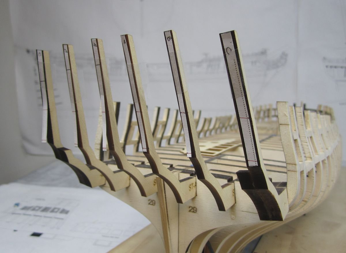
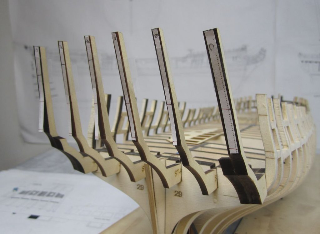
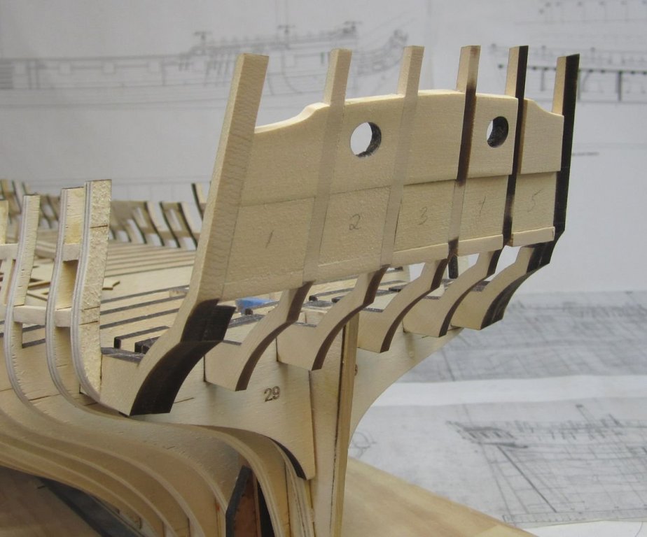
Some of you guys are way overthinking these stern set ups. The best way to line things up and get things level is to work from the other side. View the stern frames and fillers from the outboard side. One step at a time working from the inside two stern frames placing the fillers and frames in position. Use the template to mark the heights ahead of time. I see so many errors in your placement you will certainly have issues with the way you are proceeding. Just attach each template to each stern frame to establish the heights for the sills and fillers. Then proceed to place each filler and sill between them working from the inside out.... Place the number 3 filler first and then the sills above and below it... Then proceed to #2 and #4 And lastly 1 and 5. Getting a visual from the outboard side at each step. Chuck
- 389 replies
-
- 6
-
-
- winchelsea
- Syren Ship Model Company
- (and 1 more)
-
Looks great Fred.
-
Yes they do...they will be able to mill to the sizes you need.
-
That looks exceptional…really nice work
- 99 replies
-
- 1
-
-
- winchelsea
- Syren Ship Model Company
- (and 1 more)
-
That will happen sOmetimes. But you recovered nicely. Onward and upward as they say.
- 389 replies
-
- 3
-
-
- winchelsea
- Syren Ship Model Company
- (and 1 more)
-
It looks OK. Its hard to tell in photos if everything is lined up where its supposed to be but it looks just fine. Chuck
-
Looks nice...one thing I do recommend is that the blue paint on the stern transom shouldnt be used at full brilliance or saturation. Its too bright and blue....Before you add anything else I do recommend that the blue paint there be toned down with just the smallest amount of white mixed in to it to lighten it up. Iamof course suggesting some white mixed with the blue on your pallet before you paint. Just a smidgeon....it helps a lot. Chuck
- 840 replies
-
- 2
-
-
- winchelsea
- Syren Ship Model Company
- (and 1 more)
-
I am a big proponent for not mixing wood types. My preference is always to use the same wood for hull and deck. But I am old school and tend to look at and admire the contemporary models which mostly did the same.
-
Beautiful work. A very nice planking job indeed.
-
That looks great Ben....how did I miss this post. Wonderful progress. Chuck
- 399 replies
-
- 2
-
-
- winchelsea
- Syren Ship Model Company
- (and 1 more)
-
Absolutely yes… Chuck
-
A nice fresh start!!!