
Supplies of the Ship Modeler's Handbook are running out. Get your copy NOW before they are gone! Click on photo to order.
×
Chuck
-
Posts
9,447 -
Joined
-
Last visited
Reputation Activity
-

 Chuck got a reaction from GrandpaPhil in Sloop Speedwell 1752 by Chuck - Ketch Rigged Sloop - POF - prototype build
Thank you very much!!!
I am just doing busy work...planking those aft platforms. But I thought this small detail was worth mentioning. Maybe some of you will think this is a good tip to use on any model.
The lower aft platform is planked first following the plans and templates provided. But as seen on many ship models there are scuttles which have rings for handles. Similarly you see these type of rings used for the gun tackles on decks etc. Most folks will make a split ring and then insert this into the eye of an eyebolt. You have seen this a million times.
The photo below shows just that. Look at the bottom row. On the left is what you typically see. The split ring on an eyebolt. Nothing wrong with this as everyone does it this way. But even when the eyebolts have smaller eyes you will end up with so many unsightly rings on deck or on your scuttle lids that look out of scale and sticking up. Yes, you are supposed to sink the eyes part-way into the deck which is a real pain. But even then, it looks very odd to me now after examining so many contemporary models.
So to the right is a solution for this which I keep meaning to post... but always forget to.
The split rings in this case are made from 24 gauge black wire. They are made as usual...wrapping many times around a #47 drill bit and sawed off to produce a 15 or 20 rings.
Rather than make and use tiny eyebolts I just take a small length of thinner 28 gauge black wire and make a small bent "V". This makes it easy to handle and slip the split ring onto. Then I crimp the 28 gauge wire tight around the split ring with a small pliers. Its very simple indeed. Squeeze the two ends together and snip off the bottom on an angle so you have a point. It looks almost like a cotter pin of sorts. This is slipped into a hole drilled on deck or in this case the scuttle lids.
I saw this done in my favorite book. "Legacy of a Ship Model" by Rob Napier. During his restoration of the Princess Royal model he took the model apart...I mean all of it. In the book there are so many photos of these items which show the way the contemporary model builders made their parts. This is how the contemporary builder made these on that model (250 years ago) and after carefully examining so many other contemporary models I believe most of them were made just like this. There is an excellent photo of the contemporary version of one of these in that book....along with countless other gems showing how those guys did stuff back then. Rob had to make more of these for his restoration and used the exact same method of course.
This makes the handles and rings look so much more to scale. No more pesky eyes sticking up that are too large all over the deck for the crew to trip over. Its a small detail but I thought worth mentioning now that I remembered to do so. At least I hope you think so. Its the small details that make a difference when you add them all up...
Lastly I also made the mizzen mast coat as you can see. Its made in the same way as on the Winnie. Three layers. The middle layer is rounded off and the char removed. Then the top and bottom layers were added after removing the char from those. The mast coat is not glue down permanently. Its just lightly tacked with some rubber cement. You may have to move it when trying to position the mizzen mast later. So dont glue it down permanently yet. The hole on deck is slightly larger than that of the mast coat...so you can move it any way to accommodate the mast later. NOTE: The mast coat was later changed here to be Octagonal. The lower masts are not round and I discovered this later. But I was able to replace the round mast coat with one that was octagonal later on. So my model will be accurate. Your kits have had the laser cut mast coats updated as well. The laser cut parts are now octagonal. Its an interesting detail I have not seen on a contemporary model so I want to make sure I accurately depict the same. The lower masts are octagonal from the keel up to the sheer line or caprail before turning to round in section. I have only since acquired some really fantastic photos showing this feature.
Chuck
-
 Chuck got a reaction from tkay11 in Sloop Speedwell 1752 by Chuck - Ketch Rigged Sloop - POF - prototype build
Thank you very much!!!
I am just doing busy work...planking those aft platforms. But I thought this small detail was worth mentioning. Maybe some of you will think this is a good tip to use on any model.
The lower aft platform is planked first following the plans and templates provided. But as seen on many ship models there are scuttles which have rings for handles. Similarly you see these type of rings used for the gun tackles on decks etc. Most folks will make a split ring and then insert this into the eye of an eyebolt. You have seen this a million times.
The photo below shows just that. Look at the bottom row. On the left is what you typically see. The split ring on an eyebolt. Nothing wrong with this as everyone does it this way. But even when the eyebolts have smaller eyes you will end up with so many unsightly rings on deck or on your scuttle lids that look out of scale and sticking up. Yes, you are supposed to sink the eyes part-way into the deck which is a real pain. But even then, it looks very odd to me now after examining so many contemporary models.
So to the right is a solution for this which I keep meaning to post... but always forget to.
The split rings in this case are made from 24 gauge black wire. They are made as usual...wrapping many times around a #47 drill bit and sawed off to produce a 15 or 20 rings.
Rather than make and use tiny eyebolts I just take a small length of thinner 28 gauge black wire and make a small bent "V". This makes it easy to handle and slip the split ring onto. Then I crimp the 28 gauge wire tight around the split ring with a small pliers. Its very simple indeed. Squeeze the two ends together and snip off the bottom on an angle so you have a point. It looks almost like a cotter pin of sorts. This is slipped into a hole drilled on deck or in this case the scuttle lids.
I saw this done in my favorite book. "Legacy of a Ship Model" by Rob Napier. During his restoration of the Princess Royal model he took the model apart...I mean all of it. In the book there are so many photos of these items which show the way the contemporary model builders made their parts. This is how the contemporary builder made these on that model (250 years ago) and after carefully examining so many other contemporary models I believe most of them were made just like this. There is an excellent photo of the contemporary version of one of these in that book....along with countless other gems showing how those guys did stuff back then. Rob had to make more of these for his restoration and used the exact same method of course.
This makes the handles and rings look so much more to scale. No more pesky eyes sticking up that are too large all over the deck for the crew to trip over. Its a small detail but I thought worth mentioning now that I remembered to do so. At least I hope you think so. Its the small details that make a difference when you add them all up...
Lastly I also made the mizzen mast coat as you can see. Its made in the same way as on the Winnie. Three layers. The middle layer is rounded off and the char removed. Then the top and bottom layers were added after removing the char from those. The mast coat is not glue down permanently. Its just lightly tacked with some rubber cement. You may have to move it when trying to position the mizzen mast later. So dont glue it down permanently yet. The hole on deck is slightly larger than that of the mast coat...so you can move it any way to accommodate the mast later. NOTE: The mast coat was later changed here to be Octagonal. The lower masts are not round and I discovered this later. But I was able to replace the round mast coat with one that was octagonal later on. So my model will be accurate. Your kits have had the laser cut mast coats updated as well. The laser cut parts are now octagonal. Its an interesting detail I have not seen on a contemporary model so I want to make sure I accurately depict the same. The lower masts are octagonal from the keel up to the sheer line or caprail before turning to round in section. I have only since acquired some really fantastic photos showing this feature.
Chuck
-
 Chuck got a reaction from allanyed in Sloop Speedwell 1752 by Chuck - Ketch Rigged Sloop - POF - prototype build
Thank you very much!!!
I am just doing busy work...planking those aft platforms. But I thought this small detail was worth mentioning. Maybe some of you will think this is a good tip to use on any model.
The lower aft platform is planked first following the plans and templates provided. But as seen on many ship models there are scuttles which have rings for handles. Similarly you see these type of rings used for the gun tackles on decks etc. Most folks will make a split ring and then insert this into the eye of an eyebolt. You have seen this a million times.
The photo below shows just that. Look at the bottom row. On the left is what you typically see. The split ring on an eyebolt. Nothing wrong with this as everyone does it this way. But even when the eyebolts have smaller eyes you will end up with so many unsightly rings on deck or on your scuttle lids that look out of scale and sticking up. Yes, you are supposed to sink the eyes part-way into the deck which is a real pain. But even then, it looks very odd to me now after examining so many contemporary models.
So to the right is a solution for this which I keep meaning to post... but always forget to.
The split rings in this case are made from 24 gauge black wire. They are made as usual...wrapping many times around a #47 drill bit and sawed off to produce a 15 or 20 rings.
Rather than make and use tiny eyebolts I just take a small length of thinner 28 gauge black wire and make a small bent "V". This makes it easy to handle and slip the split ring onto. Then I crimp the 28 gauge wire tight around the split ring with a small pliers. Its very simple indeed. Squeeze the two ends together and snip off the bottom on an angle so you have a point. It looks almost like a cotter pin of sorts. This is slipped into a hole drilled on deck or in this case the scuttle lids.
I saw this done in my favorite book. "Legacy of a Ship Model" by Rob Napier. During his restoration of the Princess Royal model he took the model apart...I mean all of it. In the book there are so many photos of these items which show the way the contemporary model builders made their parts. This is how the contemporary builder made these on that model (250 years ago) and after carefully examining so many other contemporary models I believe most of them were made just like this. There is an excellent photo of the contemporary version of one of these in that book....along with countless other gems showing how those guys did stuff back then. Rob had to make more of these for his restoration and used the exact same method of course.
This makes the handles and rings look so much more to scale. No more pesky eyes sticking up that are too large all over the deck for the crew to trip over. Its a small detail but I thought worth mentioning now that I remembered to do so. At least I hope you think so. Its the small details that make a difference when you add them all up...
Lastly I also made the mizzen mast coat as you can see. Its made in the same way as on the Winnie. Three layers. The middle layer is rounded off and the char removed. Then the top and bottom layers were added after removing the char from those. The mast coat is not glue down permanently. Its just lightly tacked with some rubber cement. You may have to move it when trying to position the mizzen mast later. So dont glue it down permanently yet. The hole on deck is slightly larger than that of the mast coat...so you can move it any way to accommodate the mast later. NOTE: The mast coat was later changed here to be Octagonal. The lower masts are not round and I discovered this later. But I was able to replace the round mast coat with one that was octagonal later on. So my model will be accurate. Your kits have had the laser cut mast coats updated as well. The laser cut parts are now octagonal. Its an interesting detail I have not seen on a contemporary model so I want to make sure I accurately depict the same. The lower masts are octagonal from the keel up to the sheer line or caprail before turning to round in section. I have only since acquired some really fantastic photos showing this feature.
Chuck
-

 Chuck got a reaction from FrankWouts in Sloop Speedwell 1752 by Chuck - Ketch Rigged Sloop - POF - prototype build
Thank you very much!!!
I am just doing busy work...planking those aft platforms. But I thought this small detail was worth mentioning. Maybe some of you will think this is a good tip to use on any model.
The lower aft platform is planked first following the plans and templates provided. But as seen on many ship models there are scuttles which have rings for handles. Similarly you see these type of rings used for the gun tackles on decks etc. Most folks will make a split ring and then insert this into the eye of an eyebolt. You have seen this a million times.
The photo below shows just that. Look at the bottom row. On the left is what you typically see. The split ring on an eyebolt. Nothing wrong with this as everyone does it this way. But even when the eyebolts have smaller eyes you will end up with so many unsightly rings on deck or on your scuttle lids that look out of scale and sticking up. Yes, you are supposed to sink the eyes part-way into the deck which is a real pain. But even then, it looks very odd to me now after examining so many contemporary models.
So to the right is a solution for this which I keep meaning to post... but always forget to.
The split rings in this case are made from 24 gauge black wire. They are made as usual...wrapping many times around a #47 drill bit and sawed off to produce a 15 or 20 rings.
Rather than make and use tiny eyebolts I just take a small length of thinner 28 gauge black wire and make a small bent "V". This makes it easy to handle and slip the split ring onto. Then I crimp the 28 gauge wire tight around the split ring with a small pliers. Its very simple indeed. Squeeze the two ends together and snip off the bottom on an angle so you have a point. It looks almost like a cotter pin of sorts. This is slipped into a hole drilled on deck or in this case the scuttle lids.
I saw this done in my favorite book. "Legacy of a Ship Model" by Rob Napier. During his restoration of the Princess Royal model he took the model apart...I mean all of it. In the book there are so many photos of these items which show the way the contemporary model builders made their parts. This is how the contemporary builder made these on that model (250 years ago) and after carefully examining so many other contemporary models I believe most of them were made just like this. There is an excellent photo of the contemporary version of one of these in that book....along with countless other gems showing how those guys did stuff back then. Rob had to make more of these for his restoration and used the exact same method of course.
This makes the handles and rings look so much more to scale. No more pesky eyes sticking up that are too large all over the deck for the crew to trip over. Its a small detail but I thought worth mentioning now that I remembered to do so. At least I hope you think so. Its the small details that make a difference when you add them all up...
Lastly I also made the mizzen mast coat as you can see. Its made in the same way as on the Winnie. Three layers. The middle layer is rounded off and the char removed. Then the top and bottom layers were added after removing the char from those. The mast coat is not glue down permanently. Its just lightly tacked with some rubber cement. You may have to move it when trying to position the mizzen mast later. So dont glue it down permanently yet. The hole on deck is slightly larger than that of the mast coat...so you can move it any way to accommodate the mast later. NOTE: The mast coat was later changed here to be Octagonal. The lower masts are not round and I discovered this later. But I was able to replace the round mast coat with one that was octagonal later on. So my model will be accurate. Your kits have had the laser cut mast coats updated as well. The laser cut parts are now octagonal. Its an interesting detail I have not seen on a contemporary model so I want to make sure I accurately depict the same. The lower masts are octagonal from the keel up to the sheer line or caprail before turning to round in section. I have only since acquired some really fantastic photos showing this feature.
Chuck
-
 Chuck got a reaction from Hubac's Historian in Sloop Speedwell 1752 by Chuck - Ketch Rigged Sloop - POF - prototype build
Thank you very much!!!
I am just doing busy work...planking those aft platforms. But I thought this small detail was worth mentioning. Maybe some of you will think this is a good tip to use on any model.
The lower aft platform is planked first following the plans and templates provided. But as seen on many ship models there are scuttles which have rings for handles. Similarly you see these type of rings used for the gun tackles on decks etc. Most folks will make a split ring and then insert this into the eye of an eyebolt. You have seen this a million times.
The photo below shows just that. Look at the bottom row. On the left is what you typically see. The split ring on an eyebolt. Nothing wrong with this as everyone does it this way. But even when the eyebolts have smaller eyes you will end up with so many unsightly rings on deck or on your scuttle lids that look out of scale and sticking up. Yes, you are supposed to sink the eyes part-way into the deck which is a real pain. But even then, it looks very odd to me now after examining so many contemporary models.
So to the right is a solution for this which I keep meaning to post... but always forget to.
The split rings in this case are made from 24 gauge black wire. They are made as usual...wrapping many times around a #47 drill bit and sawed off to produce a 15 or 20 rings.
Rather than make and use tiny eyebolts I just take a small length of thinner 28 gauge black wire and make a small bent "V". This makes it easy to handle and slip the split ring onto. Then I crimp the 28 gauge wire tight around the split ring with a small pliers. Its very simple indeed. Squeeze the two ends together and snip off the bottom on an angle so you have a point. It looks almost like a cotter pin of sorts. This is slipped into a hole drilled on deck or in this case the scuttle lids.
I saw this done in my favorite book. "Legacy of a Ship Model" by Rob Napier. During his restoration of the Princess Royal model he took the model apart...I mean all of it. In the book there are so many photos of these items which show the way the contemporary model builders made their parts. This is how the contemporary builder made these on that model (250 years ago) and after carefully examining so many other contemporary models I believe most of them were made just like this. There is an excellent photo of the contemporary version of one of these in that book....along with countless other gems showing how those guys did stuff back then. Rob had to make more of these for his restoration and used the exact same method of course.
This makes the handles and rings look so much more to scale. No more pesky eyes sticking up that are too large all over the deck for the crew to trip over. Its a small detail but I thought worth mentioning now that I remembered to do so. At least I hope you think so. Its the small details that make a difference when you add them all up...
Lastly I also made the mizzen mast coat as you can see. Its made in the same way as on the Winnie. Three layers. The middle layer is rounded off and the char removed. Then the top and bottom layers were added after removing the char from those. The mast coat is not glue down permanently. Its just lightly tacked with some rubber cement. You may have to move it when trying to position the mizzen mast later. So dont glue it down permanently yet. The hole on deck is slightly larger than that of the mast coat...so you can move it any way to accommodate the mast later. NOTE: The mast coat was later changed here to be Octagonal. The lower masts are not round and I discovered this later. But I was able to replace the round mast coat with one that was octagonal later on. So my model will be accurate. Your kits have had the laser cut mast coats updated as well. The laser cut parts are now octagonal. Its an interesting detail I have not seen on a contemporary model so I want to make sure I accurately depict the same. The lower masts are octagonal from the keel up to the sheer line or caprail before turning to round in section. I have only since acquired some really fantastic photos showing this feature.
Chuck
-
 Chuck got a reaction from ccoyle in Sloop Speedwell 1752 by Chuck - Ketch Rigged Sloop - POF - prototype build
Thank you very much!!!
I am just doing busy work...planking those aft platforms. But I thought this small detail was worth mentioning. Maybe some of you will think this is a good tip to use on any model.
The lower aft platform is planked first following the plans and templates provided. But as seen on many ship models there are scuttles which have rings for handles. Similarly you see these type of rings used for the gun tackles on decks etc. Most folks will make a split ring and then insert this into the eye of an eyebolt. You have seen this a million times.
The photo below shows just that. Look at the bottom row. On the left is what you typically see. The split ring on an eyebolt. Nothing wrong with this as everyone does it this way. But even when the eyebolts have smaller eyes you will end up with so many unsightly rings on deck or on your scuttle lids that look out of scale and sticking up. Yes, you are supposed to sink the eyes part-way into the deck which is a real pain. But even then, it looks very odd to me now after examining so many contemporary models.
So to the right is a solution for this which I keep meaning to post... but always forget to.
The split rings in this case are made from 24 gauge black wire. They are made as usual...wrapping many times around a #47 drill bit and sawed off to produce a 15 or 20 rings.
Rather than make and use tiny eyebolts I just take a small length of thinner 28 gauge black wire and make a small bent "V". This makes it easy to handle and slip the split ring onto. Then I crimp the 28 gauge wire tight around the split ring with a small pliers. Its very simple indeed. Squeeze the two ends together and snip off the bottom on an angle so you have a point. It looks almost like a cotter pin of sorts. This is slipped into a hole drilled on deck or in this case the scuttle lids.
I saw this done in my favorite book. "Legacy of a Ship Model" by Rob Napier. During his restoration of the Princess Royal model he took the model apart...I mean all of it. In the book there are so many photos of these items which show the way the contemporary model builders made their parts. This is how the contemporary builder made these on that model (250 years ago) and after carefully examining so many other contemporary models I believe most of them were made just like this. There is an excellent photo of the contemporary version of one of these in that book....along with countless other gems showing how those guys did stuff back then. Rob had to make more of these for his restoration and used the exact same method of course.
This makes the handles and rings look so much more to scale. No more pesky eyes sticking up that are too large all over the deck for the crew to trip over. Its a small detail but I thought worth mentioning now that I remembered to do so. At least I hope you think so. Its the small details that make a difference when you add them all up...
Lastly I also made the mizzen mast coat as you can see. Its made in the same way as on the Winnie. Three layers. The middle layer is rounded off and the char removed. Then the top and bottom layers were added after removing the char from those. The mast coat is not glue down permanently. Its just lightly tacked with some rubber cement. You may have to move it when trying to position the mizzen mast later. So dont glue it down permanently yet. The hole on deck is slightly larger than that of the mast coat...so you can move it any way to accommodate the mast later. NOTE: The mast coat was later changed here to be Octagonal. The lower masts are not round and I discovered this later. But I was able to replace the round mast coat with one that was octagonal later on. So my model will be accurate. Your kits have had the laser cut mast coats updated as well. The laser cut parts are now octagonal. Its an interesting detail I have not seen on a contemporary model so I want to make sure I accurately depict the same. The lower masts are octagonal from the keel up to the sheer line or caprail before turning to round in section. I have only since acquired some really fantastic photos showing this feature.
Chuck
-
 Chuck got a reaction from Mike Y in Sloop Speedwell 1752 by Chuck - Ketch Rigged Sloop - POF - prototype build
Thank you very much!!!
I am just doing busy work...planking those aft platforms. But I thought this small detail was worth mentioning. Maybe some of you will think this is a good tip to use on any model.
The lower aft platform is planked first following the plans and templates provided. But as seen on many ship models there are scuttles which have rings for handles. Similarly you see these type of rings used for the gun tackles on decks etc. Most folks will make a split ring and then insert this into the eye of an eyebolt. You have seen this a million times.
The photo below shows just that. Look at the bottom row. On the left is what you typically see. The split ring on an eyebolt. Nothing wrong with this as everyone does it this way. But even when the eyebolts have smaller eyes you will end up with so many unsightly rings on deck or on your scuttle lids that look out of scale and sticking up. Yes, you are supposed to sink the eyes part-way into the deck which is a real pain. But even then, it looks very odd to me now after examining so many contemporary models.
So to the right is a solution for this which I keep meaning to post... but always forget to.
The split rings in this case are made from 24 gauge black wire. They are made as usual...wrapping many times around a #47 drill bit and sawed off to produce a 15 or 20 rings.
Rather than make and use tiny eyebolts I just take a small length of thinner 28 gauge black wire and make a small bent "V". This makes it easy to handle and slip the split ring onto. Then I crimp the 28 gauge wire tight around the split ring with a small pliers. Its very simple indeed. Squeeze the two ends together and snip off the bottom on an angle so you have a point. It looks almost like a cotter pin of sorts. This is slipped into a hole drilled on deck or in this case the scuttle lids.
I saw this done in my favorite book. "Legacy of a Ship Model" by Rob Napier. During his restoration of the Princess Royal model he took the model apart...I mean all of it. In the book there are so many photos of these items which show the way the contemporary model builders made their parts. This is how the contemporary builder made these on that model (250 years ago) and after carefully examining so many other contemporary models I believe most of them were made just like this. There is an excellent photo of the contemporary version of one of these in that book....along with countless other gems showing how those guys did stuff back then. Rob had to make more of these for his restoration and used the exact same method of course.
This makes the handles and rings look so much more to scale. No more pesky eyes sticking up that are too large all over the deck for the crew to trip over. Its a small detail but I thought worth mentioning now that I remembered to do so. At least I hope you think so. Its the small details that make a difference when you add them all up...
Lastly I also made the mizzen mast coat as you can see. Its made in the same way as on the Winnie. Three layers. The middle layer is rounded off and the char removed. Then the top and bottom layers were added after removing the char from those. The mast coat is not glue down permanently. Its just lightly tacked with some rubber cement. You may have to move it when trying to position the mizzen mast later. So dont glue it down permanently yet. The hole on deck is slightly larger than that of the mast coat...so you can move it any way to accommodate the mast later. NOTE: The mast coat was later changed here to be Octagonal. The lower masts are not round and I discovered this later. But I was able to replace the round mast coat with one that was octagonal later on. So my model will be accurate. Your kits have had the laser cut mast coats updated as well. The laser cut parts are now octagonal. Its an interesting detail I have not seen on a contemporary model so I want to make sure I accurately depict the same. The lower masts are octagonal from the keel up to the sheer line or caprail before turning to round in section. I have only since acquired some really fantastic photos showing this feature.
Chuck
-
 Chuck reacted to allanyed in What have I done wrong
I am not sure you have done anything wrong yourself. Regarding the frames and deck beams (ribs and spars😀), while the decks were almost horizontal midships in many cases there was often some curvature. Looking at the kit, which is purportedly 16th century design, there are a number of inaccuracies so it MAY be the kit designer got it wrong. For example, there are belaying pins which were not used until two centuries later. Instead of triangular or heart shaped deadeyes there are round deadeyes which did not come into use until much later. The carriages have four trucks (wheels) where as they were usually equipped with two trucks and a sled at that time. No matter. it is part of the learning curve and the main thing is have fun while learning the intricacies which just takes time to do some research along the way.
Allan
-
Chuck reacted to scrubbyj427 in HMS Portland 1770 by scrubbyj427 - 1:48 - 4th rate 50-gun ship
I worked on more of the stern framing last night, there are two pieces that make up the stern chaser framing,
the longer of the two is the lower one and it faces up. You can see both are etched to receive the gun port frames.
this piece will fit in the jig and that will align it with the slots on the frames. I utilized rubber bands for the upper piece to keep it in place and help manipulate a nice smooth curve into it. The frames will help define that curve as they are slotted to fit.
As you see above the lower piece will define itself without assistance.
The gun port frames are laser cut and should slide right into the slots, you may have to sand them a little to get them to fit. I put a slight bevel in the top and bottom.
The wider of the two go inboard.
There are 3 more pieces that span all 6 frames but we can’t add these until after the hull is faired up.
-
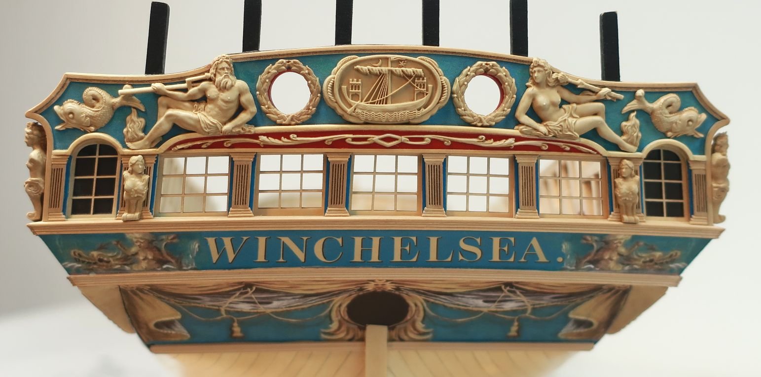
Chuck reacted to James G in HMS Winchelsea by James G (Jim) - 1:48
The NRG Merchantman Half Hull project is now complete. Excellent tool for developing planking skills. Highly recommend! More to come on my Winnie build journey.
-
Chuck got a reaction from GrandpaPhil in Sloop Speedwell 1752 by Chuck - Ketch Rigged Sloop - POF - prototype build
CHAPTER 5...Continuing with the lower platforms...there are two aft platforms. They are framed exactly like the two forward ones. Mark out the heights for the frames etc. I wont go through the step by step and instead just mention the a couple of noteworthy things.
There is another jig that helps with finding the height and position of the first beam on the upper platform. Dont throw it away after using it. It will come in handy later. Note that the mizzen mast partner is laser cut for you. Its a little longer on the forward and aft sides so you can adjust its position over the mast step to match the plans.
Just as with the forward platforms...use the plans as templates to help fins the proper positions of those ledges for the scuttle openings as well. Using them as templates helps so much and really help you see the final product.
Now that the framing is done, the next stage is to plank the lowest platform. Once again the templates of these really helps. Everything is laid out on them. Note how the deck planking hangs over the forward beam. The planks also run over the aft beam as well. Use the string to keep everything lined up down the center.
It was hard to keep everything focused in this last picture because the camera wanted to only focus on the string....but here I have attempted to show the templates positioned down the center line. They fit perfectly. I will be back with more pics after the planking is done and I start to cut some beams on that after-most platform for the stairs...
Its just busy work for a while getting the planking done. You should keep these templates because it will make life very easy when it comes to laying out all those cabins later in the project.
-
Chuck got a reaction from FrankWouts in Sloop Speedwell 1752 by Chuck - Ketch Rigged Sloop - POF - prototype build
To finish up chapter 4 and the forward platforms, the breasthooks were made. There are two of them. These are laser cut for you in two halves. Its just easier to work with them this way. I usually shape one half and lightly tack it in position. Then I shape the other half and fit it in next to it. At this point they can both be removed and joined together. Do a quick sanding to refine everything and add the bolts. The bolts are 30 lb. black line.
The lower breast hook has etched bevel lines because the side that fits against the frames needs to be beveled. Its just a start because everyone's model will be slightly different.
Lastly..to finish off this chapter I made the riding bitts. Like the fire hearth, this wont be glued in position yet. But its good to have at the ready. We will need it before framing out the rest of the forecastle deck later. So the cross beam is laser cut for you. Just clean it up and shape to suit. I just used some needle files, etc. The uprights are basically made from 5/16" x 5/16" strips. Measure against the plans and shape the tops to suit. Use the plans as a guide. Nothing earth shattering with these.
I will paint the riding bitts red above the gun deck. I used the plans to determine where that break would be. Here is what it looks like after being painted and test fit. Note the string...this is good to get in place now too. Its glued lightly to the center of the stem and then taped to the top of the stern post. It will help guide you when setting fittings along the center line. It helps a lot!!!
The fire hearth and riding bitts have been set aside for safe keeping.
Next up chapter 5 which will take care of the aft lower platforms and a few other odds and ends.
-
 Chuck got a reaction from marsalv in Sloop Speedwell 1752 by Chuck - Ketch Rigged Sloop - POF - prototype build
CHAPTER 5...Continuing with the lower platforms...there are two aft platforms. They are framed exactly like the two forward ones. Mark out the heights for the frames etc. I wont go through the step by step and instead just mention the a couple of noteworthy things.
There is another jig that helps with finding the height and position of the first beam on the upper platform. Dont throw it away after using it. It will come in handy later. Note that the mizzen mast partner is laser cut for you. Its a little longer on the forward and aft sides so you can adjust its position over the mast step to match the plans.
Just as with the forward platforms...use the plans as templates to help fins the proper positions of those ledges for the scuttle openings as well. Using them as templates helps so much and really help you see the final product.
Now that the framing is done, the next stage is to plank the lowest platform. Once again the templates of these really helps. Everything is laid out on them. Note how the deck planking hangs over the forward beam. The planks also run over the aft beam as well. Use the string to keep everything lined up down the center.
It was hard to keep everything focused in this last picture because the camera wanted to only focus on the string....but here I have attempted to show the templates positioned down the center line. They fit perfectly. I will be back with more pics after the planking is done and I start to cut some beams on that after-most platform for the stairs...
Its just busy work for a while getting the planking done. You should keep these templates because it will make life very easy when it comes to laying out all those cabins later in the project.
-
Chuck got a reaction from FrankWouts in Sloop Speedwell 1752 by Chuck - Ketch Rigged Sloop - POF - prototype build
CHAPTER 5...Continuing with the lower platforms...there are two aft platforms. They are framed exactly like the two forward ones. Mark out the heights for the frames etc. I wont go through the step by step and instead just mention the a couple of noteworthy things.
There is another jig that helps with finding the height and position of the first beam on the upper platform. Dont throw it away after using it. It will come in handy later. Note that the mizzen mast partner is laser cut for you. Its a little longer on the forward and aft sides so you can adjust its position over the mast step to match the plans.
Just as with the forward platforms...use the plans as templates to help fins the proper positions of those ledges for the scuttle openings as well. Using them as templates helps so much and really help you see the final product.
Now that the framing is done, the next stage is to plank the lowest platform. Once again the templates of these really helps. Everything is laid out on them. Note how the deck planking hangs over the forward beam. The planks also run over the aft beam as well. Use the string to keep everything lined up down the center.
It was hard to keep everything focused in this last picture because the camera wanted to only focus on the string....but here I have attempted to show the templates positioned down the center line. They fit perfectly. I will be back with more pics after the planking is done and I start to cut some beams on that after-most platform for the stairs...
Its just busy work for a while getting the planking done. You should keep these templates because it will make life very easy when it comes to laying out all those cabins later in the project.
-
Chuck got a reaction from Hubac's Historian in Sloop Speedwell 1752 by Chuck - Ketch Rigged Sloop - POF - prototype build
CHAPTER 5...Continuing with the lower platforms...there are two aft platforms. They are framed exactly like the two forward ones. Mark out the heights for the frames etc. I wont go through the step by step and instead just mention the a couple of noteworthy things.
There is another jig that helps with finding the height and position of the first beam on the upper platform. Dont throw it away after using it. It will come in handy later. Note that the mizzen mast partner is laser cut for you. Its a little longer on the forward and aft sides so you can adjust its position over the mast step to match the plans.
Just as with the forward platforms...use the plans as templates to help fins the proper positions of those ledges for the scuttle openings as well. Using them as templates helps so much and really help you see the final product.
Now that the framing is done, the next stage is to plank the lowest platform. Once again the templates of these really helps. Everything is laid out on them. Note how the deck planking hangs over the forward beam. The planks also run over the aft beam as well. Use the string to keep everything lined up down the center.
It was hard to keep everything focused in this last picture because the camera wanted to only focus on the string....but here I have attempted to show the templates positioned down the center line. They fit perfectly. I will be back with more pics after the planking is done and I start to cut some beams on that after-most platform for the stairs...
Its just busy work for a while getting the planking done. You should keep these templates because it will make life very easy when it comes to laying out all those cabins later in the project.
-
 Chuck got a reaction from Trussben in Sloop Speedwell 1752 by Chuck - Ketch Rigged Sloop - POF - prototype build
CHAPTER 5...Continuing with the lower platforms...there are two aft platforms. They are framed exactly like the two forward ones. Mark out the heights for the frames etc. I wont go through the step by step and instead just mention the a couple of noteworthy things.
There is another jig that helps with finding the height and position of the first beam on the upper platform. Dont throw it away after using it. It will come in handy later. Note that the mizzen mast partner is laser cut for you. Its a little longer on the forward and aft sides so you can adjust its position over the mast step to match the plans.
Just as with the forward platforms...use the plans as templates to help fins the proper positions of those ledges for the scuttle openings as well. Using them as templates helps so much and really help you see the final product.
Now that the framing is done, the next stage is to plank the lowest platform. Once again the templates of these really helps. Everything is laid out on them. Note how the deck planking hangs over the forward beam. The planks also run over the aft beam as well. Use the string to keep everything lined up down the center.
It was hard to keep everything focused in this last picture because the camera wanted to only focus on the string....but here I have attempted to show the templates positioned down the center line. They fit perfectly. I will be back with more pics after the planking is done and I start to cut some beams on that after-most platform for the stairs...
Its just busy work for a while getting the planking done. You should keep these templates because it will make life very easy when it comes to laying out all those cabins later in the project.
-
Chuck reacted to KennyH78 in Sloop Speedwell 1752 by Chuck - Ketch Rigged Sloop - POF - prototype build
Perfection as always, Chuck! She is going to be a stunning model when completed.
-
 Chuck got a reaction from Seventynet in Sloop Speedwell 1752 by Chuck - Ketch Rigged Sloop - POF - prototype build
CHAPTER 5...Continuing with the lower platforms...there are two aft platforms. They are framed exactly like the two forward ones. Mark out the heights for the frames etc. I wont go through the step by step and instead just mention the a couple of noteworthy things.
There is another jig that helps with finding the height and position of the first beam on the upper platform. Dont throw it away after using it. It will come in handy later. Note that the mizzen mast partner is laser cut for you. Its a little longer on the forward and aft sides so you can adjust its position over the mast step to match the plans.
Just as with the forward platforms...use the plans as templates to help fins the proper positions of those ledges for the scuttle openings as well. Using them as templates helps so much and really help you see the final product.
Now that the framing is done, the next stage is to plank the lowest platform. Once again the templates of these really helps. Everything is laid out on them. Note how the deck planking hangs over the forward beam. The planks also run over the aft beam as well. Use the string to keep everything lined up down the center.
It was hard to keep everything focused in this last picture because the camera wanted to only focus on the string....but here I have attempted to show the templates positioned down the center line. They fit perfectly. I will be back with more pics after the planking is done and I start to cut some beams on that after-most platform for the stairs...
Its just busy work for a while getting the planking done. You should keep these templates because it will make life very easy when it comes to laying out all those cabins later in the project.
-
 Chuck got a reaction from Tossedman in Sloop Speedwell 1752 by Chuck - Ketch Rigged Sloop - POF - prototype build
CHAPTER 5...Continuing with the lower platforms...there are two aft platforms. They are framed exactly like the two forward ones. Mark out the heights for the frames etc. I wont go through the step by step and instead just mention the a couple of noteworthy things.
There is another jig that helps with finding the height and position of the first beam on the upper platform. Dont throw it away after using it. It will come in handy later. Note that the mizzen mast partner is laser cut for you. Its a little longer on the forward and aft sides so you can adjust its position over the mast step to match the plans.
Just as with the forward platforms...use the plans as templates to help fins the proper positions of those ledges for the scuttle openings as well. Using them as templates helps so much and really help you see the final product.
Now that the framing is done, the next stage is to plank the lowest platform. Once again the templates of these really helps. Everything is laid out on them. Note how the deck planking hangs over the forward beam. The planks also run over the aft beam as well. Use the string to keep everything lined up down the center.
It was hard to keep everything focused in this last picture because the camera wanted to only focus on the string....but here I have attempted to show the templates positioned down the center line. They fit perfectly. I will be back with more pics after the planking is done and I start to cut some beams on that after-most platform for the stairs...
Its just busy work for a while getting the planking done. You should keep these templates because it will make life very easy when it comes to laying out all those cabins later in the project.
-
Chuck got a reaction from Mike Y in Sloop Speedwell 1752 by Chuck - Ketch Rigged Sloop - POF - prototype build
CHAPTER 5...Continuing with the lower platforms...there are two aft platforms. They are framed exactly like the two forward ones. Mark out the heights for the frames etc. I wont go through the step by step and instead just mention the a couple of noteworthy things.
There is another jig that helps with finding the height and position of the first beam on the upper platform. Dont throw it away after using it. It will come in handy later. Note that the mizzen mast partner is laser cut for you. Its a little longer on the forward and aft sides so you can adjust its position over the mast step to match the plans.
Just as with the forward platforms...use the plans as templates to help fins the proper positions of those ledges for the scuttle openings as well. Using them as templates helps so much and really help you see the final product.
Now that the framing is done, the next stage is to plank the lowest platform. Once again the templates of these really helps. Everything is laid out on them. Note how the deck planking hangs over the forward beam. The planks also run over the aft beam as well. Use the string to keep everything lined up down the center.
It was hard to keep everything focused in this last picture because the camera wanted to only focus on the string....but here I have attempted to show the templates positioned down the center line. They fit perfectly. I will be back with more pics after the planking is done and I start to cut some beams on that after-most platform for the stairs...
Its just busy work for a while getting the planking done. You should keep these templates because it will make life very easy when it comes to laying out all those cabins later in the project.
-
 Chuck got a reaction from fake johnbull in Sloop Speedwell 1752 by Chuck - Ketch Rigged Sloop - POF - prototype build
CHAPTER 5...Continuing with the lower platforms...there are two aft platforms. They are framed exactly like the two forward ones. Mark out the heights for the frames etc. I wont go through the step by step and instead just mention the a couple of noteworthy things.
There is another jig that helps with finding the height and position of the first beam on the upper platform. Dont throw it away after using it. It will come in handy later. Note that the mizzen mast partner is laser cut for you. Its a little longer on the forward and aft sides so you can adjust its position over the mast step to match the plans.
Just as with the forward platforms...use the plans as templates to help fins the proper positions of those ledges for the scuttle openings as well. Using them as templates helps so much and really help you see the final product.
Now that the framing is done, the next stage is to plank the lowest platform. Once again the templates of these really helps. Everything is laid out on them. Note how the deck planking hangs over the forward beam. The planks also run over the aft beam as well. Use the string to keep everything lined up down the center.
It was hard to keep everything focused in this last picture because the camera wanted to only focus on the string....but here I have attempted to show the templates positioned down the center line. They fit perfectly. I will be back with more pics after the planking is done and I start to cut some beams on that after-most platform for the stairs...
Its just busy work for a while getting the planking done. You should keep these templates because it will make life very easy when it comes to laying out all those cabins later in the project.
-
 Chuck got a reaction from yvesvidal in Sloop Speedwell 1752 by Chuck - Ketch Rigged Sloop - POF - prototype build
CHAPTER 5...Continuing with the lower platforms...there are two aft platforms. They are framed exactly like the two forward ones. Mark out the heights for the frames etc. I wont go through the step by step and instead just mention the a couple of noteworthy things.
There is another jig that helps with finding the height and position of the first beam on the upper platform. Dont throw it away after using it. It will come in handy later. Note that the mizzen mast partner is laser cut for you. Its a little longer on the forward and aft sides so you can adjust its position over the mast step to match the plans.
Just as with the forward platforms...use the plans as templates to help fins the proper positions of those ledges for the scuttle openings as well. Using them as templates helps so much and really help you see the final product.
Now that the framing is done, the next stage is to plank the lowest platform. Once again the templates of these really helps. Everything is laid out on them. Note how the deck planking hangs over the forward beam. The planks also run over the aft beam as well. Use the string to keep everything lined up down the center.
It was hard to keep everything focused in this last picture because the camera wanted to only focus on the string....but here I have attempted to show the templates positioned down the center line. They fit perfectly. I will be back with more pics after the planking is done and I start to cut some beams on that after-most platform for the stairs...
Its just busy work for a while getting the planking done. You should keep these templates because it will make life very easy when it comes to laying out all those cabins later in the project.
-
 Chuck got a reaction from davyboy in Sloop Speedwell 1752 by Chuck - Ketch Rigged Sloop - POF - prototype build
CHAPTER 5...Continuing with the lower platforms...there are two aft platforms. They are framed exactly like the two forward ones. Mark out the heights for the frames etc. I wont go through the step by step and instead just mention the a couple of noteworthy things.
There is another jig that helps with finding the height and position of the first beam on the upper platform. Dont throw it away after using it. It will come in handy later. Note that the mizzen mast partner is laser cut for you. Its a little longer on the forward and aft sides so you can adjust its position over the mast step to match the plans.
Just as with the forward platforms...use the plans as templates to help fins the proper positions of those ledges for the scuttle openings as well. Using them as templates helps so much and really help you see the final product.
Now that the framing is done, the next stage is to plank the lowest platform. Once again the templates of these really helps. Everything is laid out on them. Note how the deck planking hangs over the forward beam. The planks also run over the aft beam as well. Use the string to keep everything lined up down the center.
It was hard to keep everything focused in this last picture because the camera wanted to only focus on the string....but here I have attempted to show the templates positioned down the center line. They fit perfectly. I will be back with more pics after the planking is done and I start to cut some beams on that after-most platform for the stairs...
Its just busy work for a while getting the planking done. You should keep these templates because it will make life very easy when it comes to laying out all those cabins later in the project.
-
 Chuck got a reaction from KARAVOKIRIS in Sloop Speedwell 1752 by Chuck - Ketch Rigged Sloop - POF - prototype build
CHAPTER 5...Continuing with the lower platforms...there are two aft platforms. They are framed exactly like the two forward ones. Mark out the heights for the frames etc. I wont go through the step by step and instead just mention the a couple of noteworthy things.
There is another jig that helps with finding the height and position of the first beam on the upper platform. Dont throw it away after using it. It will come in handy later. Note that the mizzen mast partner is laser cut for you. Its a little longer on the forward and aft sides so you can adjust its position over the mast step to match the plans.
Just as with the forward platforms...use the plans as templates to help fins the proper positions of those ledges for the scuttle openings as well. Using them as templates helps so much and really help you see the final product.
Now that the framing is done, the next stage is to plank the lowest platform. Once again the templates of these really helps. Everything is laid out on them. Note how the deck planking hangs over the forward beam. The planks also run over the aft beam as well. Use the string to keep everything lined up down the center.
It was hard to keep everything focused in this last picture because the camera wanted to only focus on the string....but here I have attempted to show the templates positioned down the center line. They fit perfectly. I will be back with more pics after the planking is done and I start to cut some beams on that after-most platform for the stairs...
Its just busy work for a while getting the planking done. You should keep these templates because it will make life very easy when it comes to laying out all those cabins later in the project.
-
 Chuck got a reaction from mtaylor in Sloop Speedwell 1752 by Chuck - Ketch Rigged Sloop - POF - prototype build
CHAPTER 5...Continuing with the lower platforms...there are two aft platforms. They are framed exactly like the two forward ones. Mark out the heights for the frames etc. I wont go through the step by step and instead just mention the a couple of noteworthy things.
There is another jig that helps with finding the height and position of the first beam on the upper platform. Dont throw it away after using it. It will come in handy later. Note that the mizzen mast partner is laser cut for you. Its a little longer on the forward and aft sides so you can adjust its position over the mast step to match the plans.
Just as with the forward platforms...use the plans as templates to help fins the proper positions of those ledges for the scuttle openings as well. Using them as templates helps so much and really help you see the final product.
Now that the framing is done, the next stage is to plank the lowest platform. Once again the templates of these really helps. Everything is laid out on them. Note how the deck planking hangs over the forward beam. The planks also run over the aft beam as well. Use the string to keep everything lined up down the center.
It was hard to keep everything focused in this last picture because the camera wanted to only focus on the string....but here I have attempted to show the templates positioned down the center line. They fit perfectly. I will be back with more pics after the planking is done and I start to cut some beams on that after-most platform for the stairs...
Its just busy work for a while getting the planking done. You should keep these templates because it will make life very easy when it comes to laying out all those cabins later in the project.