
Chuck
-
Posts
9,390 -
Joined
-
Last visited
Reputation Activity
-

.jpg.d84ec4dad1d7791e855dca06210ab6f3.thumb.jpg.f45209242e851d4409eca1a09293165b.jpg) Chuck got a reaction from hollowneck in Syren Ship Model Company News, Updates and Info.....(part 2)
Chuck got a reaction from hollowneck in Syren Ship Model Company News, Updates and Info.....(part 2)
Oh and two more things...
I spoke too soon.
I cracked the code...1:64 or 3/16" scale belaying pins are now in stock. They are 7.4 mm long or 9/32".
In addition...the first batch of chapter 4 parts for Speedwell are also in stock. Dont worry more of these will follow.
-
 Chuck got a reaction from glbarlow in Syren Ship Model Company News, Updates and Info.....(part 2)
Oh and two more things...
I spoke too soon.
I cracked the code...1:64 or 3/16" scale belaying pins are now in stock. They are 7.4 mm long or 9/32".
In addition...the first batch of chapter 4 parts for Speedwell are also in stock. Dont worry more of these will follow.
-
 Chuck got a reaction from Canute in Syren Ship Model Company News, Updates and Info.....(part 2)
Oh and two more things...
I spoke too soon.
I cracked the code...1:64 or 3/16" scale belaying pins are now in stock. They are 7.4 mm long or 9/32".
In addition...the first batch of chapter 4 parts for Speedwell are also in stock. Dont worry more of these will follow.
-
 Chuck got a reaction from KARAVOKIRIS in Syren Ship Model Company News, Updates and Info.....(part 2)
Extra Large stern lanterns also now available and in stock. Good for those 1/4" scale 3 deckers. They are 33mm tall without a crank.
Chuck
-
 Chuck got a reaction from Archi in Syren Ship Model Company News, Updates and Info.....(part 2)
Oh and two more things...
I spoke too soon.
I cracked the code...1:64 or 3/16" scale belaying pins are now in stock. They are 7.4 mm long or 9/32".
In addition...the first batch of chapter 4 parts for Speedwell are also in stock. Dont worry more of these will follow.
-
 Chuck got a reaction from gjdale in Syren Ship Model Company News, Updates and Info.....(part 2)
Oh and two more things...
I spoke too soon.
I cracked the code...1:64 or 3/16" scale belaying pins are now in stock. They are 7.4 mm long or 9/32".
In addition...the first batch of chapter 4 parts for Speedwell are also in stock. Dont worry more of these will follow.
-
 Chuck got a reaction from CiscoH in Syren Ship Model Company News, Updates and Info.....(part 2)
Oh and two more things...
I spoke too soon.
I cracked the code...1:64 or 3/16" scale belaying pins are now in stock. They are 7.4 mm long or 9/32".
In addition...the first batch of chapter 4 parts for Speedwell are also in stock. Dont worry more of these will follow.
-
 Chuck got a reaction from KentM in Syren Ship Model Company News, Updates and Info.....(part 2)
First 3D print test and assembly of two French style lanterns after Boudriot. There is no glazing insert in these....yet. Thats a bit more complex than the other Royal Navy shaped insert.
-
Chuck got a reaction from Archi in Syren Ship Model Company News, Updates and Info.....(part 2)
Extra Large stern lanterns also now available and in stock. Good for those 1/4" scale 3 deckers. They are 33mm tall without a crank.
Chuck
-
 Chuck got a reaction from GrandpaPhil in Syren Ship Model Company News, Updates and Info.....(part 2)
Extra Large stern lanterns also now available and in stock. Good for those 1/4" scale 3 deckers. They are 33mm tall without a crank.
Chuck
-

 Chuck got a reaction from Ryland Craze in Syren Ship Model Company News, Updates and Info.....(part 2)
Extra Large stern lanterns also now available and in stock. Good for those 1/4" scale 3 deckers. They are 33mm tall without a crank.
Chuck
-
 Chuck got a reaction from PaddyO in Syren Ship Model Company News, Updates and Info.....(part 2)
Extra Large stern lanterns also now available and in stock. Good for those 1/4" scale 3 deckers. They are 33mm tall without a crank.
Chuck
-
Chuck got a reaction from KentM in Syren Ship Model Company News, Updates and Info.....(part 2)
Extra Large stern lanterns also now available and in stock. Good for those 1/4" scale 3 deckers. They are 33mm tall without a crank.
Chuck
-
 Chuck got a reaction from thibaultron in Syren Ship Model Company News, Updates and Info.....(part 2)
Extra Large stern lanterns also now available and in stock. Good for those 1/4" scale 3 deckers. They are 33mm tall without a crank.
Chuck
-
 Chuck got a reaction from druxey in Syren Ship Model Company News, Updates and Info.....(part 2)
Extra Large stern lanterns also now available and in stock. Good for those 1/4" scale 3 deckers. They are 33mm tall without a crank.
Chuck
-
Chuck got a reaction from Canute in Syren Ship Model Company News, Updates and Info.....(part 2)
Extra Large stern lanterns also now available and in stock. Good for those 1/4" scale 3 deckers. They are 33mm tall without a crank.
Chuck
-
 Chuck got a reaction from Jack12477 in Syren Ship Model Company News, Updates and Info.....(part 2)
Extra Large stern lanterns also now available and in stock. Good for those 1/4" scale 3 deckers. They are 33mm tall without a crank.
Chuck
-
 Chuck got a reaction from Ronald-V in Syren Ship Model Company News, Updates and Info.....(part 2)
Extra Large stern lanterns also now available and in stock. Good for those 1/4" scale 3 deckers. They are 33mm tall without a crank.
Chuck
-

-
 Chuck got a reaction from Jorge Diaz O in Learn how to gain access to the HMS Triton Plans
Indeed they are....Go here to sig up....then you will be given access.
https://thenrgstore.org/collections/plans-and-projects
Chuck
-
 Chuck reacted to palmerit in Ranger 1864 by palmerit - Vanguard Models - 1:64 - Barking Fish Carrier
I decided to get the Syren Servo-Matic Serving Machine. It needs to be built.
First step is sanding all the cherry wood pieces (except for the gears).
-
Chuck got a reaction from Ryland Craze in Queen Anne Royal Barge Circa 1704 by MikeB4 - Syren - 1:24
CA is fine...Its looking great.
-
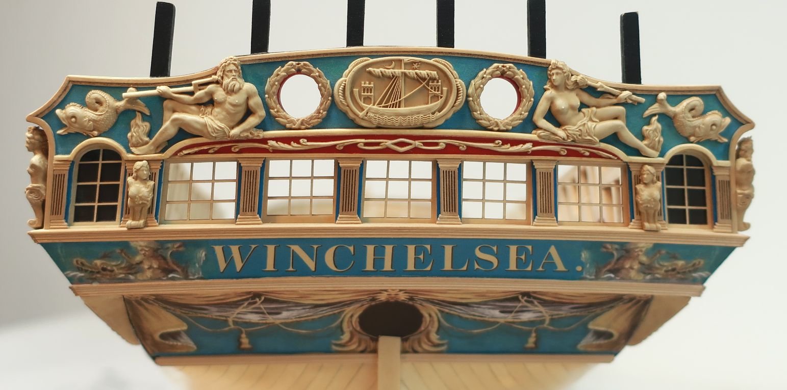
Chuck reacted to shauer in HMS Winchelsea 1764 by shauer - 1:48
Progress was a little slower than I expected this week. I got the two strakes below the Wales completed after wrestling with a drop plank and getting the planks to meet at the lower counter neatly. I didn't achieve the perfect seam I have seen on some projects but I think it will work out alright once the 1/8 inch molding is applied.
I also received my order of the next few chapters plus the resin castings. Thanks Chuck!
After my first couple attempts at getting the taper correct, I resorted to popping loose the end of the drop plank so that I had some minimal adjustment to get a tight joint both above and below the tapered plank.
I struggled with the first strake below the Wales where it joins the lower counter. I could not get a nice neat mitered joint that also lined up neatly with the corner between the lower counter and the lowest plank of the Wales. So I resorted to just letting the hull planks lap the lower counter. I figure I can hide this under the 1/8 inch wide molding that is placed along this seam. Anyone have other thoughts on this?
This is only rough sanded, it will clean up a little more with a final finish sand.
And of course I just had to get the figurehead placed on the bow to see what it looks like.
I'm working today on edge-painting the planks that will be used for the top and bottom strakes of the Wales and will start installing them this week.
Steve
-
Chuck reacted to westwood in HMS Portland 1770 by westwood - Portland Scale Ship Co. - 1:48 - 50 gun 4th rate
So, here's another update after the weekend.
A lot of sanding, and finally, keel mounting.
-
 Chuck got a reaction from MikeB4 in Queen Anne Royal Barge Circa 1704 by MikeB4 - Syren - 1:24
CA is fine...Its looking great.