


mbp521
-
Posts
989 -
Joined
-
Last visited
Content Type
Profiles
Forums
Gallery
Events
Posts posted by mbp521
-
-
Nice tutorial Keith! Thanks for the info. I think that I have tried a similar method with wire before but I always either seemed to split the blocks with too many twists or I crushed them with the pliers. That’s probably why I mostly strop them with rigging line. Of course I most likely was using too big of wire for the process. I’ll file your method away and give it another shot with a smaller gauge wire when I get around to doing some more rigging.
-Brian
-
9 hours ago, Cathead said:
I can't tell if it's a trick of the lighting, but did you add a little color on the tarps beneath the ropes? Or is that just a shadow? Because it would make sense for the ropes to leave a little staining under their run. I can only echo the others in saying how fantastic that all looks, and that I want to remember that boat tarp technique.
Thank you Eric. On my first attempt I used the pastels to show the seams in the tarp, so when I redid it, I used the same technique. What I did write not about in the post was that there was another attempt before the final one where I ran the ropes across the top of the tarp, then covered it with tissue paper to give the look of the ropes being sewn within the seams. This idea proved to be a big mistake and looked horrible. So I went with my third version and strapped the ropes across the tarp and then highlighted them with the pastels. I was going for the look of the sewn seems underneath the ropes and never thought about the rope staining the canvas. However, that is a great accidental detail you pointed out that I’ll have to use again in the future.
-Brian
- Cathead, mtaylor, Keith Black and 2 others
-
 5
5
-
17 hours ago, FriedClams said:
Wonderful exacting work Brian, as I always know it will be. The boats came out great and the canvas is very believable. Your modeling is always very complete and you never skip over the small details - like pipe hangers, or elbows on your steam piping - excellent, I love the surprise of the unexpected. Nice grey base color too. There’s just something about raw umber that adds a deep, complex look of age.
Gary
Thank you Gary. I sure wish I was a better photographer because the pictures truly do no justice to the color. I lost count as to how many coats of different grays I put on my mock-up before I finally found a color that I liked. I was struggling to get the blue out of mixing the black and white and the Raw Umber was the final addition that did the trick.
-Brian
- FriedClams, Keith Black, mtaylor and 1 other
-
4
-
Beautiful job Eric! I love the fact that you took an otherwise normal model and made it your own. Adding to the fact that you used home grown wood all milled on-site, not just for the hull but the display as well. Absolutely fantastic!
I just recently purchased the capstan project plans and will follow your build closely, as that will be my next project
-Brian
-
Hello again everyone,
I figured it was about time that I get another update out there since it has been a day or two since my last one.
I continued with work on the roof beams. I started with the area around the chimneys first, since there were so many pieces to fit together. The frames around the top of the flume were built first.
Then the frames for the funnels were built.
Once the whole section was assembled it was installed on the boat.
Next I built the hangers for the piping. These were made from 24ga wire for the hanger rods and some scrap 3/16" x 1/16" strips for the supports that I had. I used small beads to simulate the nuts on the ends of the rods and painted and stained everything up.
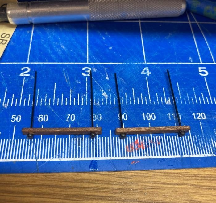
Then they were installed along the roof beams.
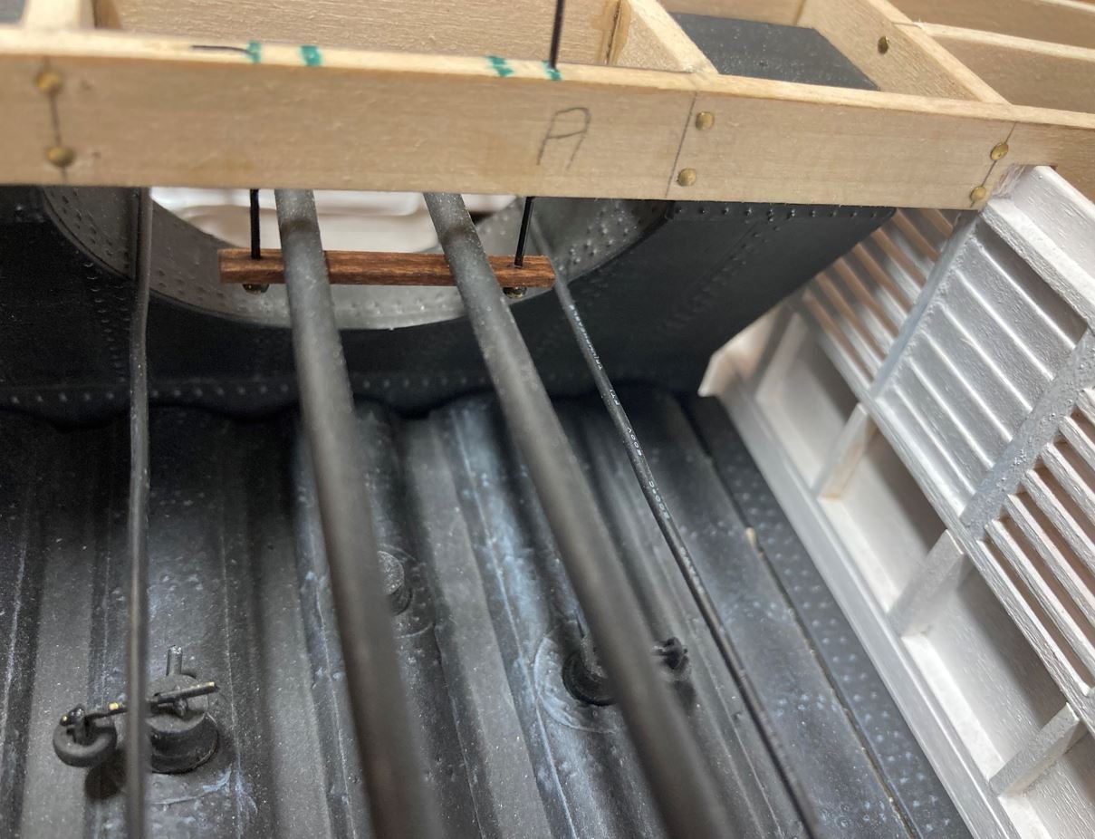
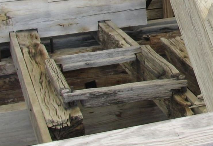
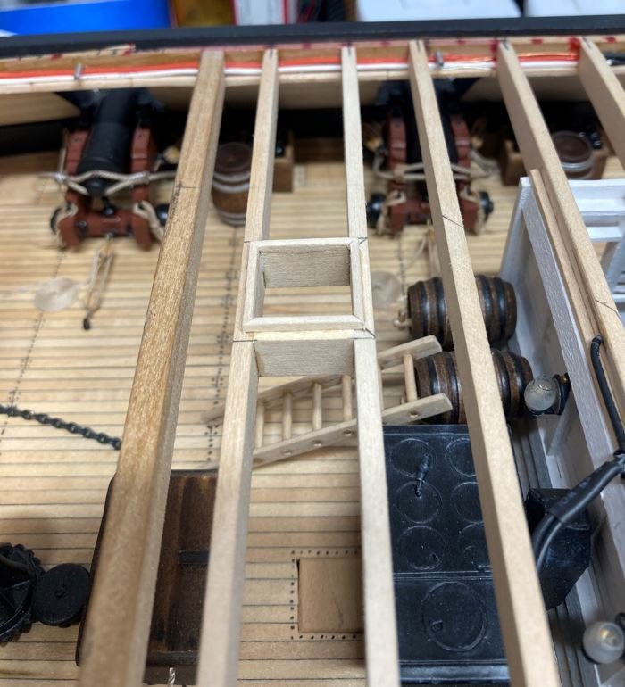
Next I moved on to the roof beams forward of the boilers. This area contained the access hatch for the pilot house. This was another area that was lost during the salvage, so I did the best that I could to truly represent the way that I though this might have been built up. The location of the hatch is shown on the HSR plans and I used one of the examples for the comings from one on the existing gun deck that survived.
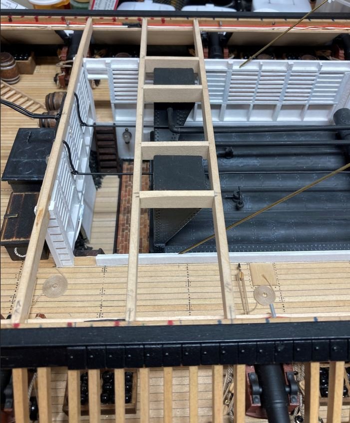
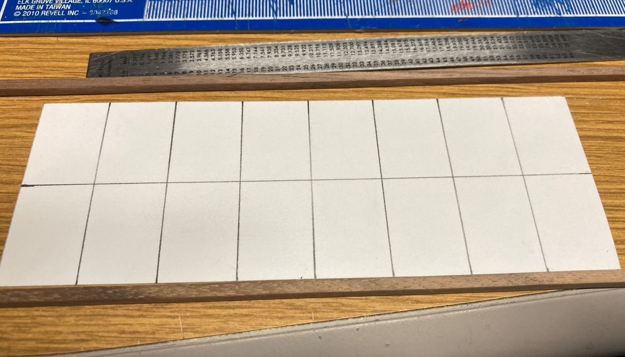
Next it was on to constructing the skylight over the boiler. This was another area that did not survive the salvage. It was crushed when the mid-section of the ship collapsed in the cables when being moved to the barge so details are going to be pretty much left up to builders liberties. So what I did was follow the HSR plans that called for framing of 16 openings covered with a mesh screen that sat above the boilers, most likely to let out the excess heat and smoke. My take on this is that the funnels that sat just forward of the chimney could be turned into the wind to direct the airflow down into the boiler hold. The forced air from the funnels would flow through the boiler room, then up and out of the skylight.
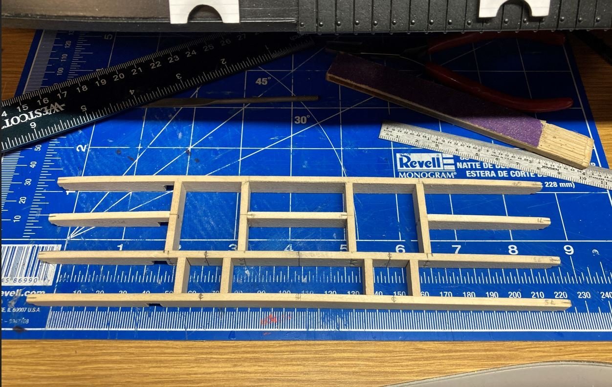
This is the template I used for the framing.
Frames constructed.
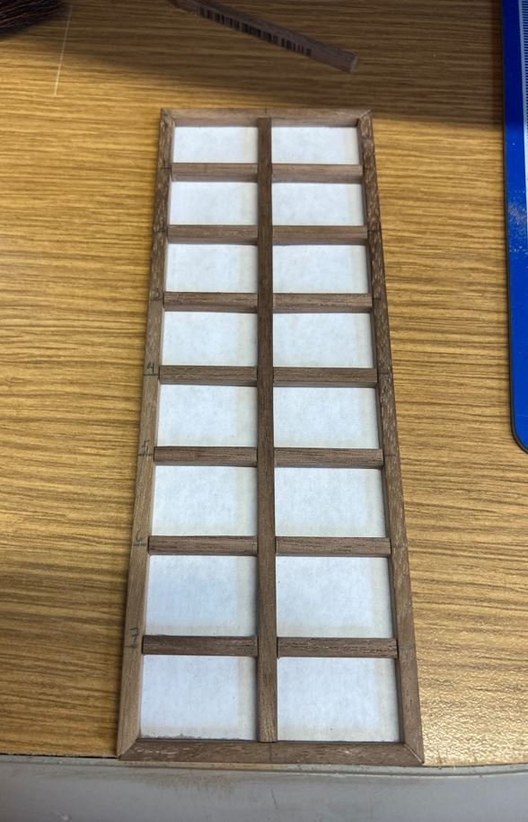
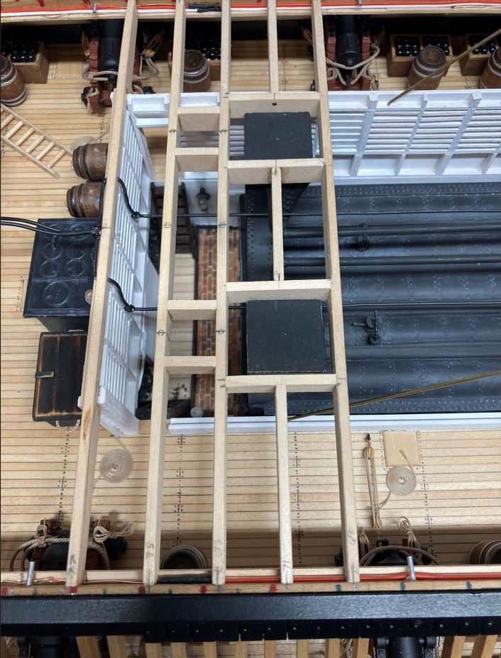
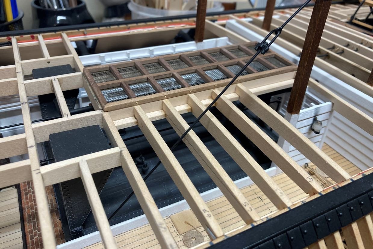
Mesh installed and then the whole assembly placed in the roof frames.
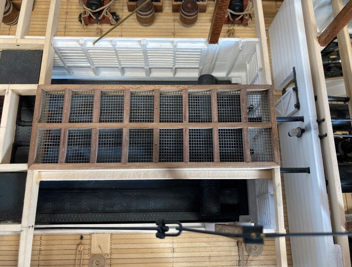
Then the remainder of the roof beams were installed.
Once I had the roof beams installed. I moved on the ships boats. These boat have taken on a life of their own and have been a very time consuming project. In one of my previous posts, I had shown that I had used the Model Shipways 5 3/16" lifeboat kits for these. Since these were the longest kits that I could find, they had to be modified and stretched to 6 3/16" to fit the proper scale of my build. I was having some difficulty trying to get the correct color schemes for these boats and I finally decided that I was going with a black hull with an off-white interior, to match the one shown in the only photo of the Cairo.
I had first started out with the plan to build all four boats covered, since there was very little detail on the boats. However the more I thought about it, the more I figured, I am going through all the trouble to try and get this build as accurate as possible, then why not show some of the detail in these boats. I then decided that I would do all of them uncovered with the interior details because I wasn't sure if I could get the look of the boat covers to look right. Finally, I went ahead and decided to go with two covered boats and two uncovered. My confidence level was not very high on simulating the tarps, but how am I ever going to learn how to do something if I don't try.
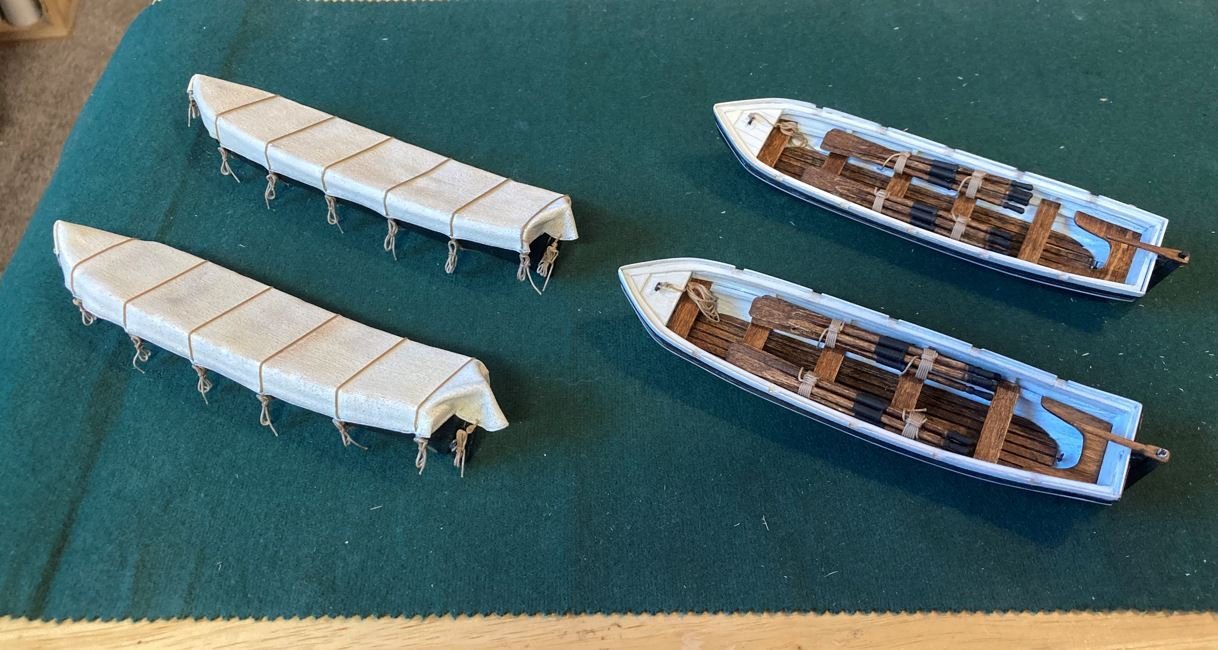
So here is my process for the boats.
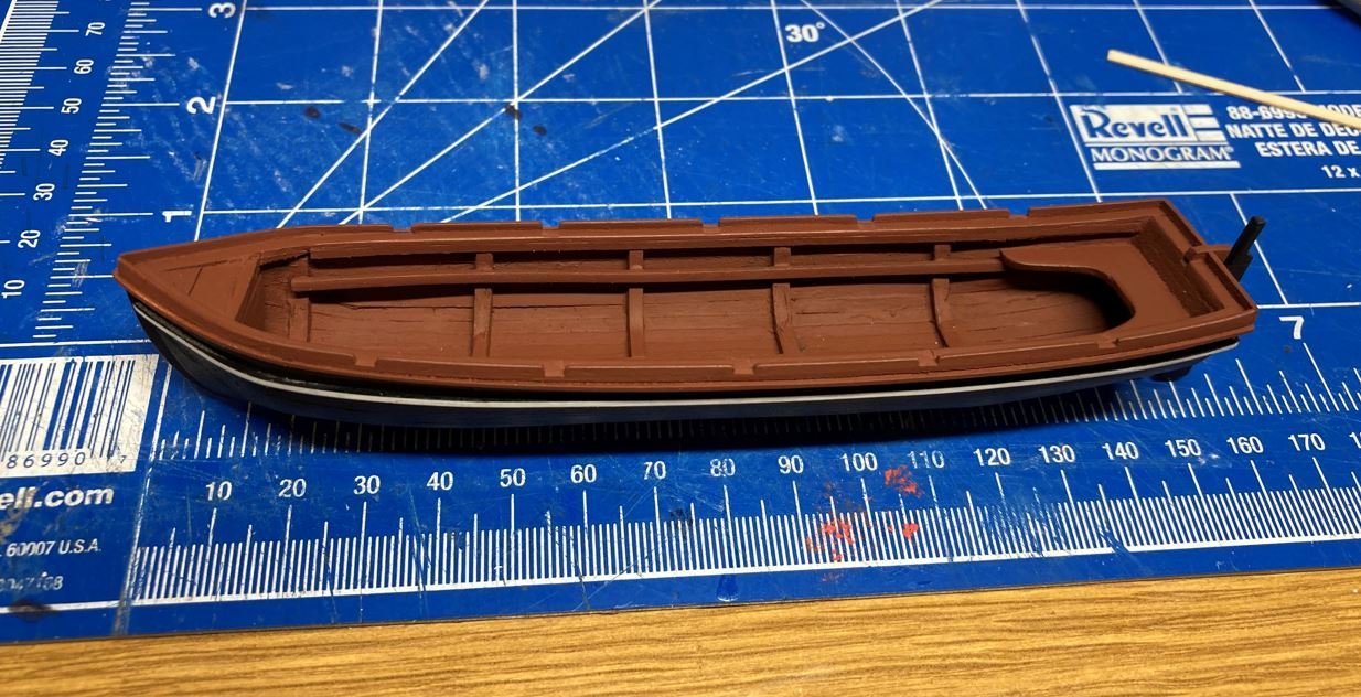
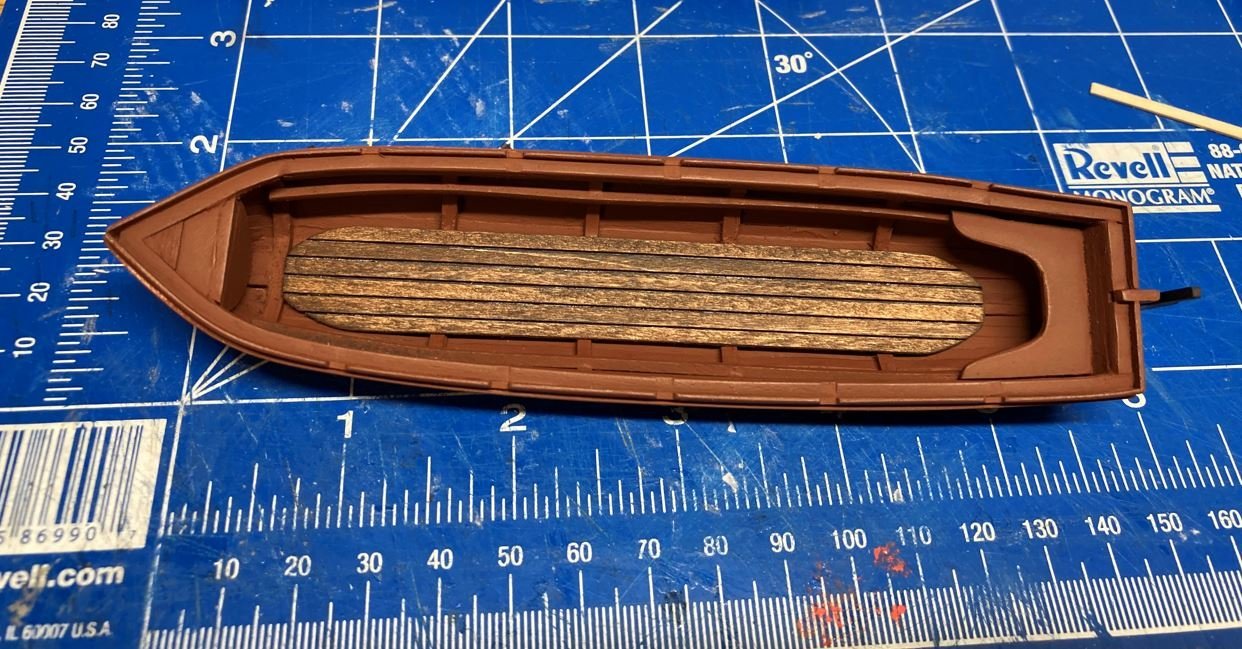
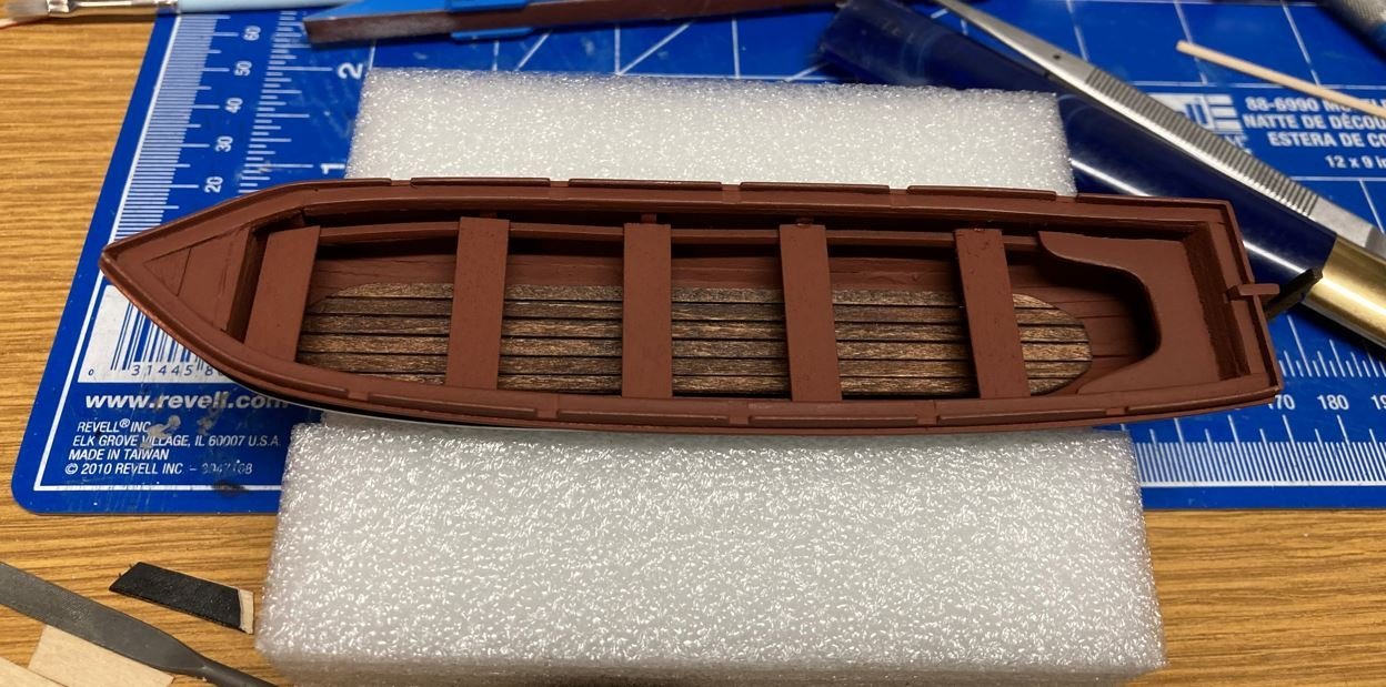
I started with the covered boats first, since I was still researching the correct colors of the interior and of the oars. The boats were initially painted with the reddish-brown color, which I later on found to be incorrect, but since I was going to cover them, I figured there was no need to go back and paint them again.
Here is the construction of the covered boats.
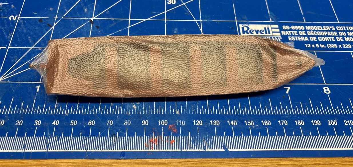
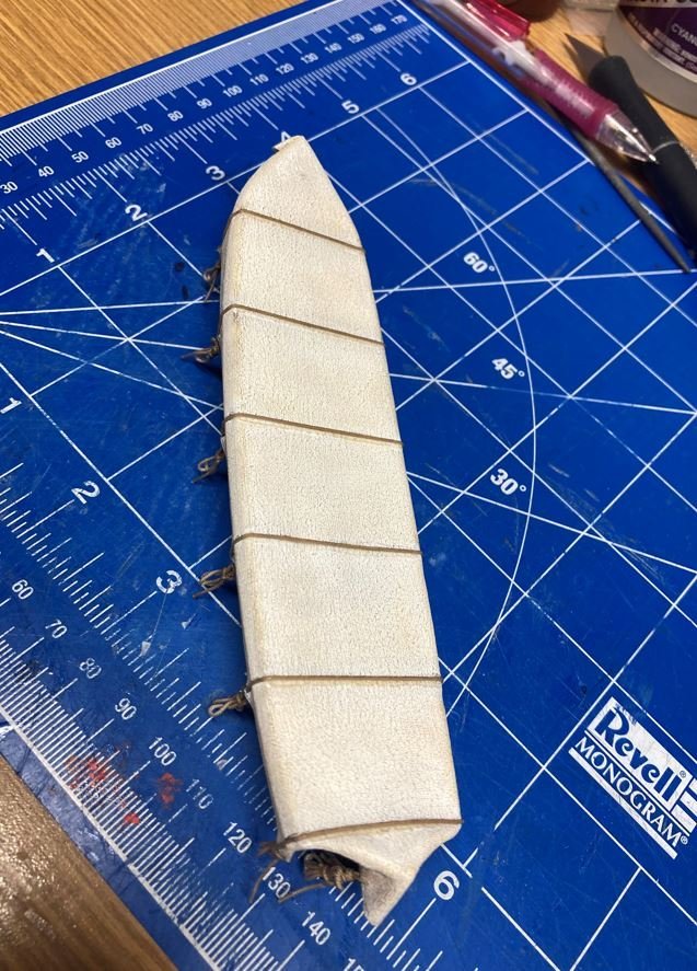
To simulate the tarps, I first wrapped the boats in some press and seal I borrowed from the Admirals kitchen (with her permission of course). This would allow me to remove the tarp once it formed to the boat.
I then took an old pillowcase and wrapped that around the boat.
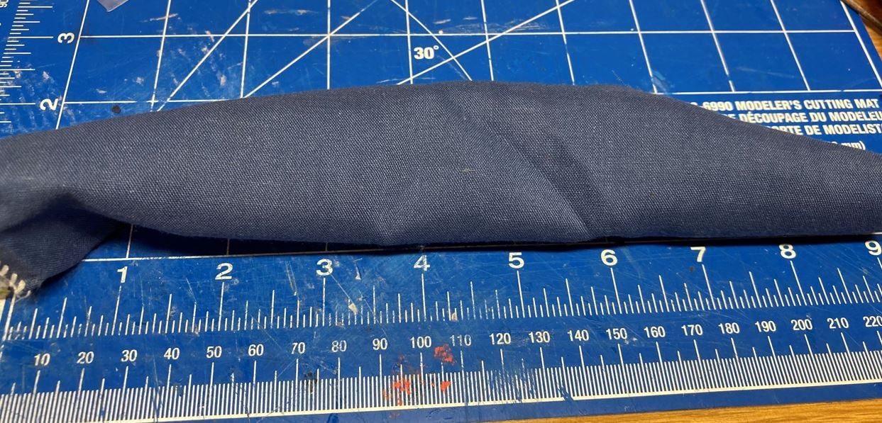
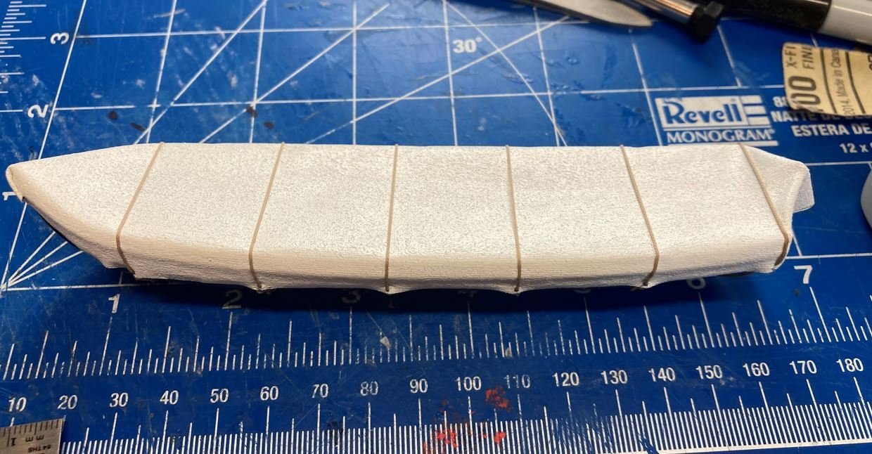
Then I applied several diluted coats of clear Elmer's glue to stiffen the fabric, then several coats of white acrylic paint.
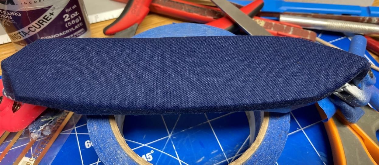
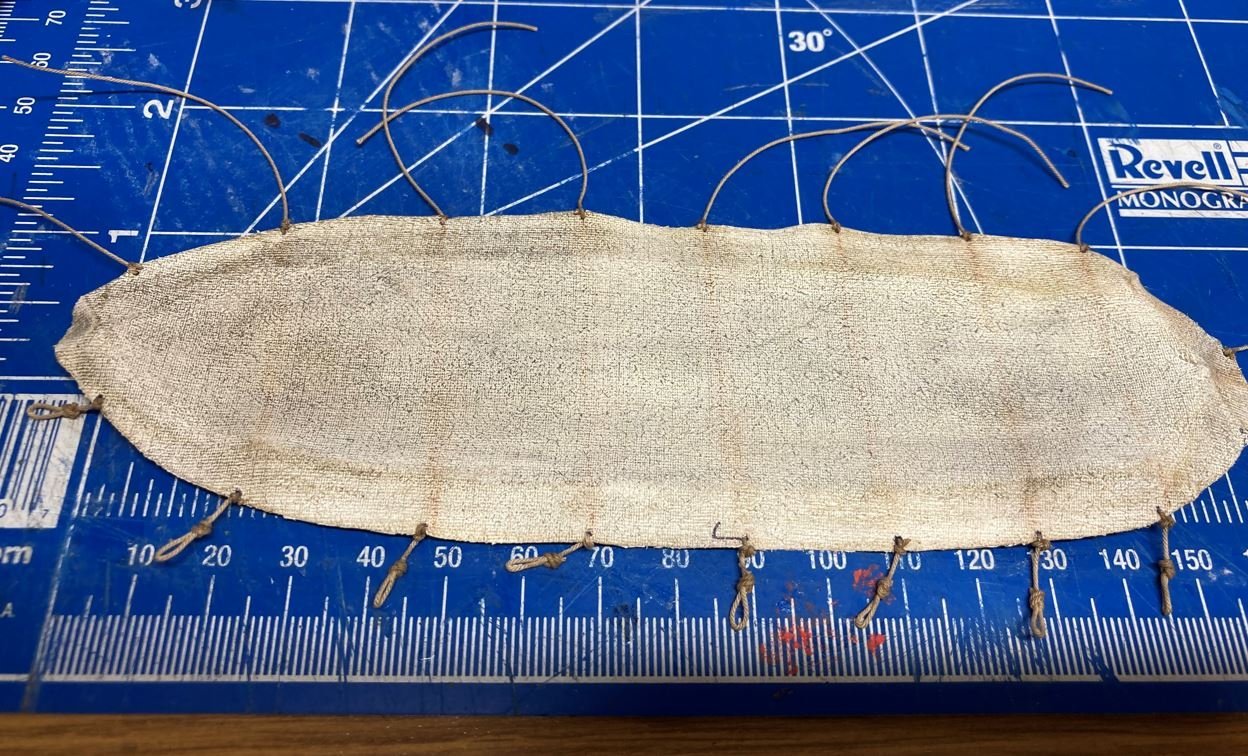
Once the pain had dried, I removed the tarp from the boat, flattened it out and started installing the tie-down ropes. I also added some weathering to give a little bit of an aged look.
Back on the boat, I started securing the ropes and fitting the tarp back into place.
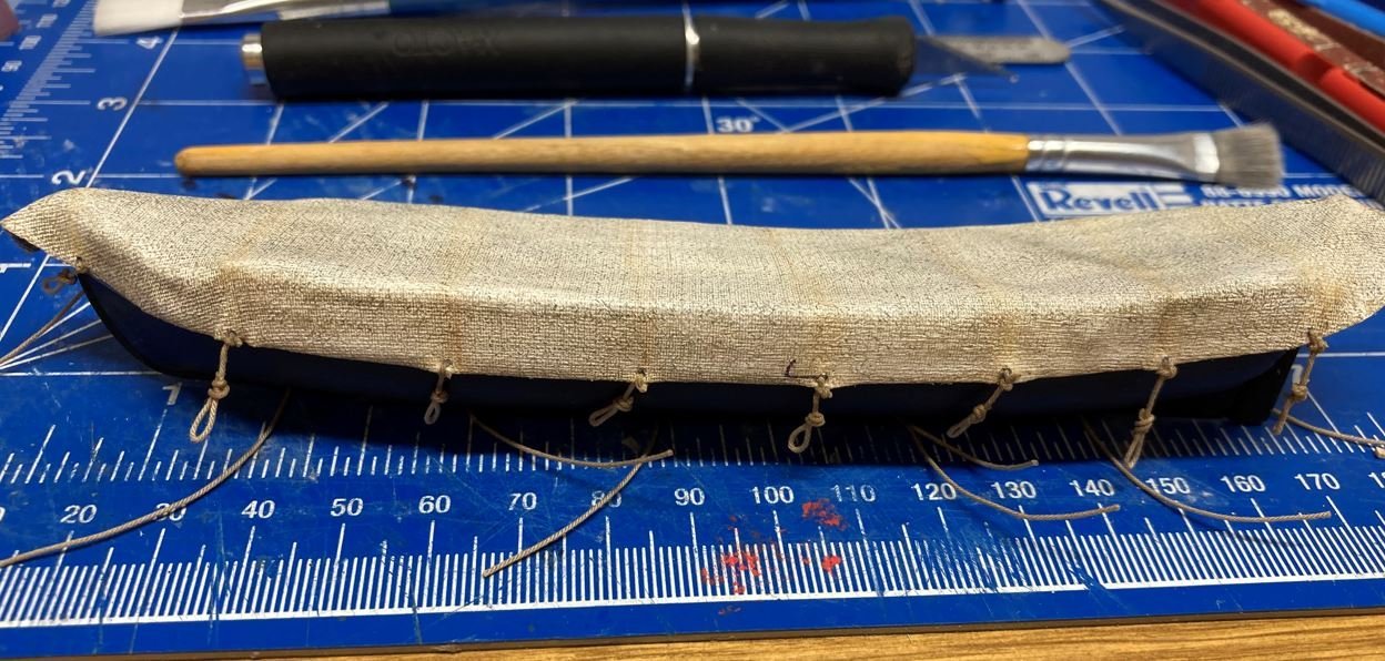
It was at this point, that I found that I was not happy with the way this was looking. Something seemed to be missing. When I was weathering the tarp, I tried simulating the seams of the canvas that would have been sewn together the make the cover and thought that this needed more. So I went back and tried it again.
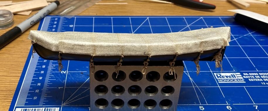
Following the same procedure as before, this time I decided that the ropes needed to go completely around the boat.
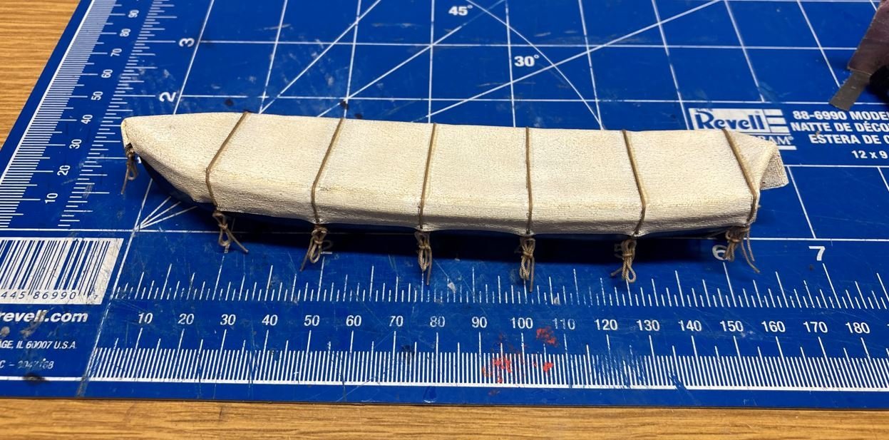
This seemed to add a more realistic look to the way the covers fell over the sides of the boats and provided some separation of the cover sections.
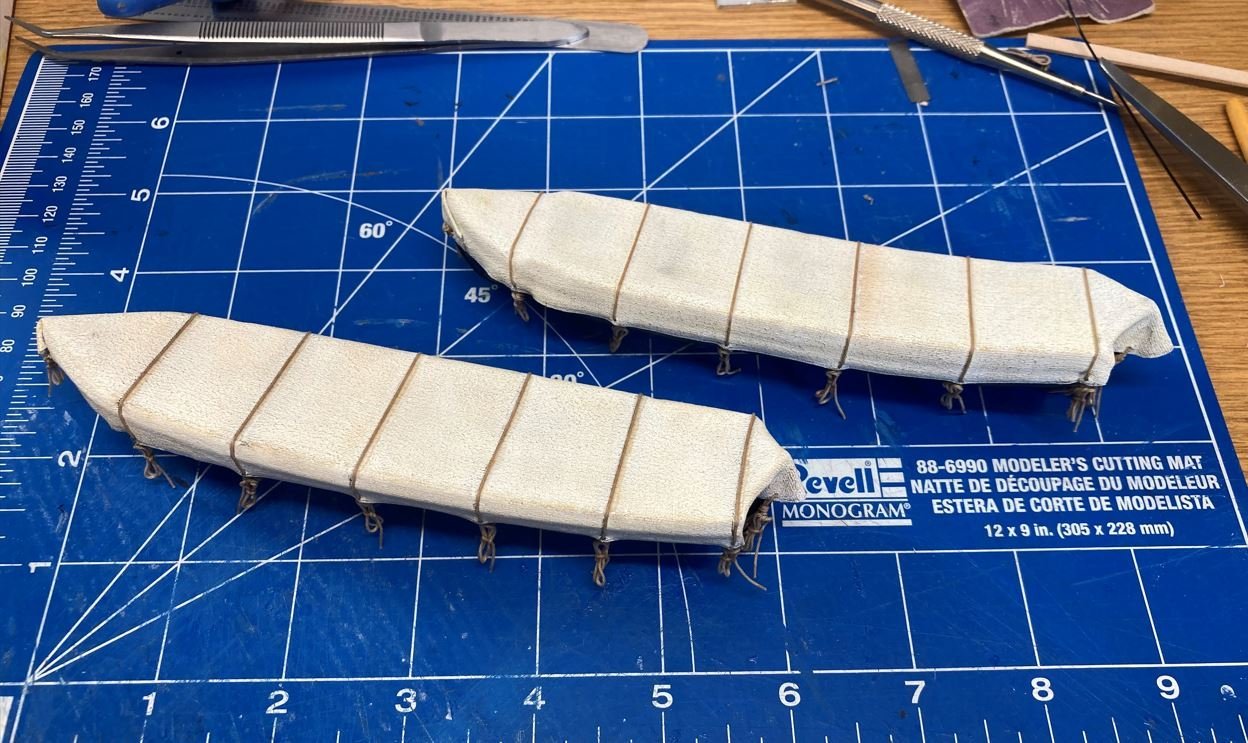
So I tossed the original one and built two this way.
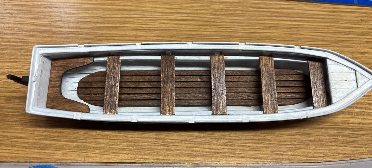
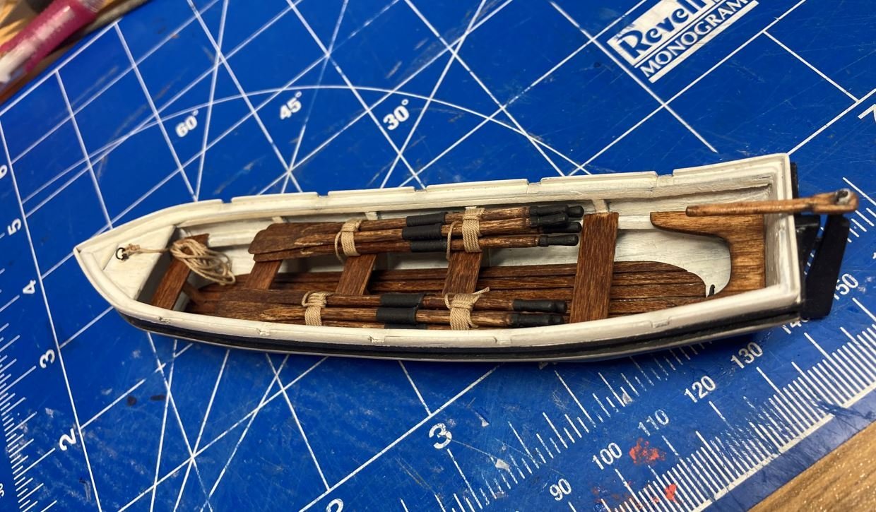
Then it was on to the open boats. I painted these with a white interior and gave them a bit of an aged, off-white look with some pastels.
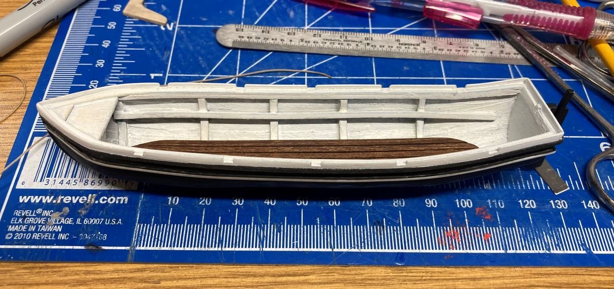
I went ahead and stained the benches, since I had already built the floorboards and stained them and I wanted them to match.
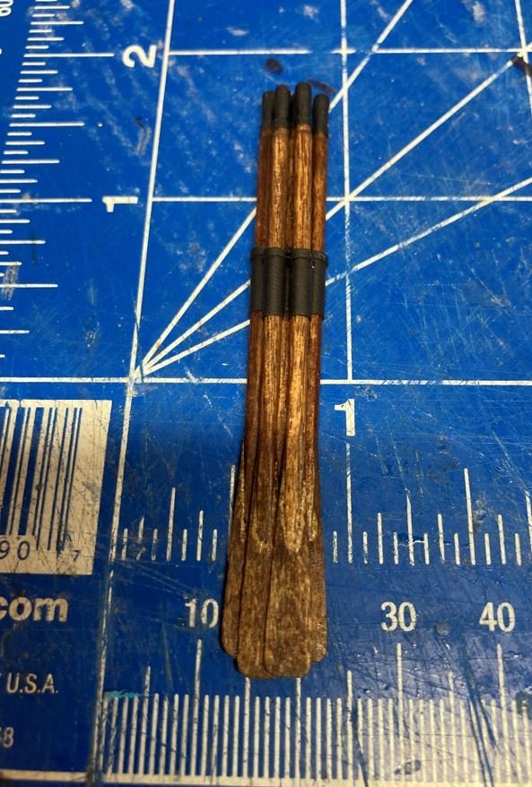
Using all of the great input from everyone, I went ahead and finished out the oars. I used the same stain as the benches and floorboards to keep the colors consistent. I then used some small heat shrink to simulate the leather sleeves that protect the oars from wear in the oarlocks.
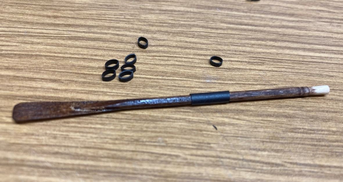
I painted the handles black, only because I liked the look of the black with the stain.
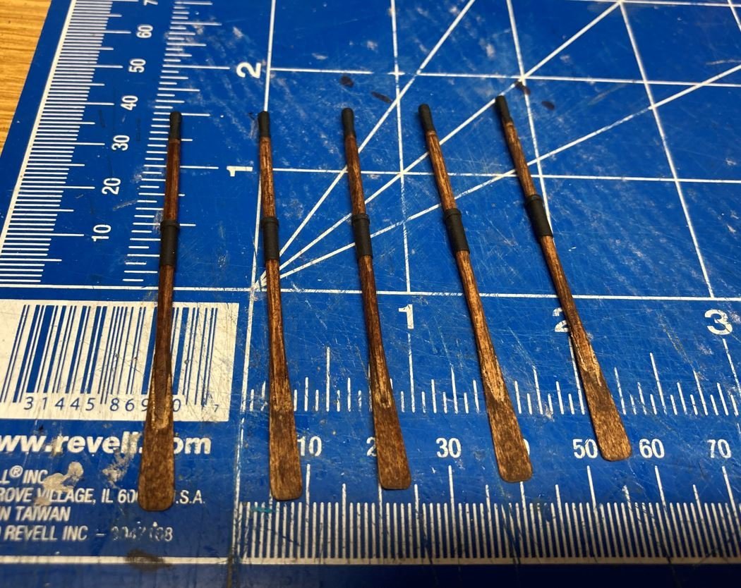
Then the oars were bundled together.
Then lashed to the insides of the boats.
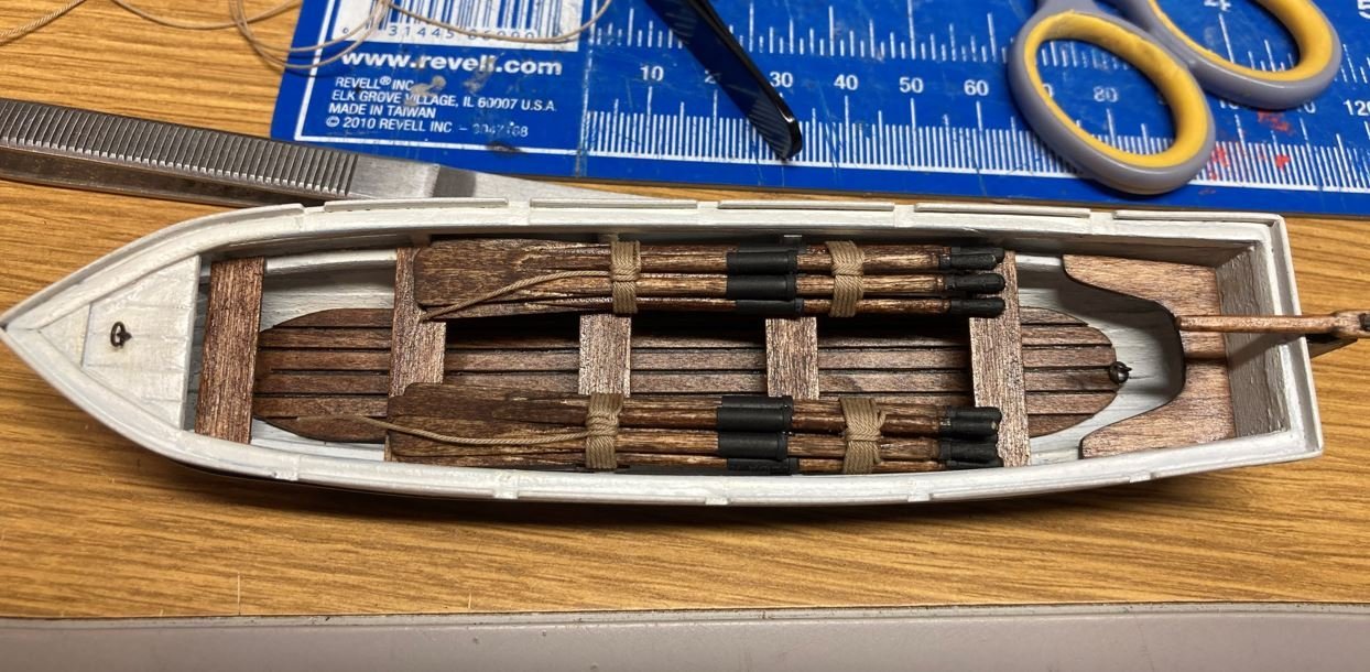
A shoring rope and tiller was added as well as some more weathering to the oarlocks.
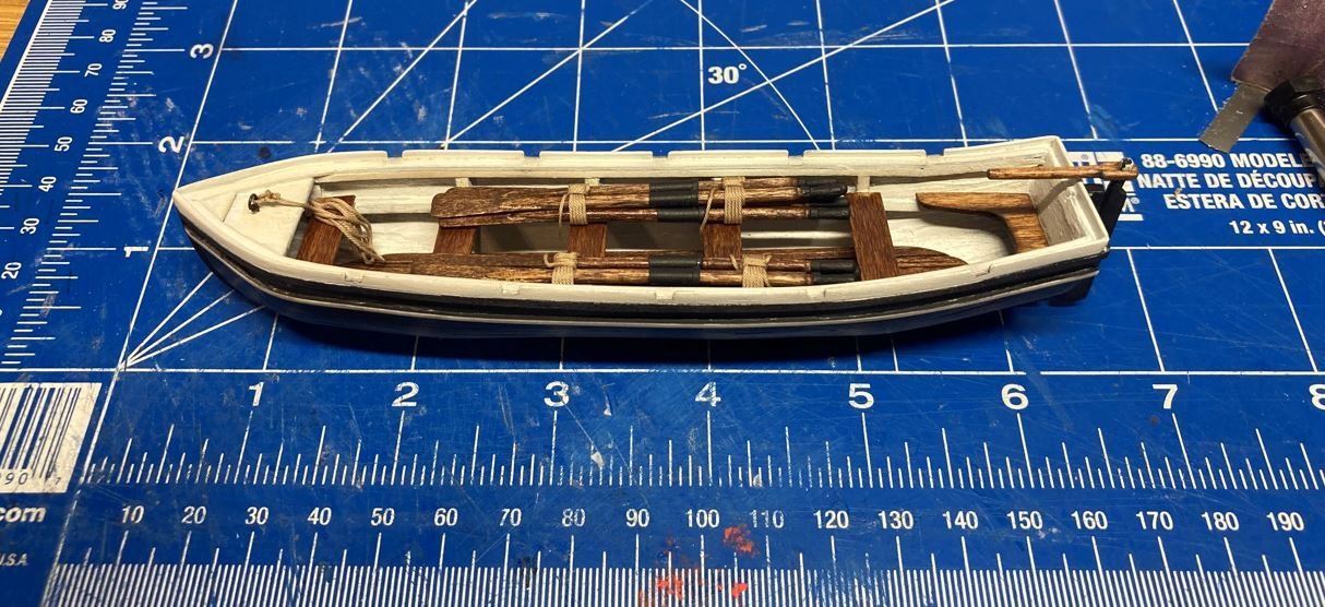
And the second uncovered boat was completed.
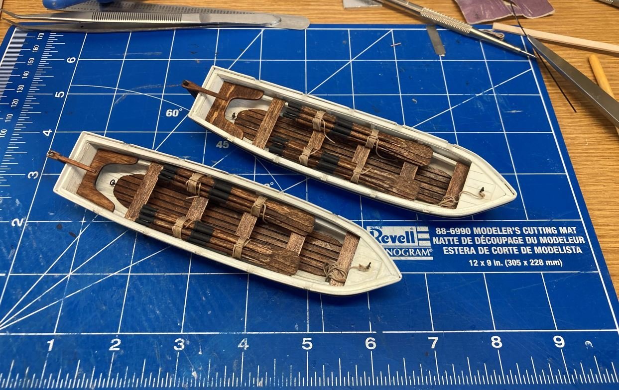
All four boats complete.
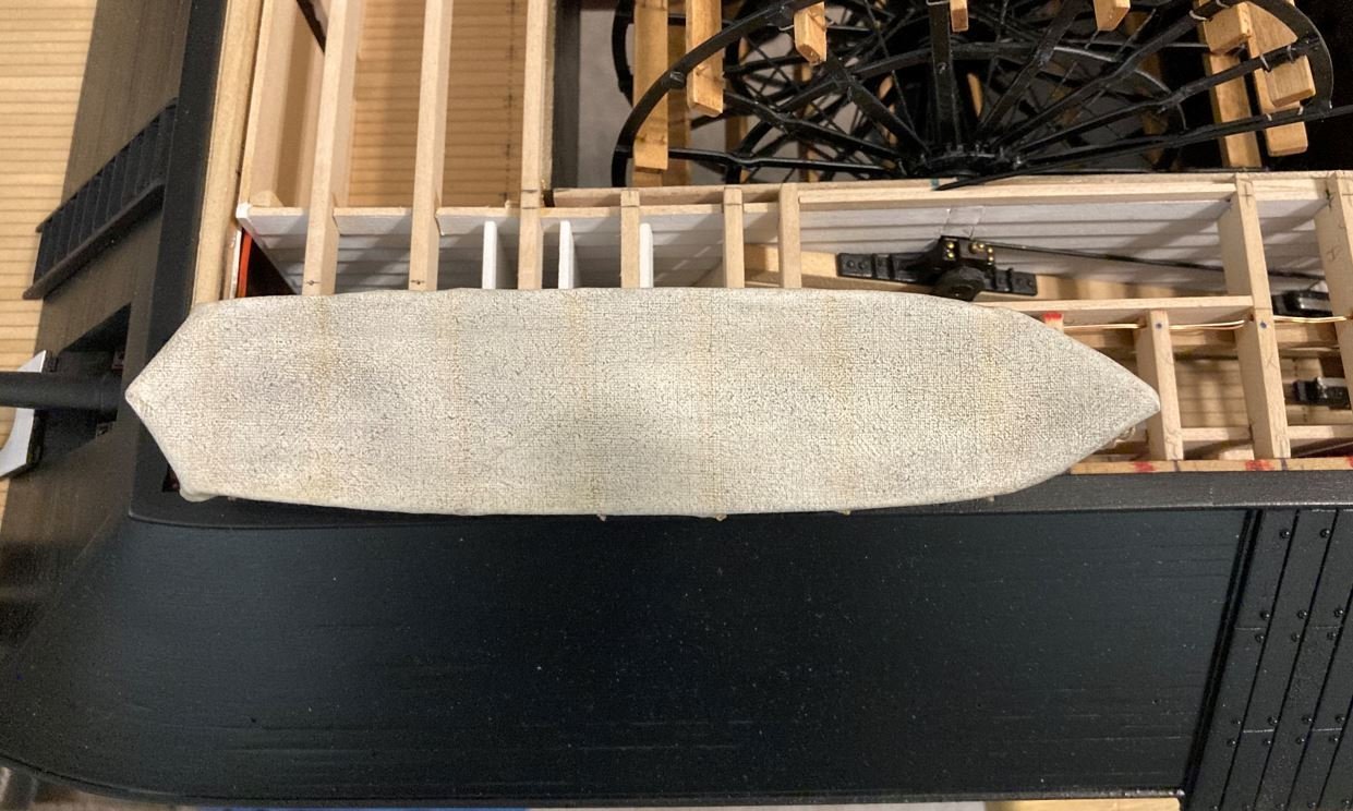
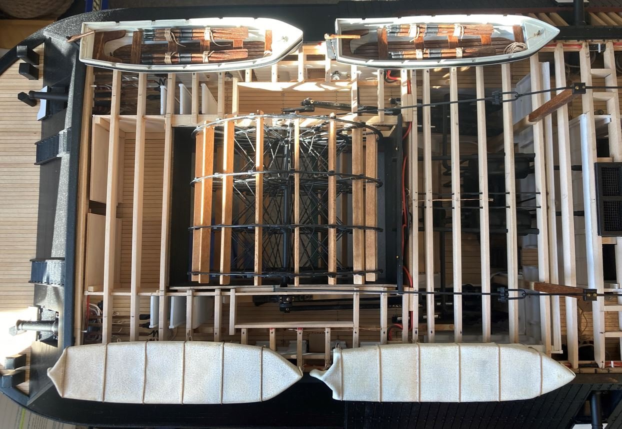
All four boats on the ship, just to give an idea of what they will look like in place. They will actually rest in the davit supports slightly outboard of the current position now. Since the forward port boat will hang over the cutaway opening, I am thinking of showing this boat as in the process of being launched and sitting at the water level but still in the rigging. This will keep the boat from blocking the view of the interior and add a little action to the build.
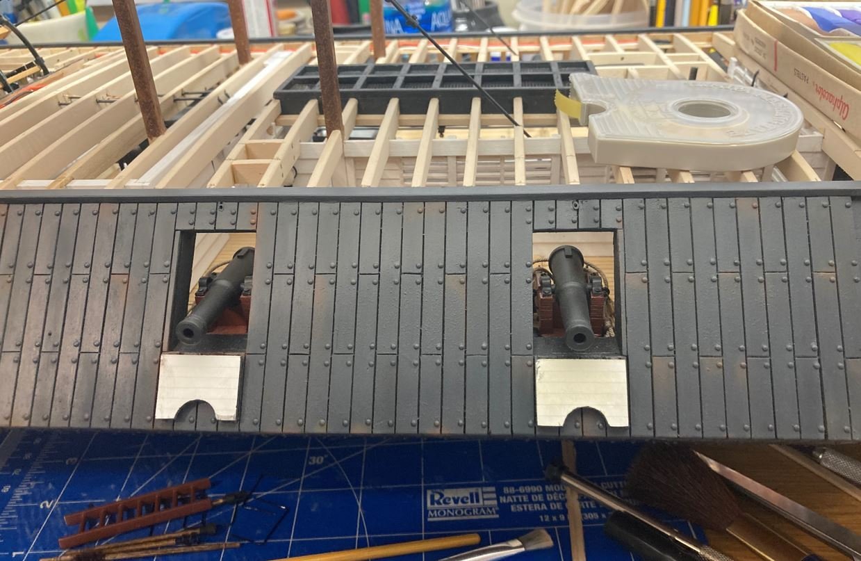
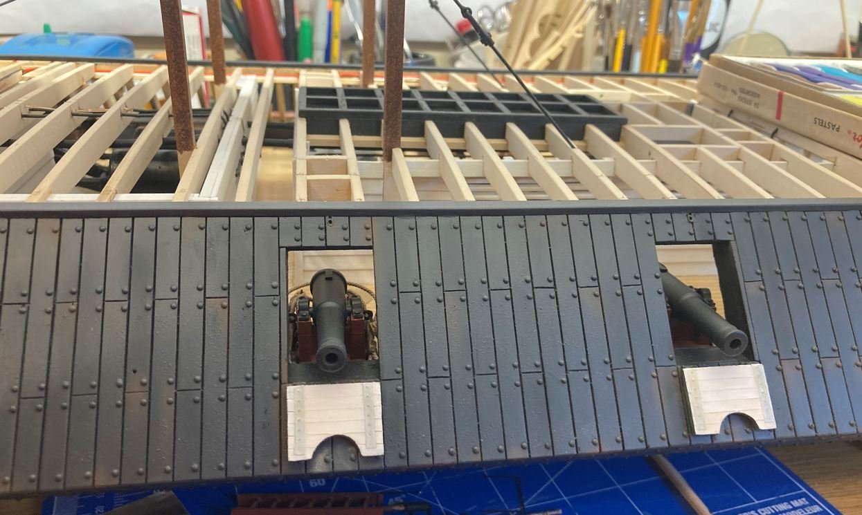
Lastly, I started playing around with the coloring and some of the weathering. I finally found a base color that I am happy with for the casemates. I mixed together black with a touch of white and raw umber. It gave me a nice looking dull gray that is not too light, yet not too dark either. I also played around with some weathering pastels, adding some rust to the railroad irons and armor plating. I also toned down the bright white of the port door interiors with pastels and added the inside straps and rivets. I cannot get the lighting right to do the pictures any justice, but from what I can see, I am liking the colors.
Well, that is all for this update. As always, thanks for stopping by and all the likes and kind comments.
-Brian
-
On 11/17/2021 at 12:20 AM, mtaylor said:
Have you come across any paintings of the ironclads? They might be a better source for figuring out colors. I think the iron plating was basicaly black cast iron.
Mark,
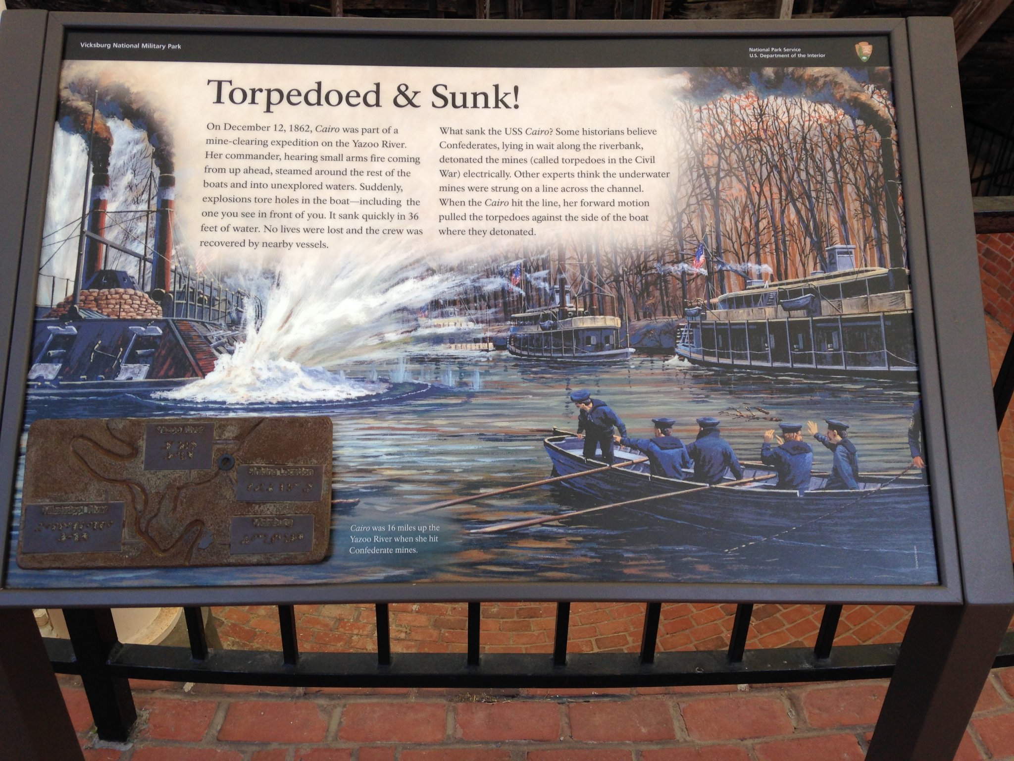
I was digging through some of my pictures and ran across this little gem from my visit to Vicksburg back in 2014. It is one of the information plaques from around the Cairo display showing a painting of her being torpedoed. I'm going to have to go back and do some research on the painting itself to find out if it was Civil War era painted by an eye witness or something done more recently for the exhibit. However it does give a good look at the coloring of the ship (not sure of its accuracy), and it brings about another interesting detail that I might want to add to my build. The sandbags added around the pilot house. I have read that there were many boats that used cotton and hay bales as a armor, mainly a lot of the tinclads and converted packet steamers. So it wouldn't be too much of a stretch for the ironclads to use sandbags for additional protection from enemy fire. Going to have to play around with this idea some more.

-Brian
- GrandpaPhil, FriedClams, BANYAN and 4 others
-
7
-
3 hours ago, wefalck said:
The coamings were given an extra layer of ochre wash to make them look a bit different from the gratings.
That definitely explains the reason for my question. It’s all in the appearance, and from what I see it looks great! Like Keith said, unless you were to put it under a microscope, no one would be none the wiser that it was all one piece.
-Brian- mtaylor, FriedClams and Keith Black
-
3
-
Eberhard, what amazing detail work, on such a small scale! I have troubles painting pieces like this that are double the scale.
So are the floor gratings and the comings two separate pieces or just one? From the pictures the grating looks as though they are framed due to the color differences. Either way, fantastic work!
-Brian
- FriedClams, Keith Black and mtaylor
-
3
-
Lots of tedious work, but the end result will look fantastic! Beautiful job so far on keeping the planks perfectly aligned.
-Brian
- FriedClams and mtaylor
-
2
-
On 11/8/2021 at 10:55 PM, gak1965 said:
Because I am getting near to this point, I have a couple of issues that I want to bring up. As has been said a number of times, the castings for this kit are really awful. Fortunately the pump is not bad, but I have a suspicion that I'm going to replace a bunch of the castings, including the capstans, fife rails, and the figurehead. Just for reference, here are the capstans, water tank and the figure head. The capstans don't look too bad, but the tops are a mess. The water tank is genuinely horrible and the figure head is, I don't know ho to even say it.
George,
I have several Model Shipways kits, both finished and ones still in boxes. In my opinion, MS puts together a fantastic kit, it is a shame that they can't seem to get better quality fittings than the Britannia ones they ship out with their kits. I'm sure it is to keep the cost down, but I would be willing to pay a little extra to have quality fittings included.
As for the recent progress, you are doing a fantastic job! I really enjoy following along on your journey. One of these days I'll get around to digging my Flying Fish out, dusting her off and finishing her. However un-authentic it may be, I love the half moon detail on the water closet. Nice little touch to make the model your own.
-Brian
- Keith Black, gak1965 and Cathead
-
3
-
19 hours ago, wefalck said:
You could tone down the white with a very light oil- or acrylic wash with yellow ochre.
Wefalck,
Another method that I just thought of and may give a shot, is to paint a couple of coats of satin varnish over the white. That may add a slight yellowish color to it as well. Generally the more coats of varnish the yellower the color tends to get, especially over white. I wouldn’t think that a coat or two wouldn’t add too much depth to the color. Worth a try anyway.
-Brian
- FriedClams, wefalck, mtaylor and 2 others
-
5
-
14 hours ago, Cathead said:
I have nothing intelligent to add but feel the need to thank all the smarter people out loud for such a fascinating discussion.
Eric,
Good to see you back! This discussion has definitely proved interesting to say the least. I sure have a “boat load” of info to help me along (insert cringes here). I can’t thank the experts enough for their input.
-Brian
- Keith Black, Cathead, FriedClams and 2 others
-
5
-
18 hours ago, Keith Black said:
I use FolkArt acrylic craft paint, Vintage White # 515. It's not a brilliant white and has very little yellow pigment.
Keith,
I’ll have to give that one a look and see if it can tone down my brilliant white doors.
-Brian
- mtaylor, Keith Black, Canute and 1 other
-
4
-
21 hours ago, mtaylor said:
Have you come across any paintings of the ironclads? They might be a better source for figuring out colors. I think the iron plating was basicaly black cast iron.
Mark,
I’ve seen a few of other ironclads, but none of the City Class boats. The ones that I have run across show them painted in an almost battleship gray or some even with a brownish hue. None that I have seen show them as pitch black. The only City Class renderings I have been able to find have been sketches, drawings and lithographs. Of course all of these are black and white. I would presume that the same painting techniques would have been used on the other boats though, so these could be useful.
-Brian
- Canute, mtaylor, FriedClams and 1 other
-
4
-
1 hour ago, gak1965 said:
Modern AIs that attempt to do this turn out to be almost laughably bad. There are some very old color photographs made by using 3 plates with color filters that can be used.to evaluate how well the AI works, and they tend to do poorly. It's not surprising really, it's like a mod function, there are multiple identical color schemes that will generate the same grayscale image, so how can you possibly reconstruct with the available data?
George K
George, how right you are. I ran across this one during my research. It's not near as bad as some of the ones that I have seen. Some are just downright comical and cartoonish.
-Brian
- FriedClams, GrandpaPhil, Canute and 2 others
-
5
-
3 minutes ago, wefalck said:
Incidentically, there is an interesting article published in 2020 or 2019 in the Mariner's Mirror I think on the paints sampled from HMS VICTORY. They discovered that there was a surplus of red pigment in the ships' allocation after the Admiralty decided to switch from red internal painting to white that the ships used up their red ochre by mixing it into yellow ochre, which resulted in the pinkish colour in which the ships appeared apparently during the Battle of Trafalgar - so much for regulations vs. practicalities
Wefalck,
I recall reading something about that in Daniel's "Victory and Beyond" build here on MSW.
This has gotten me taking a long hard look at my paint scheme. While I am satisfied with the red-oxide color that I used for my hull, I have been contemplating a repaint of everything above the waterline. The more I look at my build, the more I think that it is too black and not realistic looking. Since experimenting with the weathering, I have played around with toning the black down a bit by adding a touch of white and brown into the mix. I haven't quite come up with a color that I am completely satisfied with yet, and now that the topic of lead white coloring has come about, I'm also starting to consider toning the white port doors down as well. These were something that I have not been happy with since I installed them. The seem to stick out way too much.
Personally, I am not 100% positive that these boats were painted pitch black at all. Looking at the pictures, you can see how much darker the ships boats are compared to the ship itself. I am thinking that they may have been a more grayish black instead. But the pictures could be skewing the colors according to the sheen of the paint as well. Some of the more glossy areas would tend to show up lighter than the matte features due to the light reflection. Just more things to ponder as I move along.
-Brian
-
3 hours ago, Roger Pellett said:
From the photos that you posted these appear to be typical US Navy small boats and could have been requisitioned from East Coast Naval Shipyards, assuming that rail connections were available to the Ohio or Mississippi rivers. They could also have been built onsite from drawings provided by the supervising Naval Officer.
Roger, I think I would have to agree more with the first part of this statement (not discounting the second part). During the build of the City Class boats they were scavenging pieces and parts from everywhere to outfit these boats. There was a hodgepodge of armament initially installed on them just to get them going, so it would make perfect sense that the boats would have been requisitioned the same way. The supervising Naval Officer probably sent out the rec that he needed 28 ships boats in the 25' range and accepted everything that was sent his way. This would partially explain the variety of different colors and shapes the different ironclads have in the photos. That and over time some of them would have been replaced from battle damage given their location on the ships. Real easy targets.
-Brian
- mtaylor, Keith Black, Canute and 2 others
-
5
-
23 hours ago, mtaylor said:
I think I'd go with what's in the photo of the Cairo since that's the ship you're building.
Mark, I totally agree. I am going to stick with the black hull and go with a light color (white-ish) for the interior. This will allow me to put a little darker stain on the oars so that they somewhat stand out in the boats.
-Brian
- Canute, Keith Black, mtaylor and 2 others
-
5
-
On 11/15/2021 at 1:16 PM, Keith Black said:
Painting a boat or ship's interior white or a light color would have been beneficial for night vision and the ability to see items within. If a boat was to be used only during daylight hours, interior color wouldn't have mattered.
Keith, this makes perfect sense, and most likely the route that I am going to take. There has been a lot of great input on this discussion. Time to compile it all and see what I come up with.
-Brian
-
On 11/15/2021 at 12:44 PM, bdgiantman2 said:
In my opinion, and I admit that I don't know much about this class of ships, I am thinking that the small boat interiors and especially the oars would be the natural wood colors looking mainly at the USS Cincinnati picture. It's so hard to guess with these old black and white photos, and how much the interiors of any small boats actually were painted back in those times.
Keep up this great model of Cairo, your work is impressive and it's great learning about these vessels.
Brian D.
Brian,
Thank you for the kind words and stopping by.
This seems to be one of the hardest parts of this build, interpreting the color scheme from old black and white photos. The lack of documentation on these boats surely has it's challenges. The good part is that there are so many knowledgeable people on this forum willing to share their expertise and help point you in the right direction. I think that my course of action is going to be taking bits and pieces of all of the info and suggestions that I have been given, piecing them together and seeing what I can come up with.
-Brian
- Cathead, Keith Black, mtaylor and 1 other
-
4
-
On 11/15/2021 at 11:45 AM, wefalck said:
The German regulations actually stated that the floor-boards were to be painted 'stone-grey', whatever that means in reality.
The leather parts would be a tan colour, which includes the leather fenders. I think this adds a bit of colour detail, because otherwise the navies at the time had the habit to slap (white) paint on almost everything (there was an old sailor's wisdom: what moves is being saluted, what doesn't move is being painted ...).
BTW, are you aware of this building log:
It's a New York-built naval cutter acquire by the Italian navy prior to 1861 to replace a storm-loss. The original is preserved in the naval museum in Venice.
Thank you for the excellent info Wefalck, this gives me some direction to take with my oars. As for Druxey's build, this was my first time seeing it and it has definitely sparked the creative juices to flowing. There look to be several ideas of inspiration to use in my boats.
-Brian
- mtaylor, FriedClams, Cathead and 2 others
-
5
-
7 minutes ago, Canute said:
Of note, that last picture is the USS Onondaga, a twin turret monitor, launched in 1863. She supported Union forces along the James River till the end of the war. She was sold to France in 1867.
Ken,
Thanks for stopping by and for the info. I thought it was a Monitor, I just had not researched which one. Nice little tidbit of history to file away.
-Brian
- Canute, mtaylor and Keith Black
-
3
-
Wefalck,
What a great bit of information, and it is very much appreciated.
It does seem that a lot of the worlds navies employ some of the same procedures and methods, I would think that this would have held true in the 1860's as well.
Here is a question that I just started pondering as I was writing this. When the City Class Ironclads were designed and built, they were done so under the U.S. Department of the Army. It wasn't until later on in 1862 that they were transferred to the U.S. Navy. Originally, they were crewed by the Army with several Navy men on board to assist. I wonder that if when they were built and commissioned, did the Army follow Navy standards or did they develop their own. If the latter is the case, then they may not have the standard paint schemes as Navy vessels.
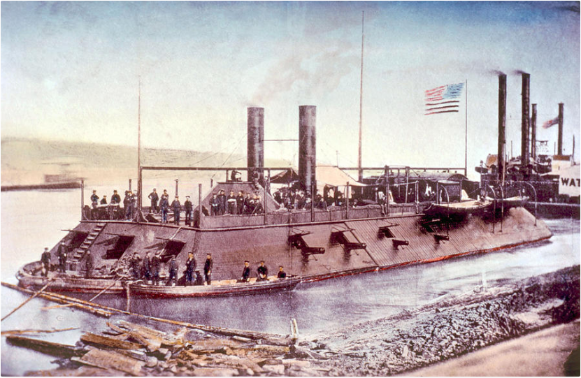
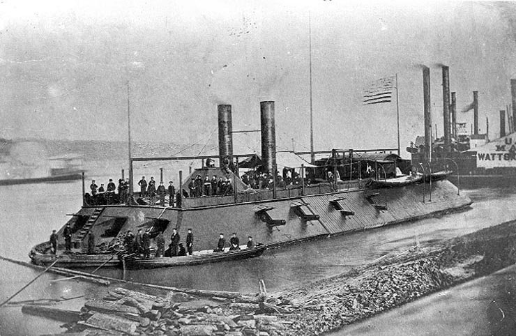
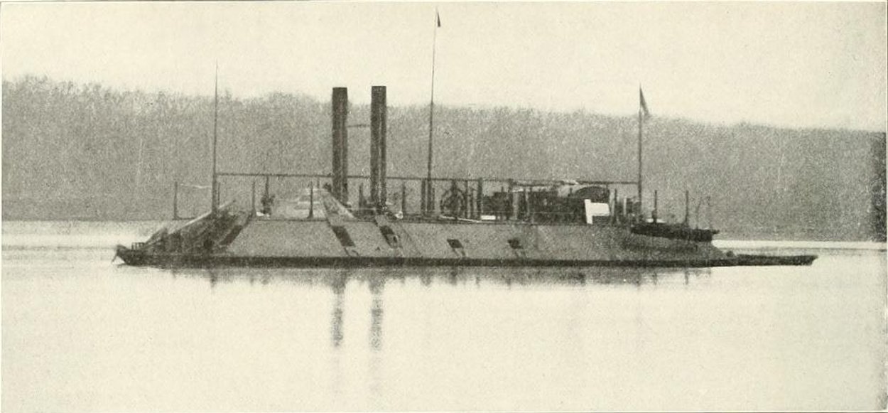
The only known picture of the Cairo was taken shortly after her launch which would have placed it under the Army at the time. This picture clearly shows the boats had black hulls and white interiors, which follows the standard listed in your previous post. However, in the pictures of other City Class boats, some of their boats have white hulls and and white interiors while others others have black hulls with dark interiors. None of the pictures that I have been able to find that show the ships boats have a date on them, so it is hard to tell what timeframe they were taken. This makes it difficult to determine if they were still under the Army or had already been handed over to the Navy. There are also several other pictures that clearly show some of the modifications that took place over time, one would assume that they were after the Navy took possession late in 1862, but none of them show the ships boats in them.
USS Pittsburgh. Ships boats with black hulls, white stripe and white interiors.
.jpg.4797ee95bb718aa0a6c743904cc8e99c.jpg)
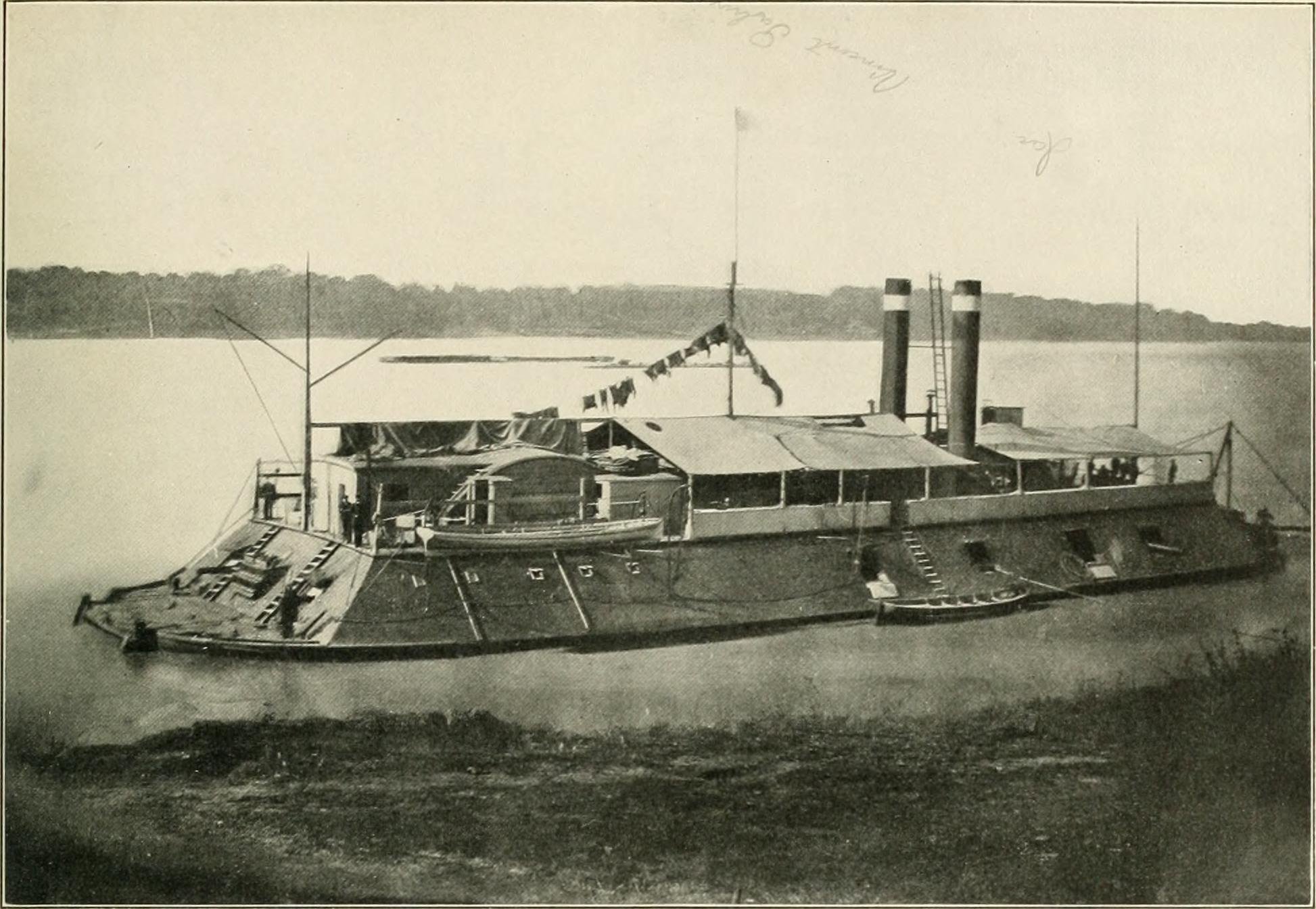
USS Cincinnati: Ships boats with white hull and white interior and another with a black hull and white interior.

USS Cairo: Ships boats with black hulls and white interiors.
USS Louisville: Ships boats with black hulls and what looks to be black interiors.
The more I think about this, the more I believe I'm headed down a rabbit hole where it may take a whole bottle of red and blue pills to get out of. It really seems that the possibilities are endless as to what the colors actually were so I believe that I may just keep it simple and paint the hull exteriors black and interiors white with the oars stained a somewhat dark natural color. I'm contemplating either a rope wrapped handle or simulated leather sleeve just to add some additional detail and leave it at that. For the floor boards, I'll keep the stained wood look to offset the white interior and throw in some rope coils and possibly a few other odds and ends. I apologize for being long winded on this, and thanks for bearing with me. Sometimes it helps me make a decision when I write out my thought processes.
-Brian
- Canute, FriedClams, GrandpaPhil and 5 others
-
8
-
2 hours ago, mtaylor said:
If I remember right, the rope wrapping was to protect the oarlock (as such that it was) and the oar itself from wear. It also silenced pretty much the oar made during rowing.
If all else fails, just put a cover on the boats. But then again, no one can actually say that the oars are the wrong color.
Mark,
The rope info is very much appreciated. I may just have to add this little detail into my oars.
Originally I was going to cover all but one of my boats, and researched several videos and articles on how to simulate tarps, I just felt that this wasn't a technique that I was ready to take on just yet. I felt that it would take me a while to get it done correctly, and I just didn't want to chew up that much time, time that I could be focused elsewhere on my build. Some day I may play around with making tarps, but I think that right now I want to learn how to properly weather this build, and learning two new skills would really task my little pea brain.
-Brian
- Canute, Keith Black, Cathead and 2 others
-
5


SMS WESPE 1876 by wefalck – FINISHED - 1/160 scale - Armored Gunboat of the Imperial German Navy - as first commissioned
in - Build logs for subjects built 1851 - 1900
Posted
What a great method for simulating the portholes. Those look fantastic.
-Brian