


mbp521
-
Posts
1,003 -
Joined
-
Last visited
Content Type
Profiles
Forums
Gallery
Events
Posts posted by mbp521
-
-
Hello again Everyone,
I know it has been a while since my last update. Progress has slowed to a crawl lately with other projects taking priority while I can get to them. Lots of physical labor involved, and by the time I am done for the day I am just wore out and just want to kick back in the recliner and relax with a cold beverage. Temps are starting to get a LOT warmer here so I may spend some of the hotter parts of the day at the workbench instead of baking in the Texas sun.
So with my lame excuses out of the way, I did get a little work done this past week, and I do mean a little.
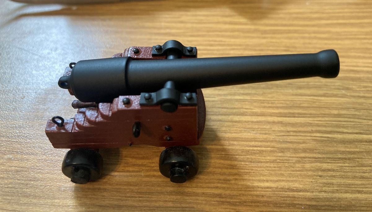
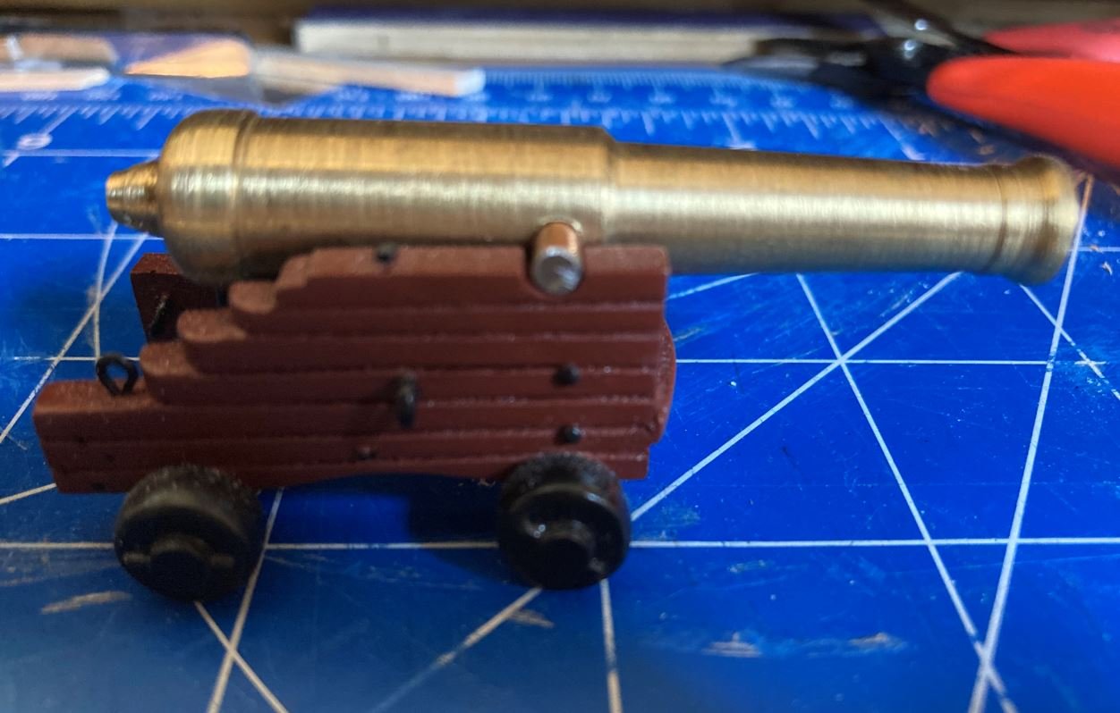
I painted up one of my cannons and assembled it to the carriage. Haven't got the rigging done on it yet, I'm still sorting out how to do that. It's hard to find a good layout of how these were setup. I thought of just using the standard cannon ring for all 19th century American war ships, but the thought occurred to me that the cannon ports were also used as access to load stores and munitions, so the cannons would have most likely been pulled out and turned sideways to make room for the supplies being loaded. So the more I pondered it, the more frustrated I got on trying to figure it out and finally just set them aside for now.
Anyway, here is the 30lb Parrot Rifle in its carriage.
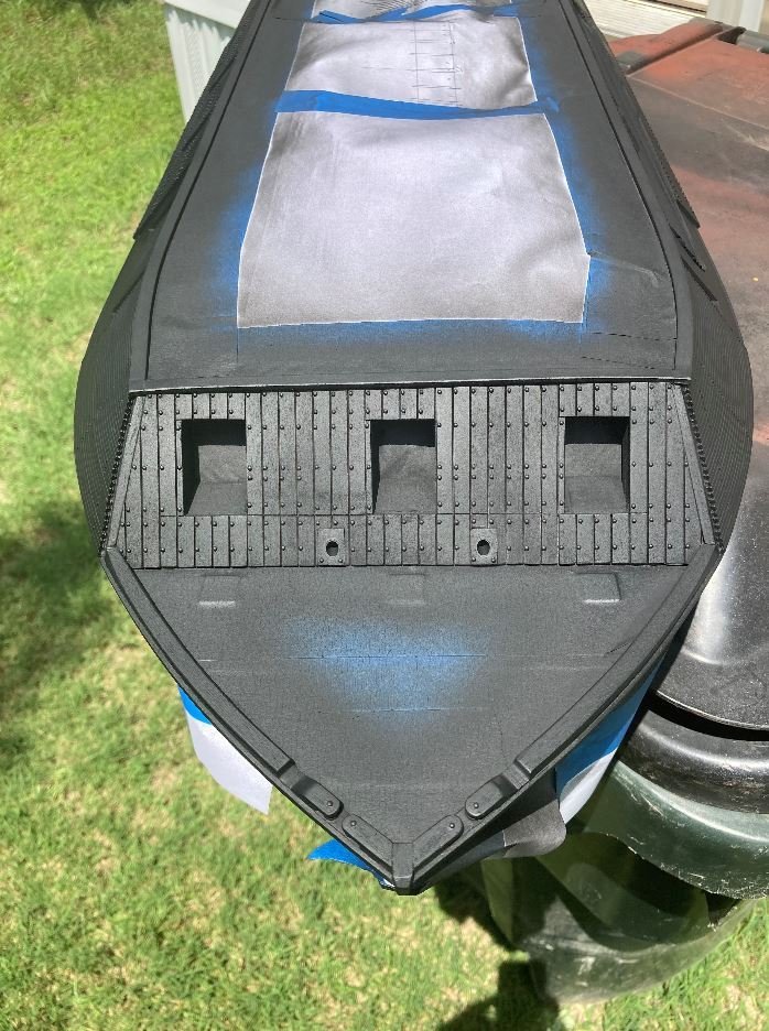
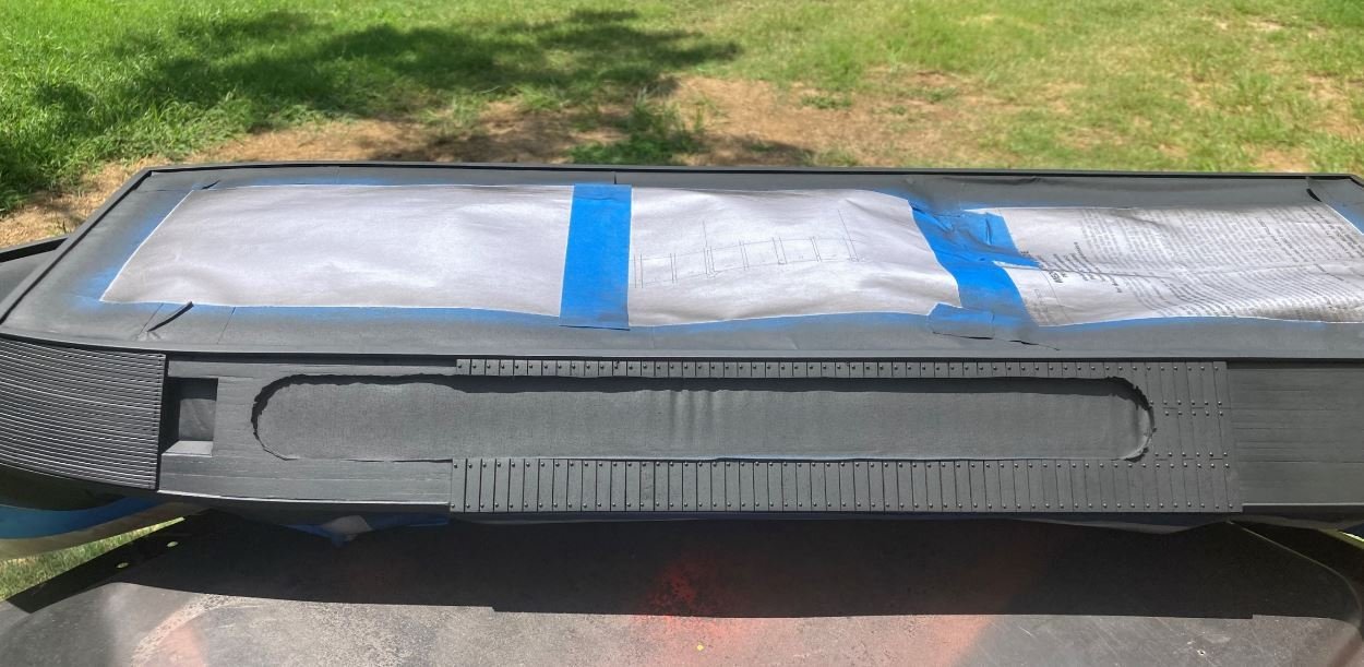
Next up I decided that she finally needed a coat of paint. I'm almost to the point that I'm ready to start installing the cannon port doors, and rather than go through the trouble of painting twice I decided to go ahead and get the casemates painted up so I can then place the painted doors and make minor touch ups as needed. I think that I am going to go with all port doors in the open position. This will allow for somewhat easier viewing of the inside details, not to mention it will save me from having to get the cannons all perfectly centered on the pierced hole with them closed.
First coat of black going on the bow casemates.
Port first coat.
Bow after three coats of black and three coats of satin clear. I did a little texturing with the back paint on the armor plating to give it a more "wrought iron" look and feel. I thought it came out looking pretty good.
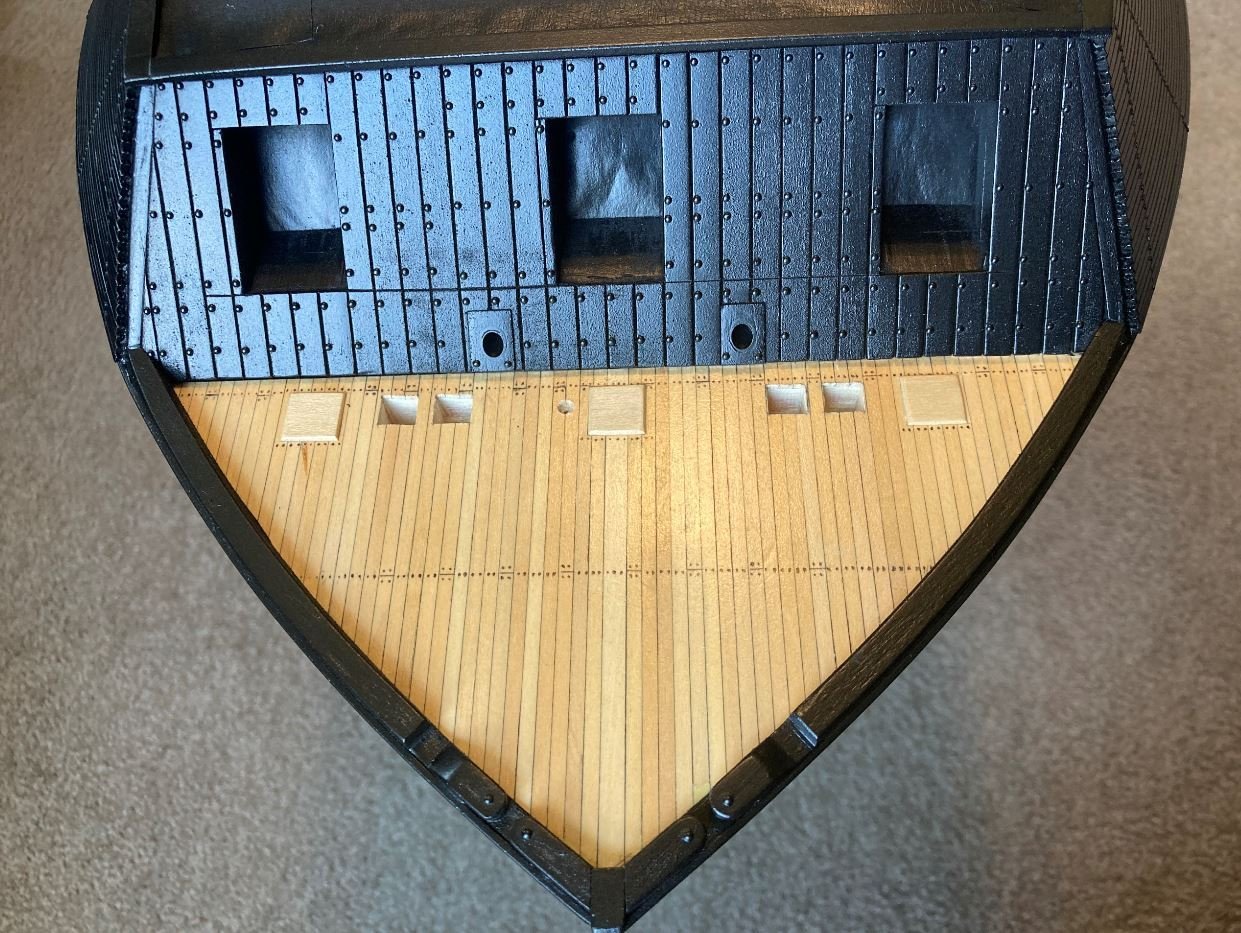
Painted port side. I am still debating with myself as to whether or not I want to paint the inside edges of the viewing port red to symbolize the cutaway. I see this on a lot of cutaway sections and I like it, even the guys working on the St. Louis are doing it, I just don't know if the red will stick out too much and detract from the rest of the model. I still haven't made the decision yet, but there's still plenty of time.
Painted stern
And finally the overall boat painted and all masking removed. It's amazing what a few coats of paint can do to the look. It's really starting to look like an Ironclad.
That all for now. Thanks for sticking with me on the slow progress. Hopefully I can get more done in the coming weeks.
Until next time, I appreciate all the great comments and likes.
-Brian
- Cathead, Nunnehi (Don), FriedClams and 17 others
-
 19
19
-
 1
1
-
Eric,
In my opinion she looks great. I think the figureheads add a nice touch (authentic or not). Your build pretty my represents what I have always envisioned Viking ships looking like.
I am with you on the the deck crowding. This was a subject that I wrestled with on my last build. Where to draw the line at too much. I think you have just the right amount to get the point across of what these people traveled with without the deck looking too cluttered.
I have been toying with the idea of entering my Chaperon in the NRG photo contest, just not sure if my photography skills are there yet. Not to mention our farm projects have really eaten up my time as of lately.
Really looking forward to seeing the final rigging and it’s in place. I know you’ve had your struggles with this build, but you have definitely overcome them and produced a great looking build.
-Brian
-
-
Vlad,
Even with all the trials you are facing so far, she is still looking good. Besides, has there ever been a scratch build that has ever gone smoothly? With your skills though I’m sure they will not be much of a problem for you.
-Brian
-
11 hours ago, mtaylor said:
Good work on the port doors. So they were actually pierced then? For some reason, I thought they would be solid with no gun port. And that's great finding Parrot guns. They will look perfect.
Mark,
Thank you for the kind words. The pierced port doors were almost a necessity. These boats carried some big guns on them and would have taken up a lot of limited real-estate on the gun deck if they were stowed inside. The 42 & 32 pounders alone were over 10.5 feet long and weighed over four tons each. Without them being stowed through the doors the way they were, they would have been an imposing item to have to maneuver around during daily life onboard.
I am extremely happy with the guns (I think I may have mentioned that before). I'm glad I went the route that I did instead of the wooden ones. Thankfully my uncle was able to direct me to his friend who is a machinist. It took a while for him to get them done, but they were worth the wait. I'm anxious to get them cleaned up and dressed to see how they are going to look rigged and in place.
-Brian
- FriedClams, Canute, Keith Black and 3 others
-
6
-
14 hours ago, Keith Black said:
Brian, very nice work. Nice to see a update, good to have you back.
Keith, thank you. Good to be back at it. Funny how being away for a couple of weeks tends to draw you back in.
-Brian
- Keith Black, FriedClams, Canute and 2 others
-
5
-
14 hours ago, BANYAN said:
Nice photos and good progress Brian; looks like the adult beverages provided some incentive
")
cheers
Pat
Thanks Pat. The beverages definitely helped. They also may be the reason I got careless with my drill press on one of the doors.
-Brian
- mtaylor, Cathead, FriedClams and 1 other
-
4
-
14 hours ago, leclaire said:
Brian - thanks for showing the screw up with your drill. I was beginning to believe you never made a mistake like us mere mortals who follow your magnificent work.
Bob
Bob,
Thank you for the kind words, but I am definitely mortal. I could probably make a whole build log out of just the mistakes I’ve made on this build alone. 😁 I usually don’t post too many of them unless I think they can be beneficial to other builders.
-Brian
- Canute, Keith Black, mtaylor and 2 others
-
5
-
Hello everyone,
Finally back at it after a well needed summer vacation. Took a nice little stroll along the Bourbon Trail in Kentucky viewing some beautiful country and giving my liver a good workout. Picked up several bottles of tasty adult beverages and I am now ready to get back at it.
This past week I wasn't able to get too much done, but I did take a lot of pictures. So this go-round I started working on the cannon ports and doors. This was a fairly simple task, and I wanted to get them done so that I could start work on painting the casemates. I wanted to paint the casemates and the doors all at once so the color stayed uniform.
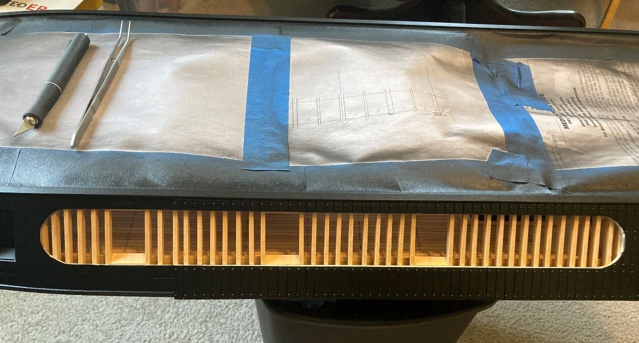
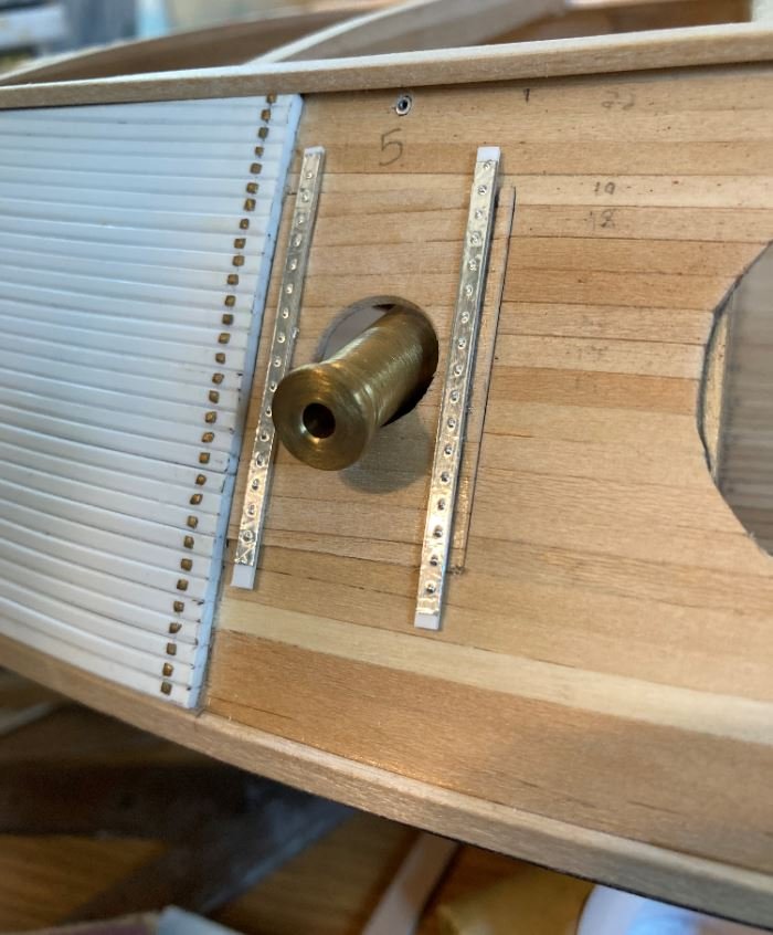
First task up was to install the sleeves for the upper door ropes (not sure of the proper terminology of these).
For the sleeves I used some small aluminum tubing inserted into a small hole that I drilled above the cannon ports.
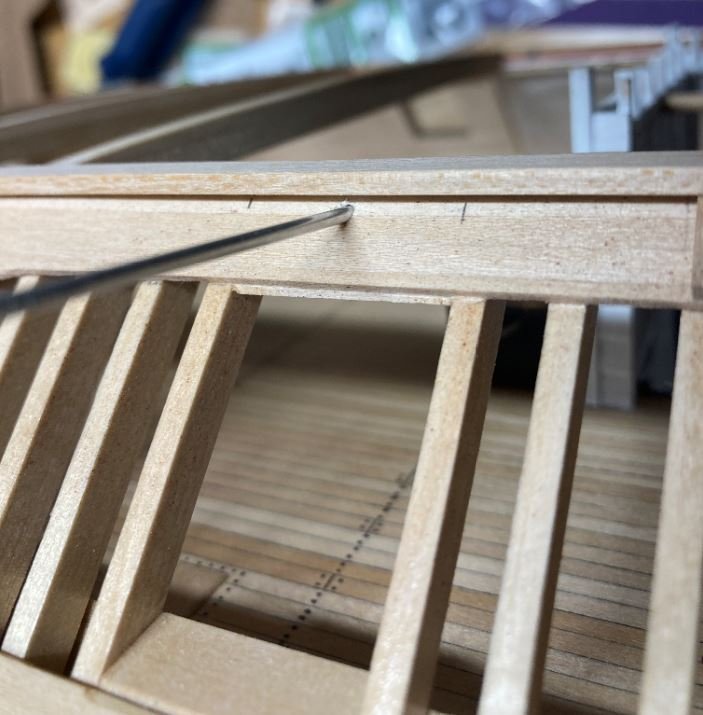
I traced the angle on the tubing then cut and filed it to shape.
Then inserted the tube and glued it into place.
...One down, twelve more to go.
Then it was on to the port doors.
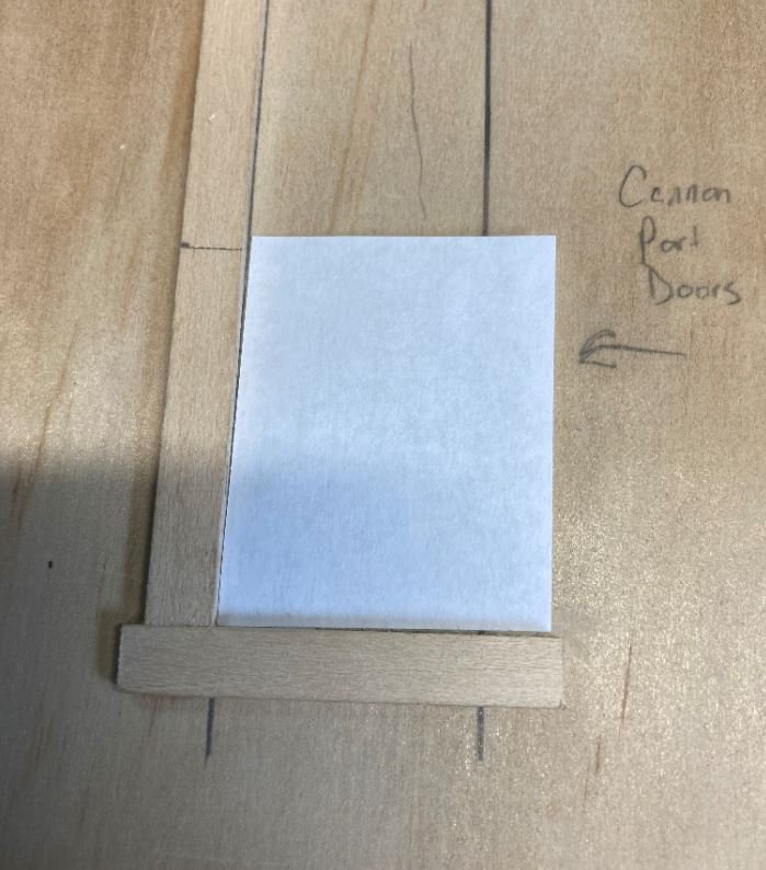
First thing I did was to make up a simple jig to make sure the doors stayed square and uniform.
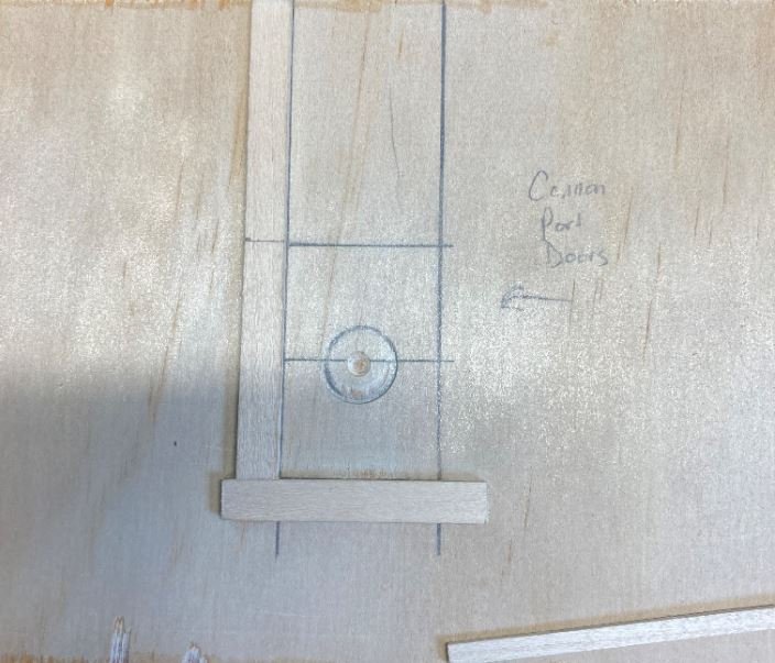
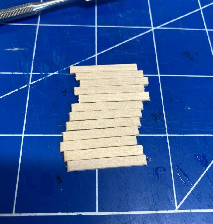
Next I cut the strips for for the individual door planks.
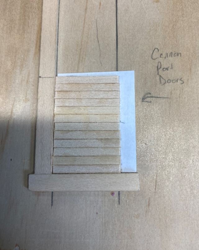
After the strips were cut I used a piece of paper for the backing to help hold things together.
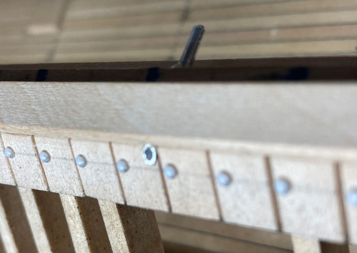
Once the planks were glued into place, I then drilled the cannon port out.
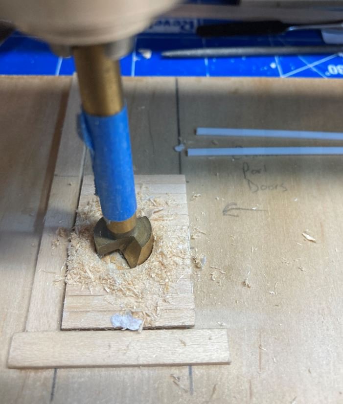
Oooops. Got a little careless with drill.
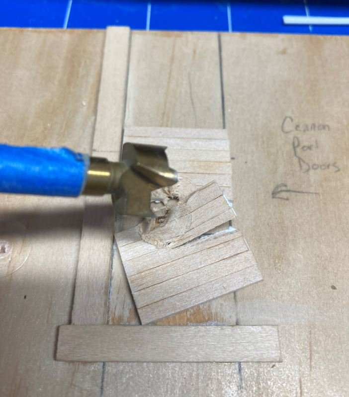
Front port doors in place.
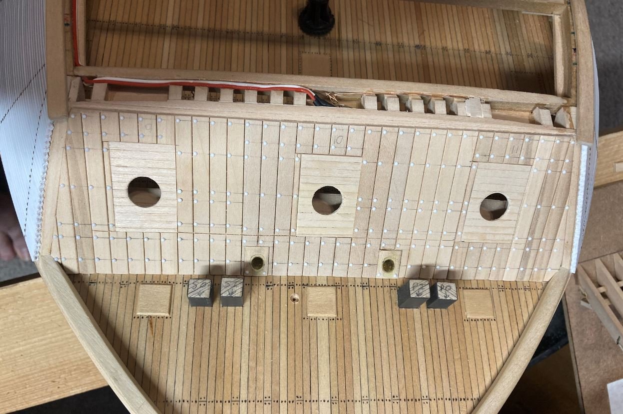
Port doors in place. For the hinge straps I used thin styrene strips that I will cover with aluminum tape with the rivet pattern punched into it.
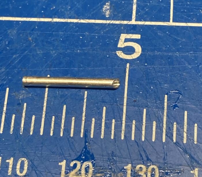
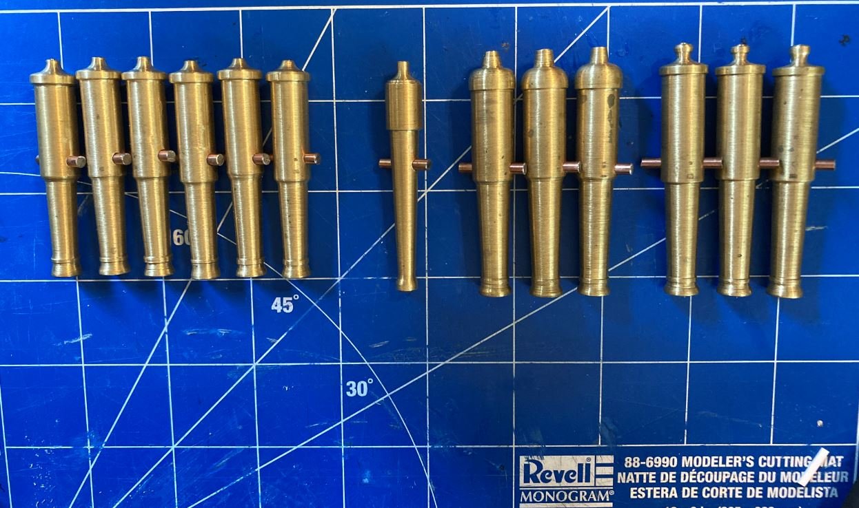
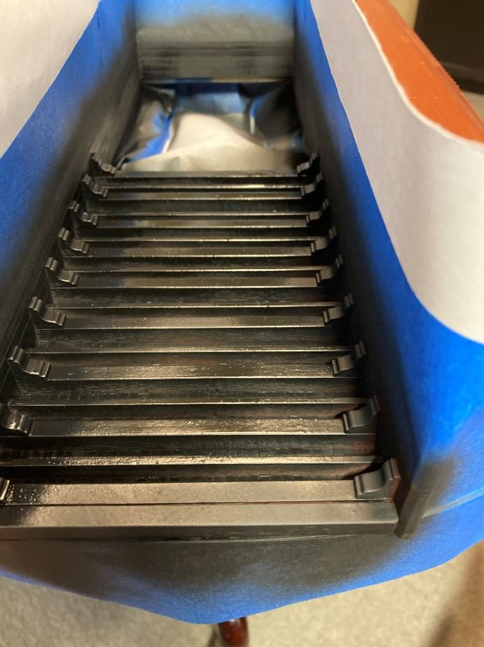
Finally, upon my return from our trip I was extremely happy to see that my cannons had finally come in. There is still some work to be done on them, they need to be polished up to remove the milling marks, the bores drilled to the correct diameter and the necks and knobs will need to be filed to shape, but I am definitely please with the way they came out. They are a definite improvement over the wooden ones I attempted to make a few months ago.
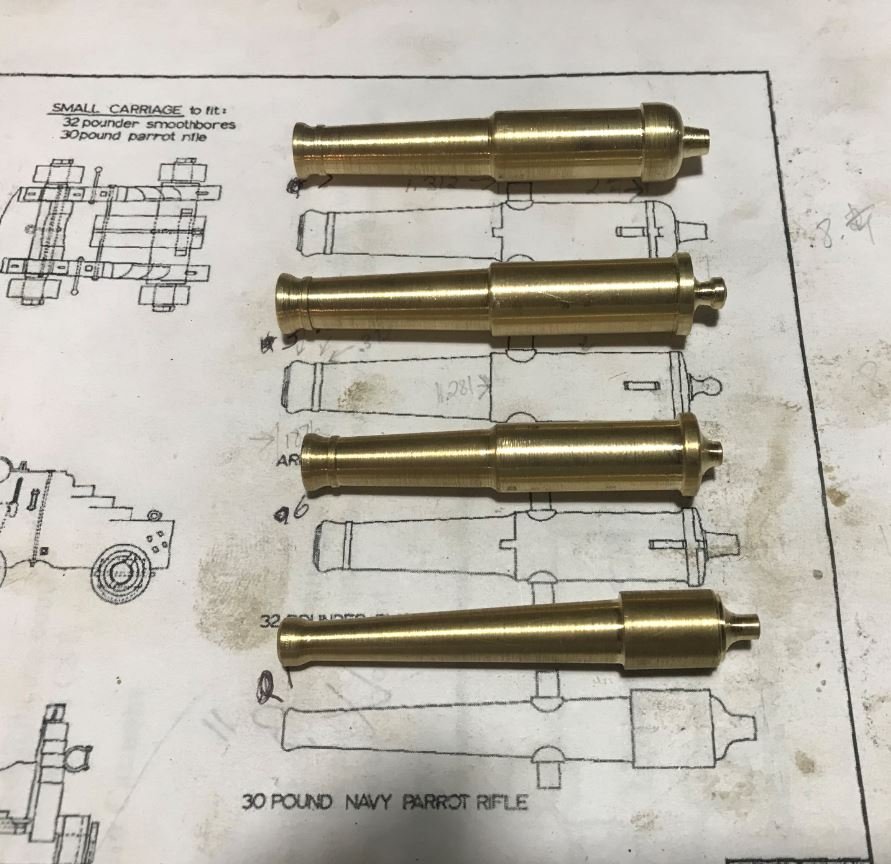
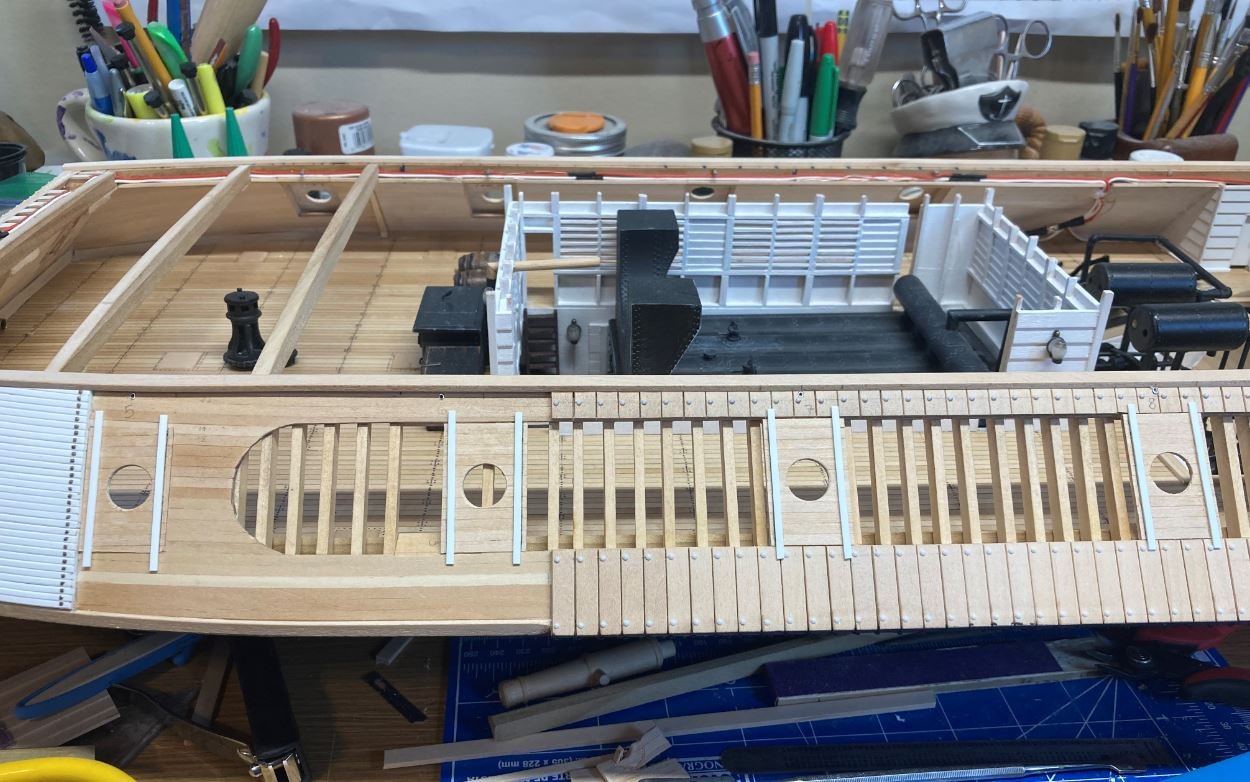
One cannon mocked up in its carriage.
...and finally one set in the gun port. Looks like there will need to be some adjustments made to get the height right, but I'll get there.
Well that is it for now, thanks again for all the likes and kind comments and also for stopping by.
-Brian
- bruce d, leclaire, Keith Black and 12 others
-
15
-
Great start Vlad. Nice job on getting that backbone straight. Looking forward to more updates.
-Brian
- mtaylor and Vladimir_Wairoa
-
1
-
 1
1
-
George,
Amazing job on the deck. Even without the nibbing strake it came out looking great. I would have to go with the case of the planks not being a consistent width as to having to place filler planks in, I have yet to build a deck that had all of the planks the same size. A task that I always say that I am going to watch for next time, but next time never seems to come.
I may sound like a broken record, but I have never been a fan of the Britannia fittings that MS puts in their kits. Most of the time they are misshapen, or there are voids in the casting, and almost every time there is an over abundance of flashing.
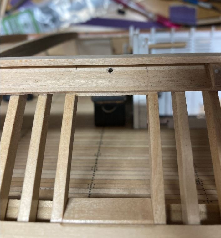
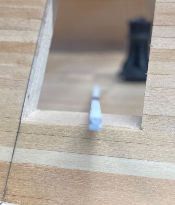
It has been several years since I built this part of the ship, and really don’t recall how I assembled this part and unfortunately most of it is covered by the forecastle deck. However, in looking at my build I have the hawse pipes directly in line with the windlass. Now going back and looking at the plans, I’m not sure I did this correctly. I tried to get a snapshot of mine taken through the bowsprit hole but it wasn’t too clear. You may be able to see the deck level in relation to the hawse pipes.
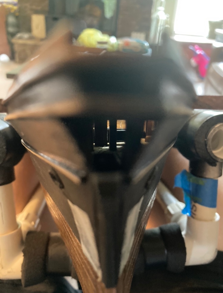
Hopefully this will help. Keep up the great work.
-Brian
- Cathead, Vladimir_Wairoa and gak1965
-
3
-
Eric,
Finally catching up on your build. The oars look great!
Just my opinion to your posed question on how to display the oars, personally a display having them all spaced evenly apart looks great with a build that has no weathering, but in the case with yours, semi-chaotic, but slightly swept back would go along with the weathered theme you have going on.
I also agree with Gary, great job on getting so many pieces to look uniform. One of the details I still struggle with without a jig.
-Brian
- mtaylor, Cathead and FriedClams
-
3
-
Keith,
Catching up on your build. Love the display case, man what a great find.
I have yet to do a build that didn’t come with a rigging plan (never done a scratch build of a full rigged ship), and at this point I hope that I don’t have to. But on the bright side, at least you only have to figure out half of it, since for the most part everything will be mirrored between the port and starboard sides. 😜
Seriously, keep plugging away at it though, you’ll get there.
-Brian
- Keith Black and FriedClams
-
1
-
1
-
1 hour ago, BANYAN said:
If that is pedestrian then my current build will be relegated to prehistory before it is finished
 At least five years on this one and I am just starting the spars and rigging.
Pat,
Not sure if it will take me five years on this one. Hopefully not, but I’m sure I have at least another one, possibly two. Can’t go too long though, I have other builds that I’d like to get to.
-Brian
- Canute, Keith Black, Cathead and 3 others
-
6
-
George, Keith & Wefalck,
I very much appreciate the condolences. I’m sure as time goes by things will get better.
The pedestrian progress is the one thing I am trying to avoid. I know sometimes it’s hard to avoid, especially when the weather turns nice and you have an over abundance of outdoor projects that seem to take precedence over shipbuilding. Drawbacks of owning acreage, there is always work to be done. Hopefully the work won’t creep too much into my build time and I can keep everyone updated and interested.
-Brian
- Canute, Cathead, FriedClams and 4 others
-
7
-
On 5/22/2021 at 4:54 PM, Cathead said:
Brian, that makes a ton of sense. I can easily see how trying to shape actual brass rails in a consistent and parallel shape could be maddening, and how much easier styrene would be. Again, you'll be in my thoughts as we go through a similar period.
Eric,
it was definitely a challenge to get the brass rails to work. I even went so far as to try heating the brass to get the twist to hold its shape, but it was just too difficult. I usually try to go by the 10% rule (be 10% smarter than the thing you are working on) but in this case I just conceded defeat and moved on. All in all I am happy with the results.
-Brian
- FriedClams, Canute, Cathead and 2 others
-
5
-
On 5/22/2021 at 2:03 PM, vaddoc said:
My condolences Brian. I hope things get better with time.
You are doing a fantastic work, I am sorry I do not have the time to visit as often as I would like to. Now, I had not realised that the armour plating was actually railroad tracks. The weight must have been very considerable and it is impressive that it is all secured essentially on a wooden frame. I also find very interesting that despite all the armour and guns those boats were still ramming each other.
Your paddle wheel is truly very impressive, well actually the whole model is wonderful. The red oxide paint is very nice.
Regards
Vaddoc
Vaddoc,
Thank you for the condolences and for stopping by. It is truly amazing at the lengths they went through during the Civil War to protect these boats a crews, yet wouldn’t hesitate one bit to go to extreme measures to take out the enemy, including ramming one another. I have read numerous stories where, gunboats designed as rams (which sometimes were converted packet steamers) would sacrifice themselves in a hail of gun and cannon fire to remove their foes from the battle. Some truly amazing stories.
These particular gunboats were built for durability, yet didn’t have a long lifespan. Other than the Cairo the longest surviving City Class Ironclad was the was the Carondelet which survived until 1873. All others were sunk during the war or sold for scrap shortly after the war ended in 1865.
As for the red oxide paint, I am definitely pleased with the way the color came out and works with the black. Once I have the casemates painted up, I’m sure it will really look good.
-Brian
- Keith Black, vaddoc, FriedClams and 3 others
-
6
-
2 hours ago, Cathead said:
Lovely work as always. Correct me if I'm wrong, but are those railroad irons just essentially iron rails, and that's why you were looking to source HO-scale track? I wish I'd known, I have a lot of leftover brass track that I would happily have sent you for free. Apologies if I missed that detail early enough to have made a difference. It's been a distracting time here and I maybe haven't been reading as closely as I should? Your approach certainly does and will look great.
Condolences on your loss, I've been there recently too and am still working with the aftermath.
Eric,
You are correct. The irons were just salvage railroad tracks that they used for additional armor plating. I appreciate the offer on the track. If I’d have known earlier I might have taken you up on it. I was struggling to get the pieces that I had on hand to lay down right since their location in the boat is in such a weird place where compound curves and twists are involved, so that was just one of the reasons I went with the styrene instead. The styrene was soooo much easier to work with, especially having to drill all the bolt holes, and I think once everything is painted I’ll have the desired look I was going for.
I appreciate the condolences as well. It was a tough loss for the family. I took it harder than my wife did at first, but now she’s starting to really struggle with it. He’ll definitely be missed.
-Brian
- Cathead, mtaylor, Keith Black and 3 others
-
6
-
20 minutes ago, archjofo said:
there still seems to be interest in my construction report.
Johann, on a build like this, there will always be an interest. Marveling at a master at work never gets old.
-Brian
- Keith Black, PeteB, FriedClams and 9 others
-
12
-
Keith,
Nice work on the blocks and dead eyes, I am filing away your technique for future builds.
As for being all over the place, I am quickly finding out that seems to be the norm (at least for me) on scratch builds. Without a set plan, I just work on what part interests me at the time. But every little bit you get done is a step forward towards completion.
-Brian
- mtaylor, FriedClams, Keith Black and 1 other
-
3
-
1
-
Thank you all for the kind words and condolences.
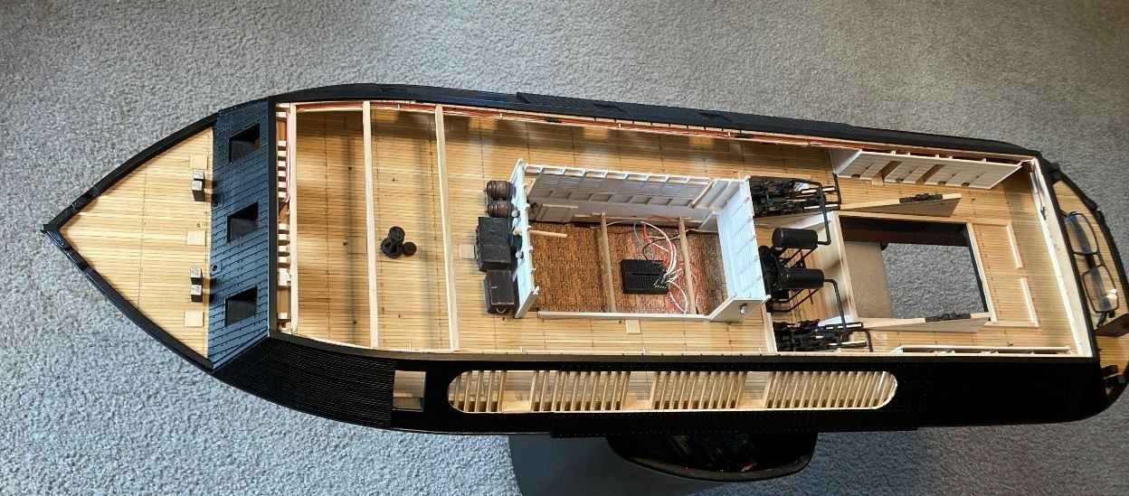
I realized that today marks the one year anniversary since I started this build. I just wanted to show the overall progress after the first year.
Day 1.
Day 365.
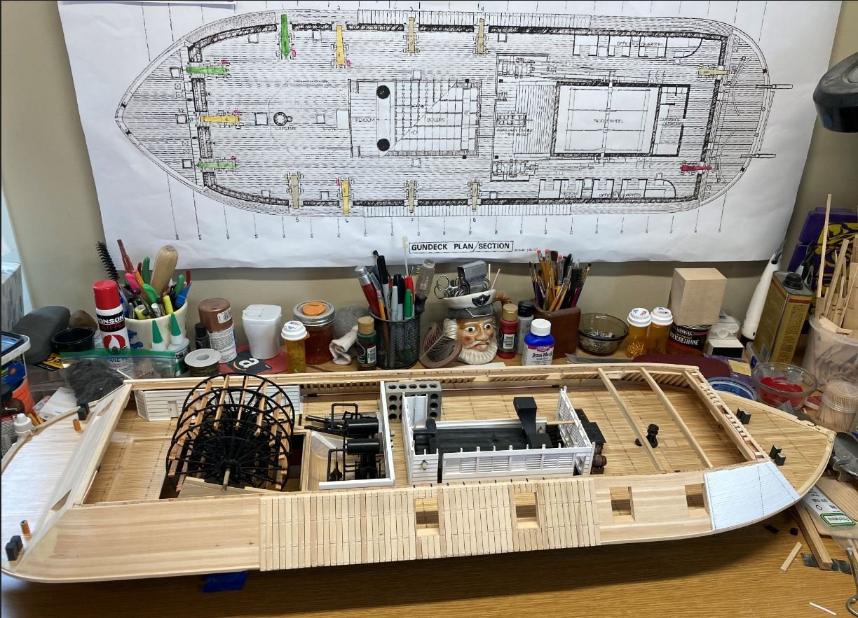
Coming along, and more to come. Thanks for sticking with me this past year.
-Brian
- Nunnehi (Don), Moab, leclaire and 19 others
-
22
-
MCB,
Just stumbled across your build and I cannot get over the uniqueness of this boat. What a fascinating subject and excellent detail you have put into this. Looking forward to following along.
-Brian
- mtaylor, Rik Thistle, Keith Black and 1 other
-
4
-
Hello again Everyone,
I have returned with a brief update. We have been dealing with the loss of my father-in-law a couple of weeks ago and have been out of town getting funeral arrangements and other things straightened out so there has not been a whole lot done lately, but I wanted to get something out there to keep the build log rolling.
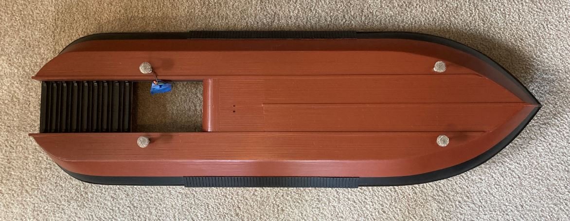
For this update I was able to get the hull painted with another coat of red oxide and a touch of black. I needed a third or fourth (I forget how many coats I previously put on it) red to hide some minor blemishes that occurred moving the model around on my bench. No major damage, just a few nicks. Once the red was dry, I sprayed on three coats of satin clear to give it a good finish. The clear coat also allows for a cleaner, crisper line when taping and painting the overlapping color.
Once all of that had dried, it was time to mark the waterline. Since there is no clear documentation on what color the hull actually was, I was also not able to determine where the actual waterline would have been. So once again, I took my builders liberties and decided that the waterline would be just below the armor plating that sits below the knuckle on the casemates.
First coat of black applied. When I was uploading these, I realized once again that I forgot to take pictures of the progression. Sometimes I just get so involved with what I am doing that I totally space on the pictures.
Three coats of black and another three of clear satin.
Starboard side painted.
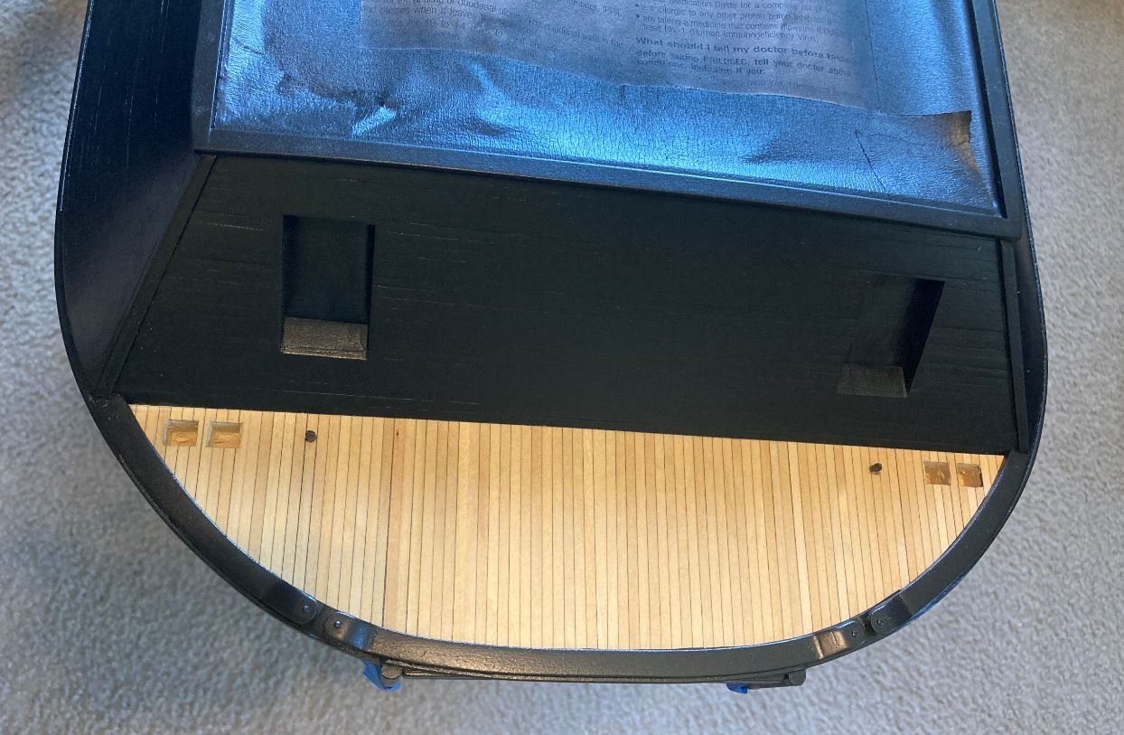
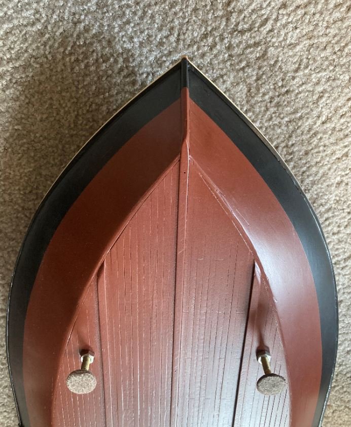
Overview of the hull bottom. The two holes just aft of the center keel are the pickup tubes for the Doctor pump. A little detail that I thought would be neat to add.
Bow bottom.
Stern bottom.
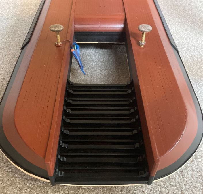
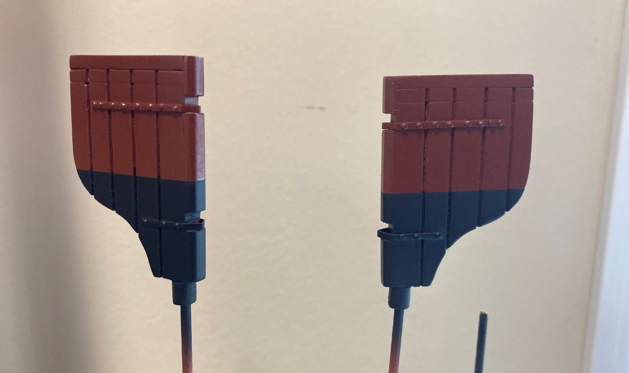
And finally the rudders painted in the same manner. These were a little trickier since I had to get the tape down in the plank grooves to prevent the black from bleeding over.
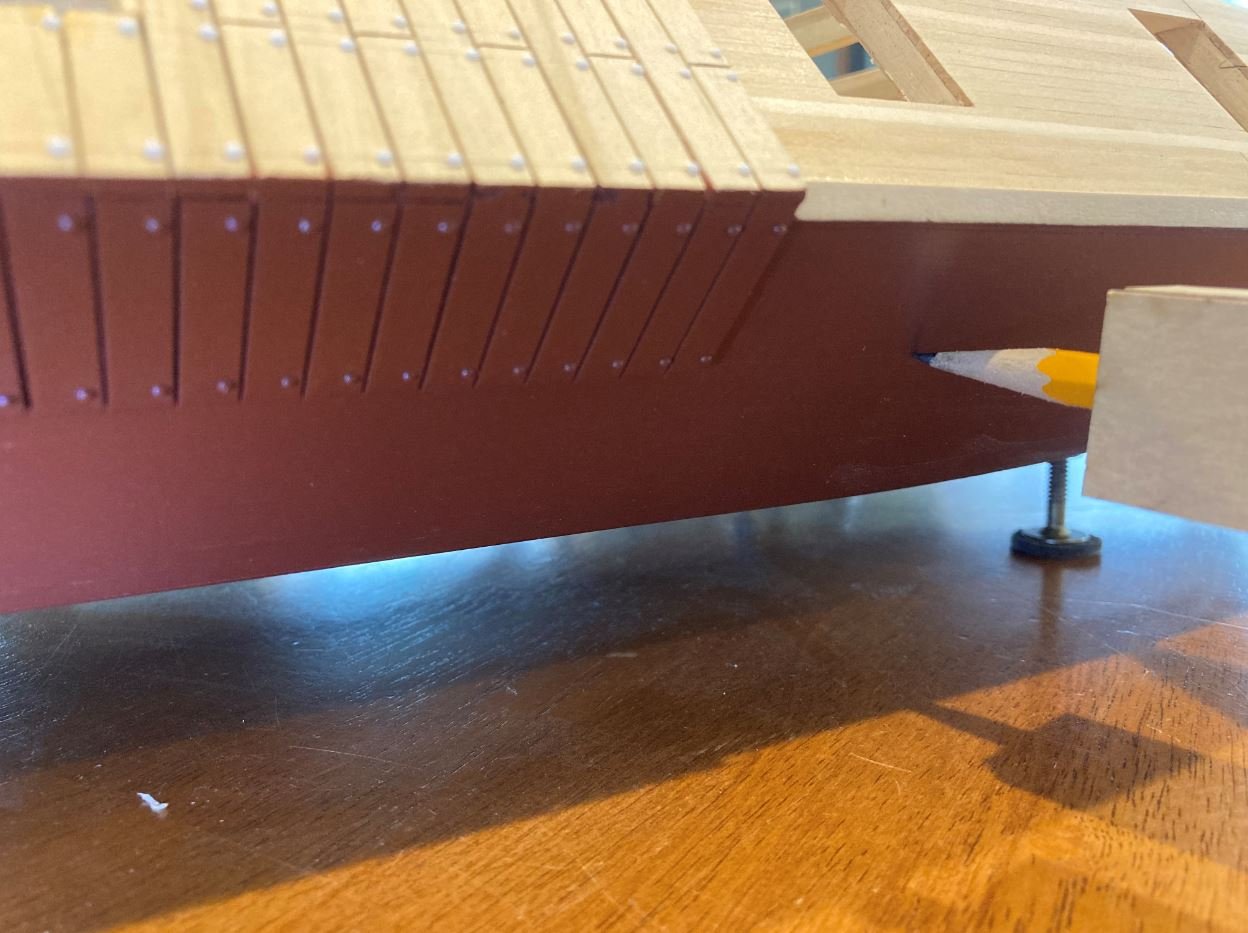
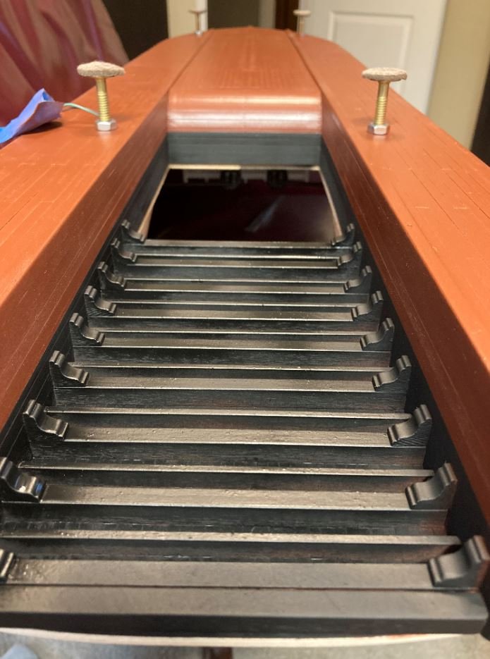
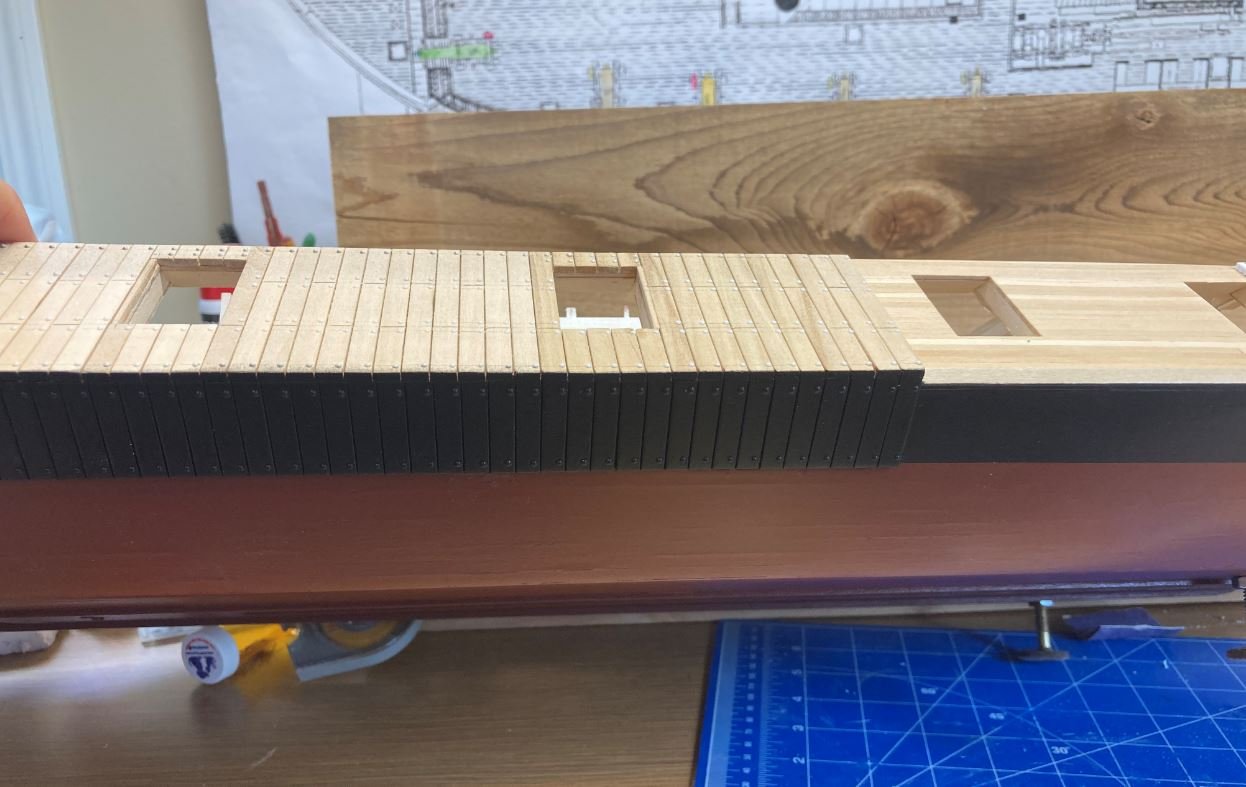
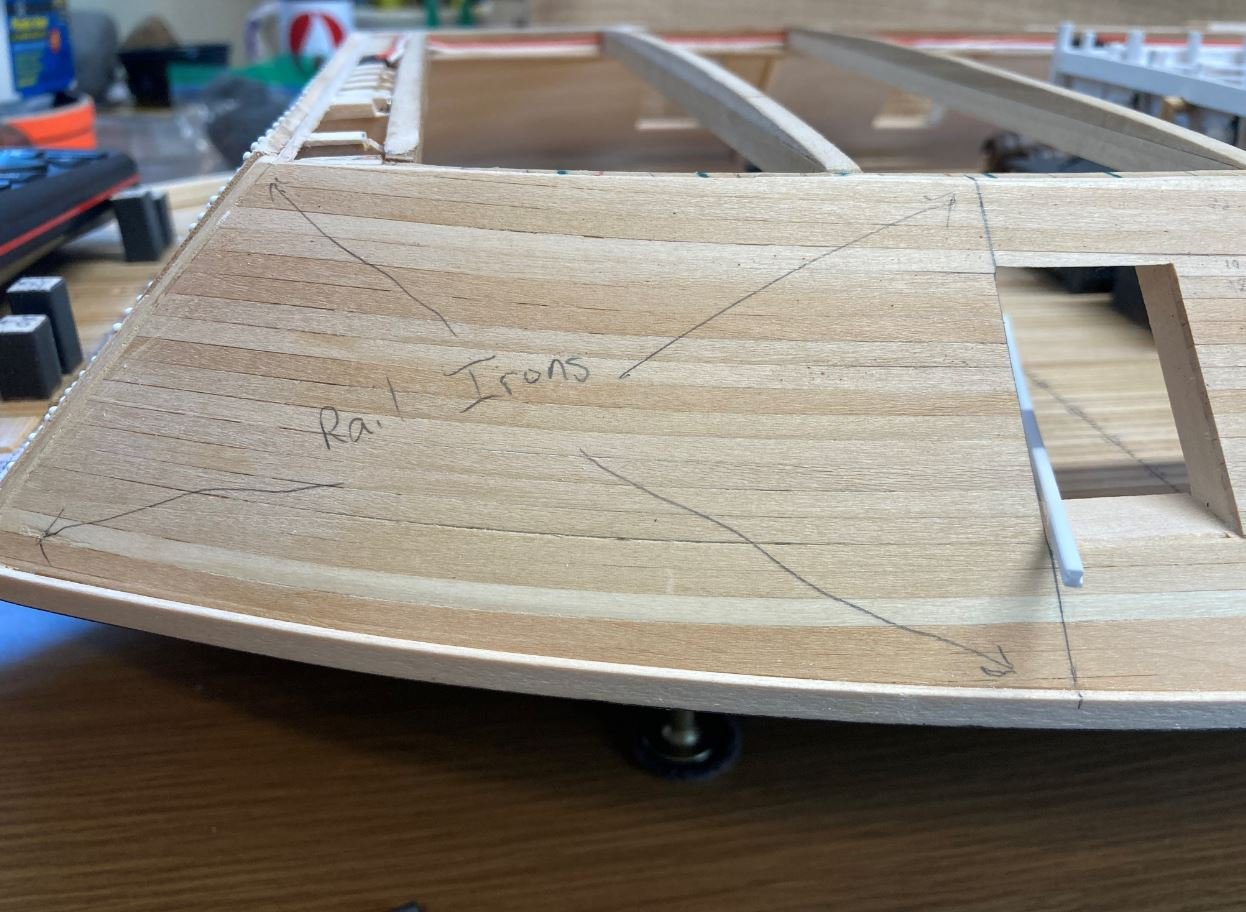
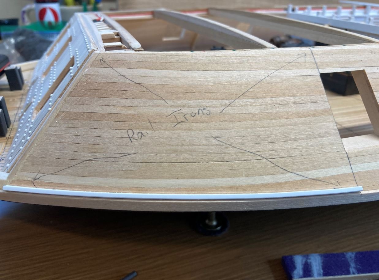
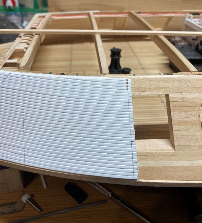
Next up was the railroad iron armor plating. I wrestled around with this feature for a while. I wanted to portray the irons as accurately as possible and had first thought about using actual HO scale railroad pieces. I had a few pieces from way back when that I managed to scrounge up, but not nearly enough to complete the job. I made a couple of test runs with it but the brass was to rigid to get it to form with the contour of the casemate. I also figured that I would have a difficult time getting the glue to hold the brass rails in place. The final straw was when I went online to see what the cost would be to find someone selling old pieces of track and found out that this was not a cheap alternative. I know you can't put a price on a quality build, but the line has to be drawn somewhere. So finally I decided that I would use Styrene plastic strips for the railroad irons instead. I settled on the 2mm x 2mm strips which were the measurements of the brass HO scale railroad tracks. Since these would be placed side by side and only the flat end of the iron shown on top and the ends visible, I decided to just shape each end of each iron to give the appearance of the I-shaped irons.
First row of irons going in on the port side.
Starboard side irons in place and marked up for the bolts.
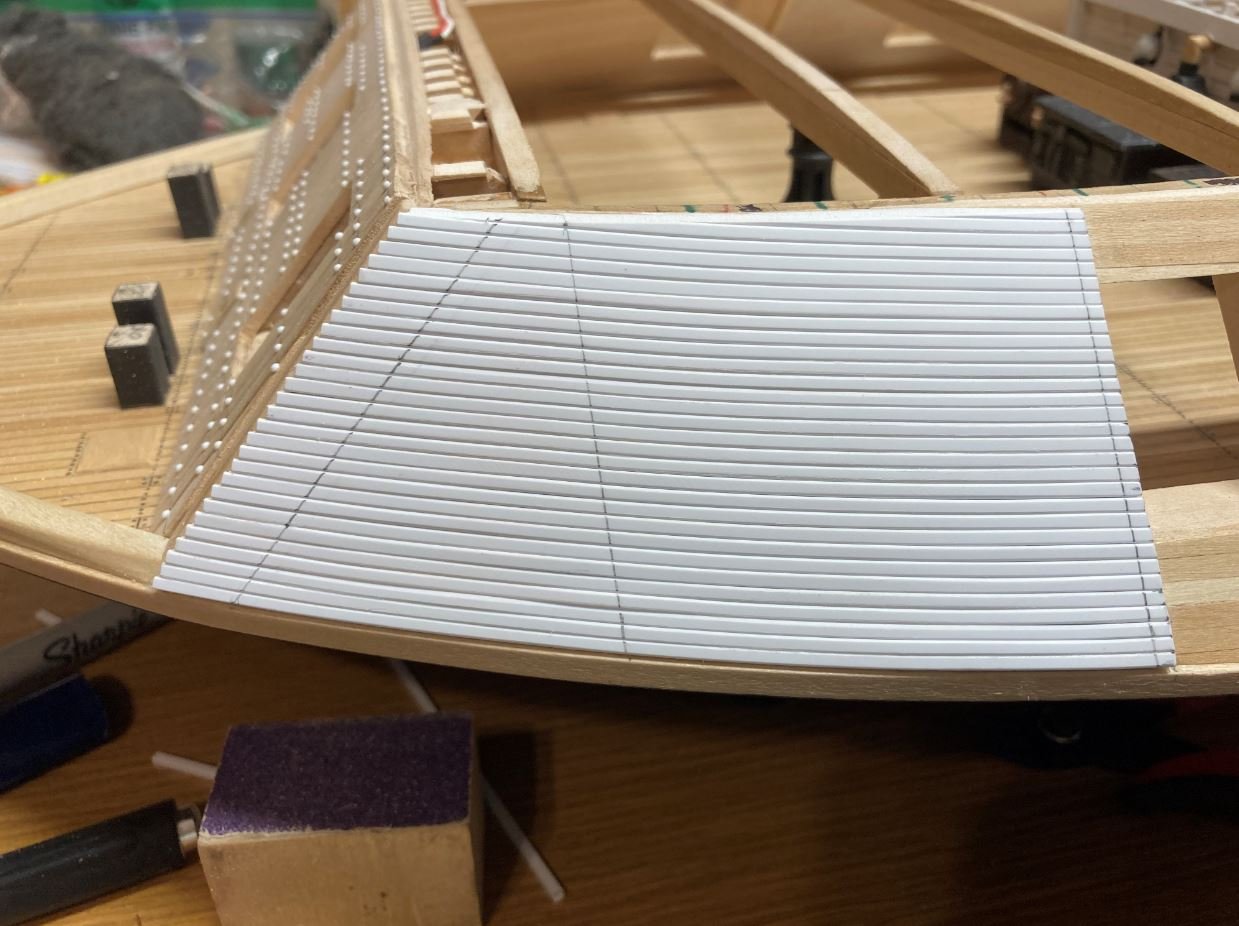
Port side going in.
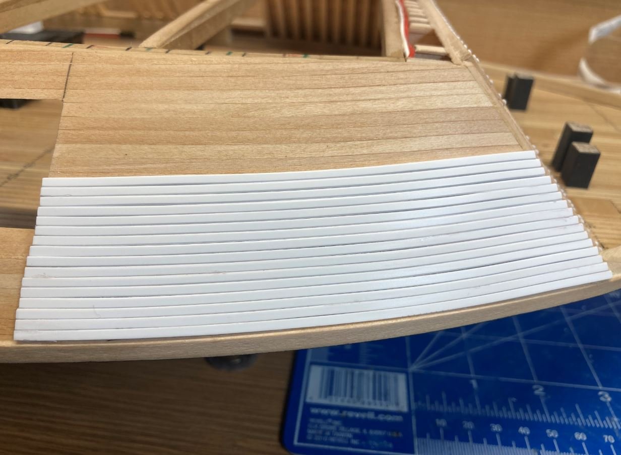
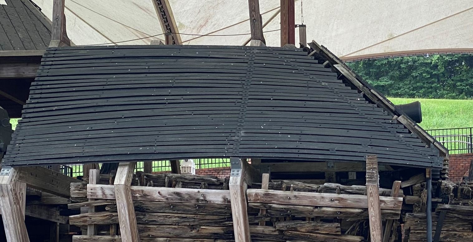
Port side installed. This armor plating was done as an after thought, and a brief history of why is in my previous post #247. Since they were added later on and according to records, most of the work was done by the crew, then they would have been done quick and cheap to get the boats back into action as soon as possible. Since this was the case, I would venture to say that not a lot of effort was put into looks and more into functionality, so care would probably not been take to make sure that all of the irons were laid perfectly flat and even. I tried to replicate this when placing each strip so that they were not perfect. This can also be seen on the actual boat display, albeit the Irons could have been misshapen during the salvage operation. Either way, I wanted to make them look like they were done in a hurry. I'm sure that they won't be as obvious once they have been painted.
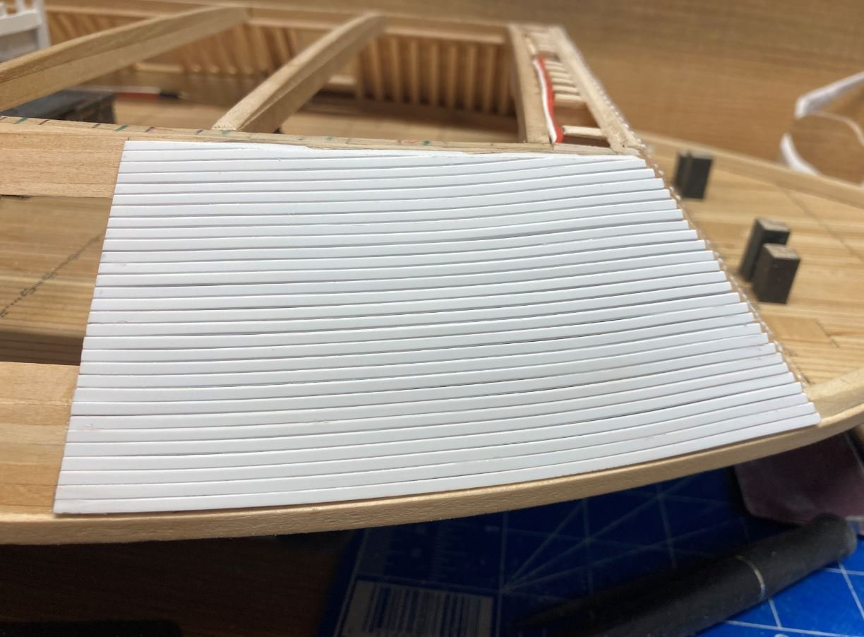
The look that I was going for.

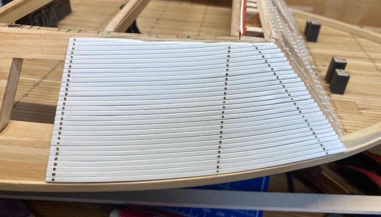
Next up was placing the bolts to hold the irons in place. For these I used tiny brass nails with their heads clipped and filed square to simulate the square bolts and plates used on the actual boat. First few as a test run.
The rest of the holes marked a drilling them out.
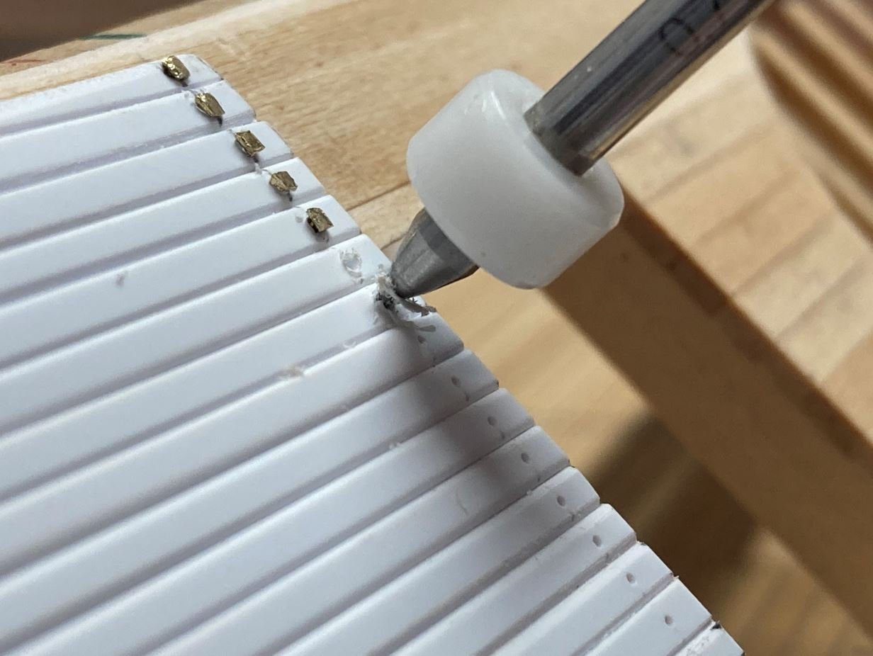
All of the bolts in place on both sides.
During the installation of the railroad irons I found a mistake that I made during the construction of the forward casemates. I didn't quite get the angle correct where the port and starboard sides meet up with the forward casemate at the top. According to the HSR plans, I do have the angle correct on the forward casemate, but somewhere I went wrong when I built out the sides. This caused me to have to trim some of the railroad irons at an angle instead of them being full runs from just forward of the first cannon on each side to the forward casemate. I do apologize now for my mistake, but I was not about to go and tear apart all of the work that has been done on this part for this minor detail. I figured that I would have to live with my mistake and learn from it. Please do not think lesser of me 🙄, but this would be a LOT of re-work, and I do think that I may be able to disguise some of this when the hurricane deck is installed and everything is painted. 😇
So that is all for now, I very much appreciate everyone stopping in and taking a look as well as all the likes and comments.
-Brian
-
Well deserved award Eric. Congratulations.
-Brian
- mtaylor, FriedClams, Canute and 1 other
-
4
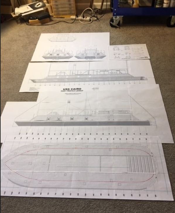
USS Cairo 1862 by MPB521 – FINISHED - Scale 1:48 - American Civil War Ironclad - First Scratch Build
in - Build logs for subjects built 1851 - 1900
Posted
Bob,
Thank you for stopping by. It's mostly when I look back on previous posts of mine that I see a lot more pictures in them than my last that makes it look like not a whole lot of work was done. In reality, the most time consuming work of my last post was masking everything off. The painting, as everyone knows, was a lot of hurry up and wait between coats. Without the wait time included, I had about 10 hours worth of work done. By my normal standards, that is not much over a weeks time. Plus given the fact that it has been a month since my last post, I really feel that progress has slowed down tremendously.
But enough of my rambling, I am seriously thinking of using the reddish-brown color that I used for the hull to trim the cutaway in. It's a nice muted color and brings the color up from the bottom to a more focused on spot without being too distracting. I'll give it a shot and see how it looks. Nice thing about paint, if you don't like the color you can always change it.
Keith,
Thank you Keith. I had pondered that as well, but since I was leaving the framing in its natural color, I wanted to show some separation between the two. Like I told Bob above, I'm going to give the reddish-brown color a try and see how it comes out.
Pat,
Thank you for the input. These great comments are always welcome. I think this is going to be one of my next steps to see how the reddish-brown looks trimming the cutaway out. I'll be sure to post photos of the look, even if I do change my mind and go with a different color.
-Brian