


gjdale
-
Posts
4,894 -
Joined
-
Last visited
Content Type
Profiles
Forums
Gallery
Events
Everything posted by gjdale
-

Dominoff Serving machine
gjdale replied to Don Quixote's topic in Modeling tools and Workshop Equipment
You are spelling his name incorrectly. Here is a link to a post he made just last Sunday, advising of an update to his online shop. I suggest you PM him with any specific questions about spare parts you are after. He is very good to deal with and will go out of his way to help. -
This is a fun little project Dave. You’re off to a good start.
-
Dominoff Serving machine
gjdale replied to Don Quixote's topic in Modeling tools and Workshop Equipment
Not sure where you’ve been looking, but I just checked his website and they are still there: https://www.shipworkshop.com/product-page/sm4-series-serving-machines-wrapping-machines -
vacuum for power tools
gjdale replied to Don Quixote's topic in Modeling tools and Workshop Equipment
Are the tools in fixed positions? If so, you could use some PVC pipe to set up a manifold with dedicated lines to each tool and one plug in point for the vac. You would probably want to incorporate some blast gates so that only the tool in use is getting the suction. -
Ducati 1299 by Moonbug - Pocher - 1/4 Scale
gjdale replied to Moonbug's topic in Completed non-ship models
I’m guessing the driveway shots! I must try that photography trick one day - it’s really cool. -
Eric, Glad to hear you’re feeling better. I think your proposed solution might cause you problems with fitting the grating/hatch coaming. Is the capstan step actually glued to the deck beams yet? If not, I would suggest remaking the capstan step. A small setback for now, but you will be glad later on. As my wife often reminds me - the model is a long time finished…….
-
Ducati 1299 by Moonbug - Pocher - 1/4 Scale
gjdale replied to Moonbug's topic in Completed non-ship models
- 25 replies
-
- 11
-

-

-
Yes Glen, soon…..maybe another week or so while I finish up some other non-modelling projects.
-
Glen, I hit the “like” button not because you found some problems, but because you have a plan to fix them. I know you’ll do an excellent job on them too.
-
Glad to hear you solved the problem Rick. I think all of us (except Chuck) have had to cut several new planks for this model.
-
Glad to hear the surgery went well Rick - welcome back. Re your plank 9, you should be able to use the original AYC sheet it came from as a template for a new one.
- 155 replies
-
- 1
-
-
- Medway Longboat
- Syren Ship Model Company
- (and 1 more)
-
This looks interesting Kevin. I’ll pull up a chair next to the bar and follow along too.
-
Great work Bug. One idea you might try for the “knob” is a drop/blob of PVA. You can relatively easily control/adjust the size this way too.
- 419 replies
-
- 3
-
-
- Victory Models
- Pegasus
- (and 2 more)
-
Sorry to hear you’ve not been well Eric. Hope you recover swiftly and get back to this project soon - it’s certainly worth persevering.
-
Thank you both B.E. And Mark. I continue to follow your own excellent work with great interest.
-
Bob - next up will be my Amati Hannah Ship-in-a-Bottle kit that I received for my Birthday a couple of months ago. But first I have some full size woodwork in the queue. I’m attending another one week hand tools master class next week, and I also have to make a document box that will be a wedding present for my son and his fiancé, who are getting married at the end of next month. I’m starting on that one today.
-
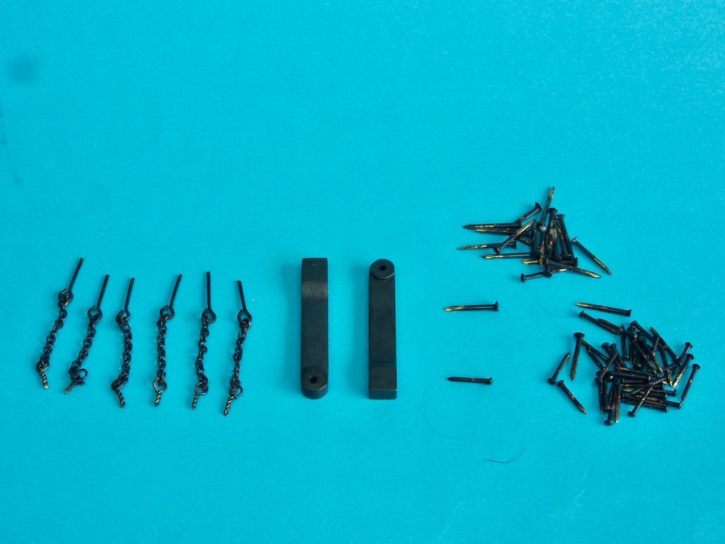
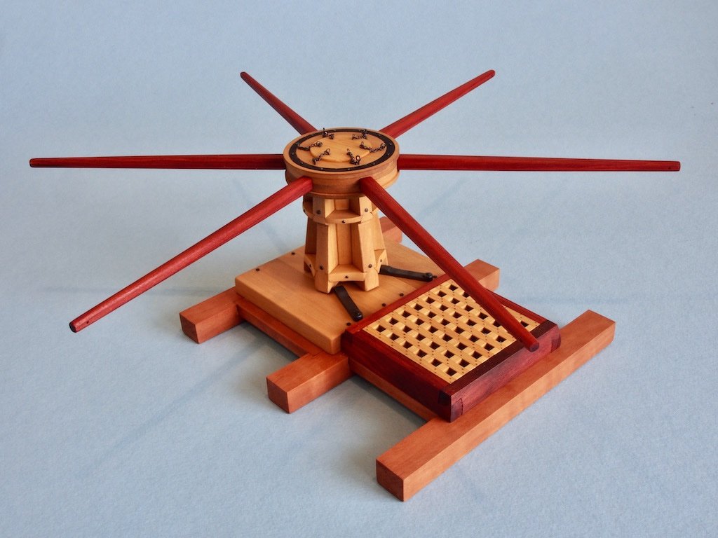
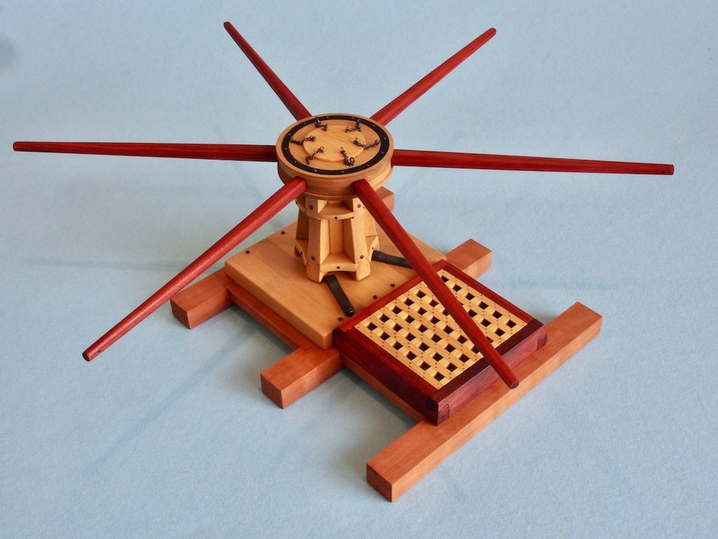
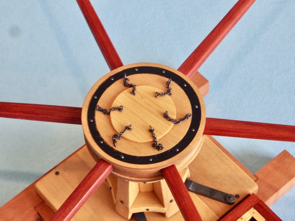
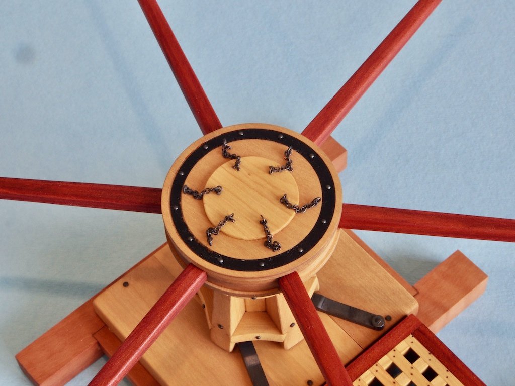
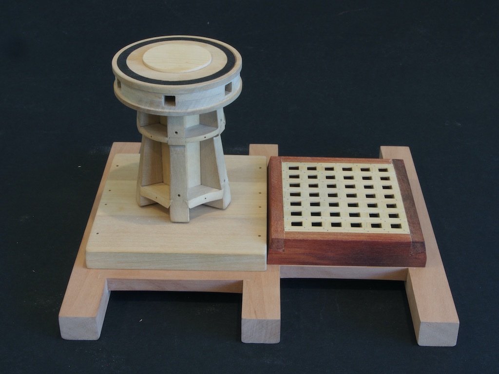
Metal work and Blackening I decided to “cheat” when it came to the bolts and have used two different sizes of brass nails left over from kits various to represent all of the bolt heads. Similarly, left over eye bolts were used for the bar retaining pins, and I found some chain sculling around in the spare parts box as well. The only thing I did make were the eyebolts that secure the bar pin chains to the centre of the drumhead. There have been many discussions on this forum regarding blackening and I have tried various of them over the years. For blackening brass, my go-to product has become Jax Pewter Black, which claims to work with pewter, lead, brass, bronze, copper, tin-lead alloys, and solders. The key to success with this product (for me) has been to NOT dip or soak the parts to be blackened in the solution. Rather, by using a small bristle paint brush, the solution is “rubbed” onto the surface of the part, and then rinsed in distilled water. By using this method, I have found that the blackening does not flake or rub off. Here are all of the metal parts blackened and ready for installation. For the nails/bolts, only the heads needed blackening as the rest won’t be seen. Final Assembly (P/N 1000) All of the wooden parts received two coats of Kunos Oil, wiped on and buffed off immediately. This has left a smooth to the touch finish without too much sheen (more coats = more sheen). With all the metal work blackened, final assembly was a pretty straight forward process. I opted to use 5-min epoxy to secure all of the bolts etc, rather than CA (which I really hate using). So here are some final shots of the completed project: This has been a fun little project that presents more than a few challenges for modellers of all capabilities. I’d like to thank Toni for all her work in making this project available. I'd also like to make a special thanks to Tom (Used to Sail), whose log was a great source of additional information, as well for the occasional PM conversation along the way. Thanks also to all who have stopped by, offered kind comments and/or hit the like button.
- 43 replies
-
- 17
-
-
-
Randy, I have to agree with Ed - more sophisticated tools are more capable (and more expensive) buy aren’t the panacea to all your modelling problems. That said, I’m very biased towards the Sherline lathes and mills - they are a joy to use and do enable you to produce some excellent results - BUT - they also often require a good deal of thought about the process by which you achieve those results. For me, it is often the challenge of how to hold the workpiece for a particular operation that takes the most thinking. I often go searching through logs like Ed’s or Danny Vadas’ looking for ingenious solutions to these problems when they arise. I then try to replicate what they have done. Occasionally, I’ll come up with my own ideas too. Only you can decide whether to return/replace your current tools, Should you decide to do so, my recommendation would be to look at the Sherline range. Yes, they are expensive, but as my dear old Dad often said, “quality is remembered long after price is forgotten”.
- 3,618 replies
-
- 2
-
-
- young america
- clipper
- (and 1 more)
-
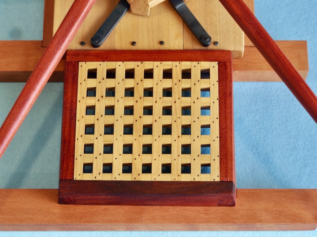
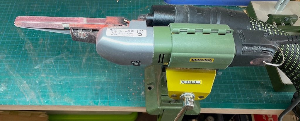
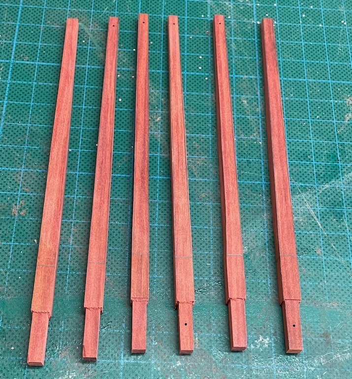
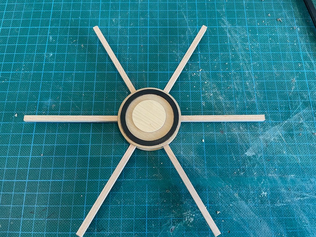
Capstan Bars (P/N 034) The Capstan Bars are relatively simple to make. I am using Red Heart for these (the same timber as used for the hatch coaming). After cutting the blanks to size and finessing with the Byrnes drum sander to ensure all pieces were the same thickness all round, the tenons were cut on the mill and while I was at the mill, drilled the holes for the swifters. I tested some options for cutting the tapers, including a full-size edge sander (not enough control), the tapering jig for the Byrnes saw (could only do two adjacent edges, and even then, the length of the pieces made this very awkward and a little dangerous for my liking). In the end I settled on my Proxxon belt sander. I bought this tool quite a few years ago and have never used it very much at all. It turned out to be ideal for this particular job. It had the added bonus of being able to be hooked up to a vacuum hose, so I brought my Festool shopvac inside (while the Admiral wasn’t looking) and made quick work of the tapers. Final rounding and smoothing was accomplished with a combination of a modellers’ rasp, a soft sanding block, and a sanding sponge – no pics of this stage. All of the parts have now been given a first coat of oil. All that remains now is to blacken and then install the hardware. Final pics once that has been done.
- 43 replies
-
- 11
-
-
Randy, Your lathe is a wood lathe, hence the rest. Ed uses a lathe designed for metal working, hence the “clamp”, which is the tool holder. These are two very different beasts. With wood turning lathes, you hold the tool by hand to work the piece. With metal turning lathes, the tool is usually held in a tool holder, although you can add a wood turning rest if you desire (Sherline for example offers this as an accessory).
-
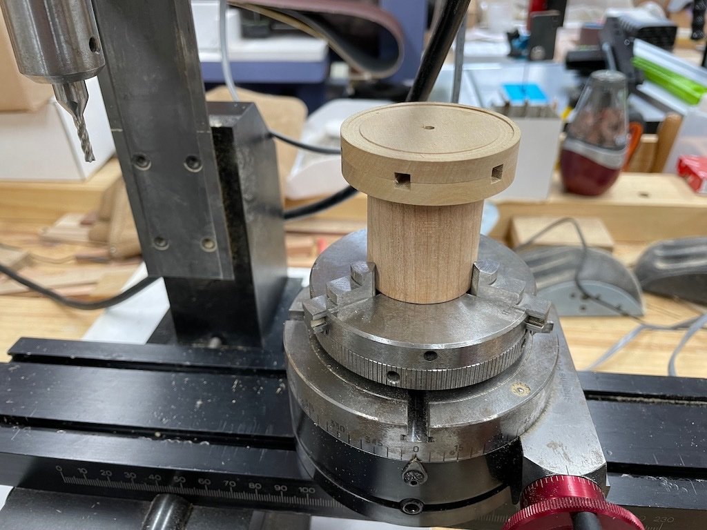
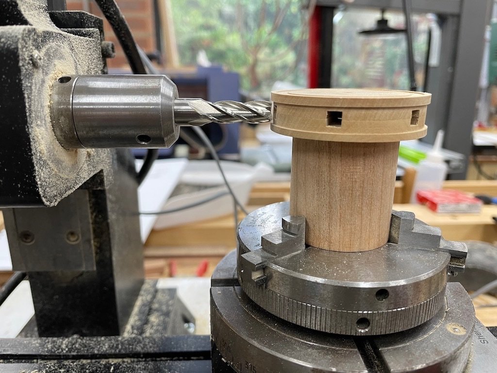
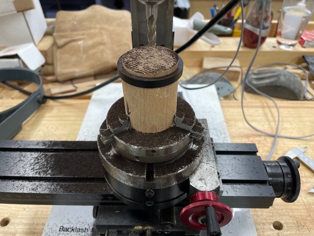
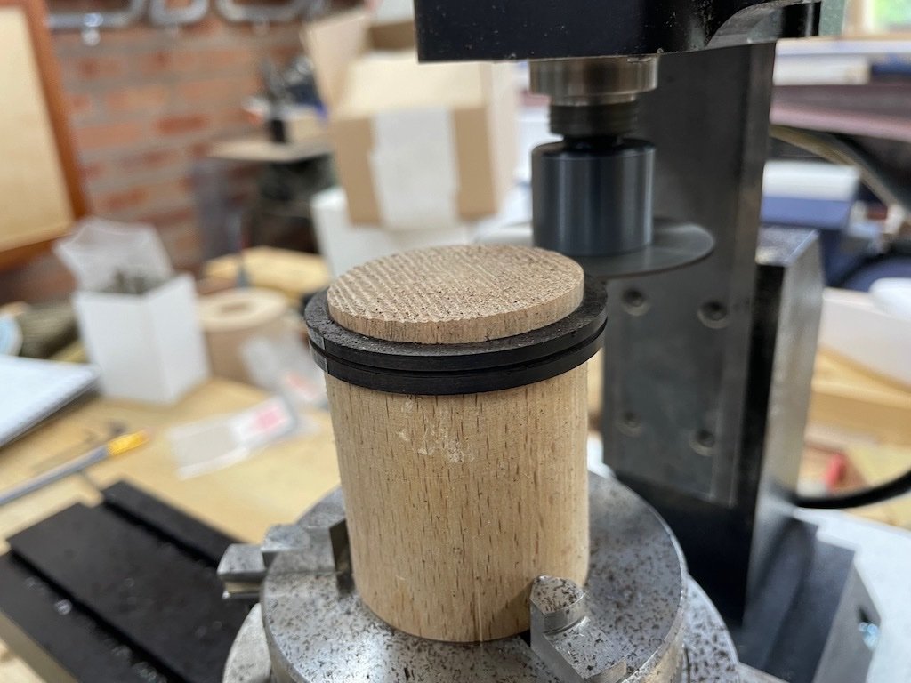
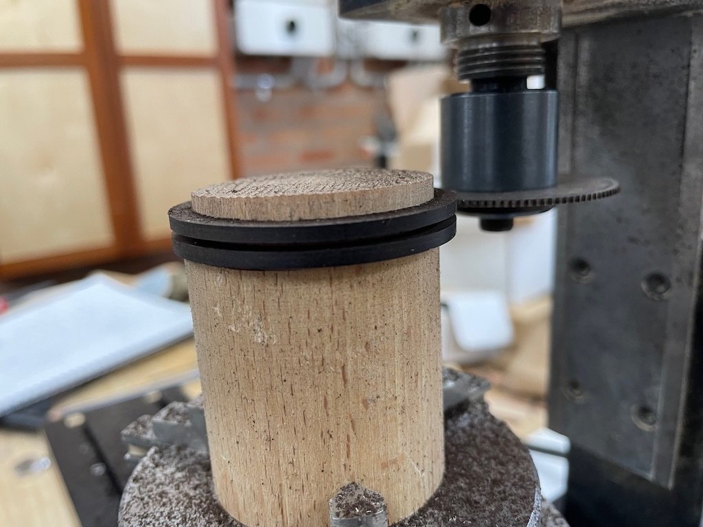
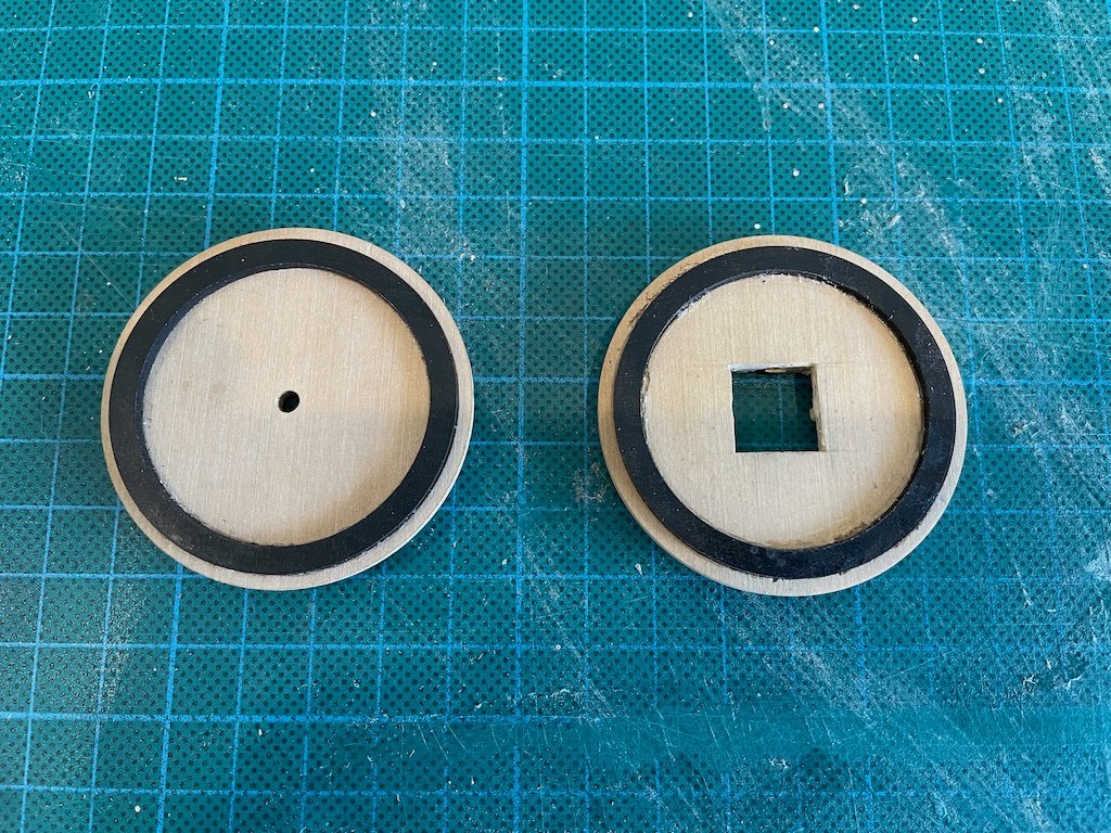
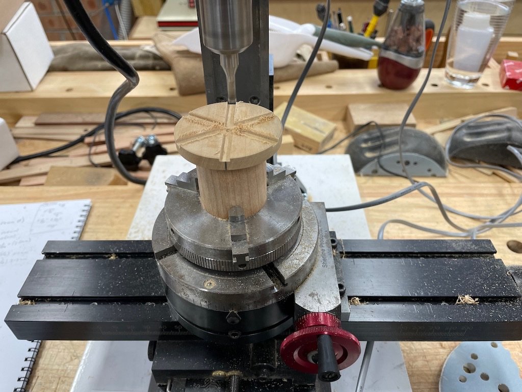
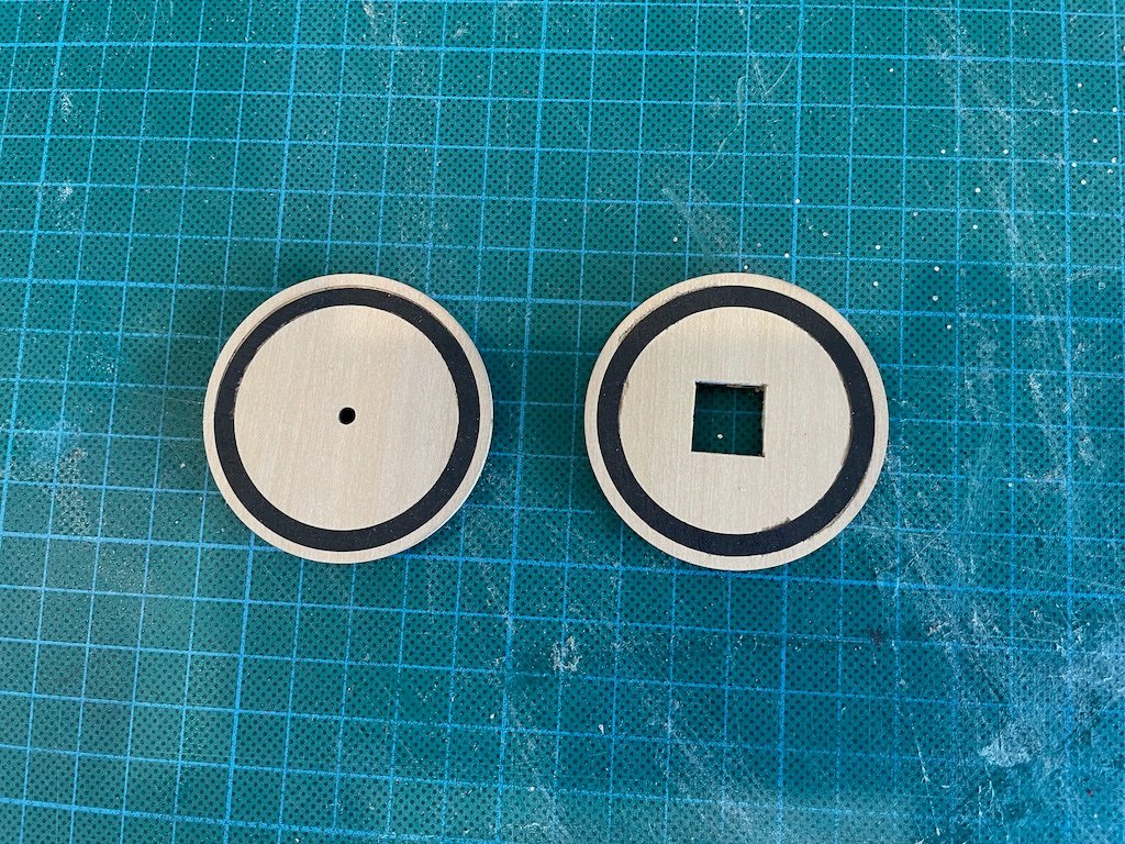
After separating the two halves of the drumhead, they were individually re-mounted to the holding cylinder to have the rebate for the iron ring milled. Each was then de-bonded, flipped, re-glued to the holder and the slots for the capstan bars milled. The drawings show these as 3.25” wide by half that in depth. At scale, that translates to 13/64”. Again, my choice of end mills was limited, so I opted to go with 3/16” (12/64”). Here is a shot of the milling set-up after completing the capstan bar slots, but before cleaning up the “fuzz”. Once both halves had been milled and cleaned up, they were temporarily glued together for the next milling process. Again, my alignment strategy paid off. Here is the drumhead mounted back on the mill – in this shot you can see the rebate for the iron ring milled in the previous process. To mill the rebate in the sides, the mill head was rotated 90-degrees to the horizontal position. It may just be me, but I couldn’t identify from the drawings what the depth of this rebate should be, so I just went with what looked “about right”. Iron Rings (P/N 020) The next task was to make the iron rings. There are two of these required – one each for the upper and lower drumhead. I thought long and hard about whether to use brass or wood for these parts, as well as a process by which to make them. In the end, I opted to go with wood as I had some pieces of ebony that I thought would fit the bill. I began by milling the rough stock to a 6mm thickness. I chose this thickness as I was concerned about very thin pieces self-destructing in the fabrication processes to follow. I then placed blue painters’ tape on one surface and drew two concentric circles to represent the inner and outer edges of the iron rings. Happily, the diameter of the inner circle was 1 5/8”, which just happened to coincide with one of my Forstner drill bits. The centre hole was therefore drilled first, and then the outer diameter was cut to rough shape on the band saw and refined slightly at the disc sander. However, to get the degree of accuracy required, it was necessary to find a way to mount the part on the mill. To achieve this, I took a scrap of thick dowel (actually an old rolling pin), mounted it in the lathe chuck in the mill, and gradually reduced a section at the top until I was able to fit the ring part over it with a snug “push” fit. By having such a snug fit, I was able to complete the milling without having to glue the work piece to the dowel. I gradually reduced the outer diameter with very light cuts (0.1mm at a time) until the part would fit into the pre-milled rebate in the drumhead. Here is a picture of that process under way. A slitting saw was then mounted in the mill and again using light cuts and the rotary table, I was able to cut the 6mm thick piece into two 2.5mm thick rings (I used a 1mm thick slitting saw for stability). Here is a shot of this part of the process underway: And at the end of the process: Here is a shot of the rings test fit into the drumheads: And a test fit with some spacer bars and the Cap (P/N 021) temporarily in place. And here are the drumheads after sanding the iron rings flush: And finally, here is the overall state of play to date. No finish has been applied yet. Some metal work and the capstan bars are all that remain…
- 43 replies
-
- 13
-
-
-
NRG VIRTUAL WORKSHOP - USING THE TABLE SAW
gjdale replied to kurtvd19's topic in NAUTICAL RESEARCH GUILD - News & Information
Kurt - just wondering when this workshop video will be available on the NRG website as a month has now passed and it’s still not there?
