gjdale
-
Posts
4,894 -
Joined
-
Last visited
Content Type
Profiles
Forums
Gallery
Events
Everything posted by gjdale
-
 That’s interesting Wefalck. Given that the instructions for painting these parts called for them to “leather brown”, I’m guessing that they were indeed a stack of leather discs as you noted. When Ken Foran (Xken here at MSW) designed this model, he had full access to the preserved original. I’m pretty sure his design is faithful to that original.
 -
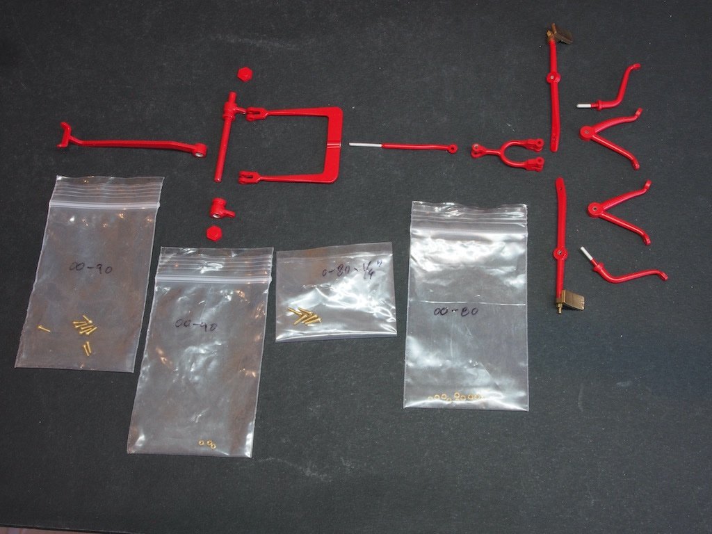
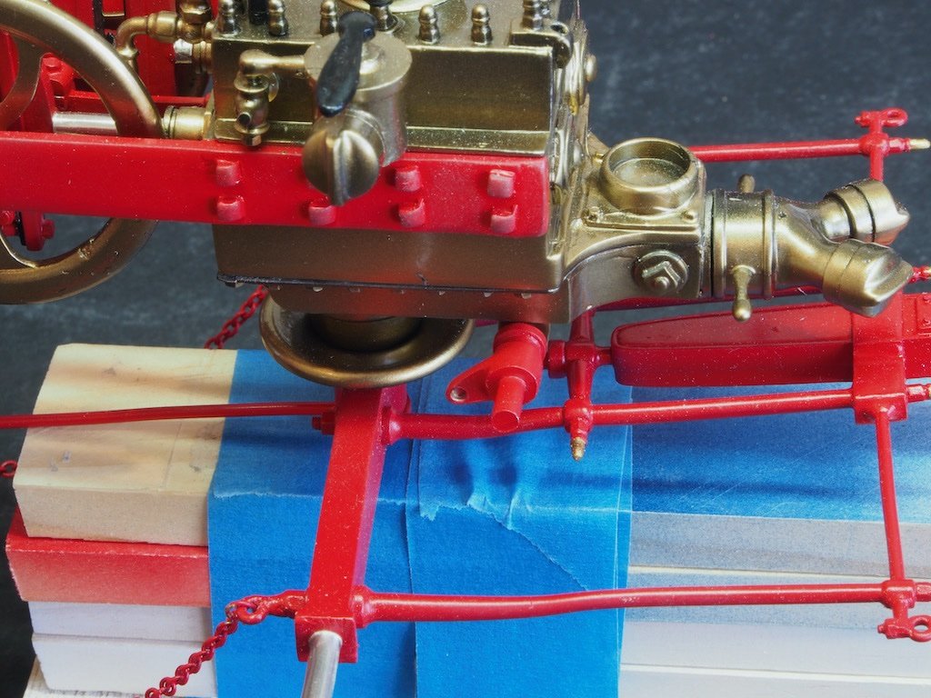
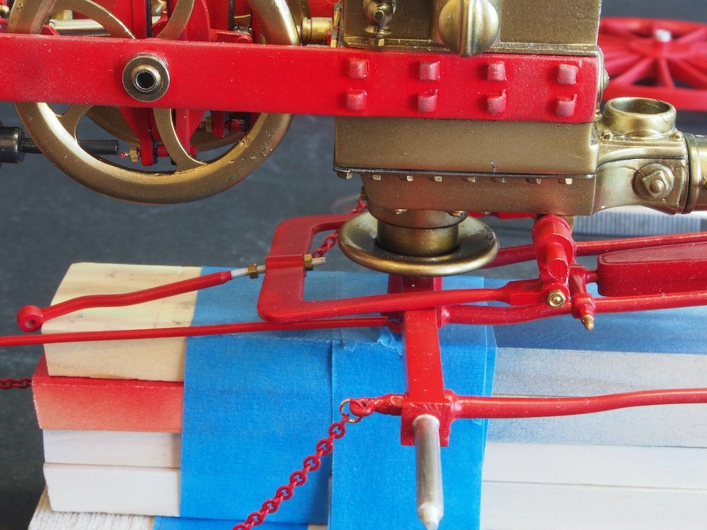
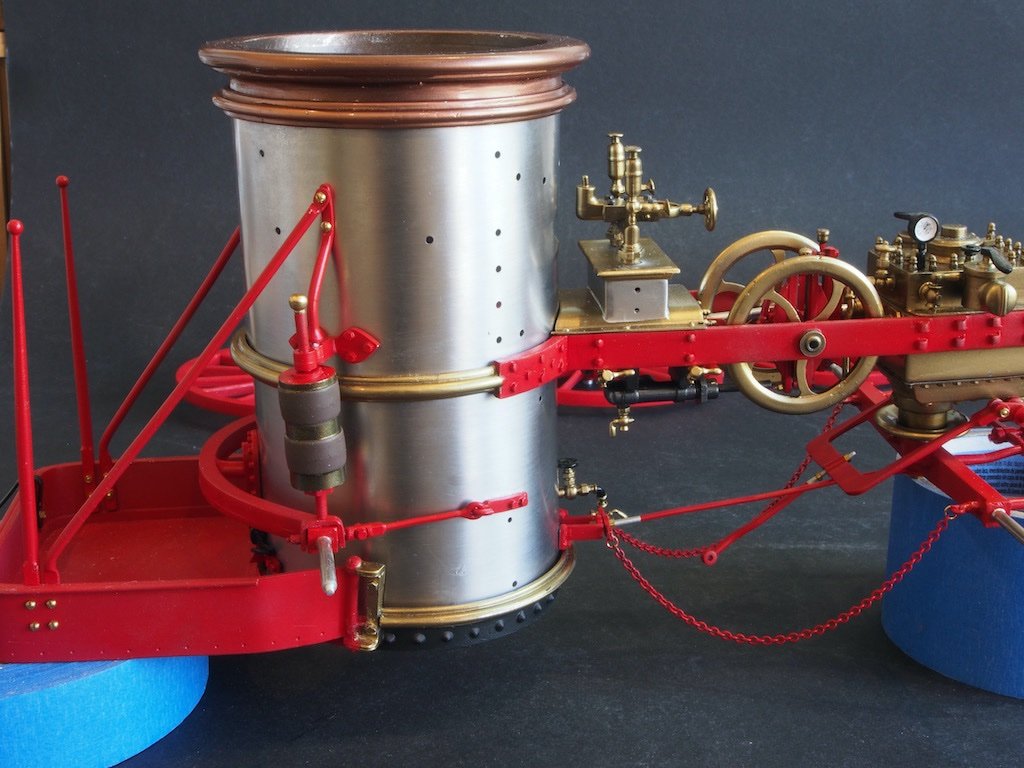
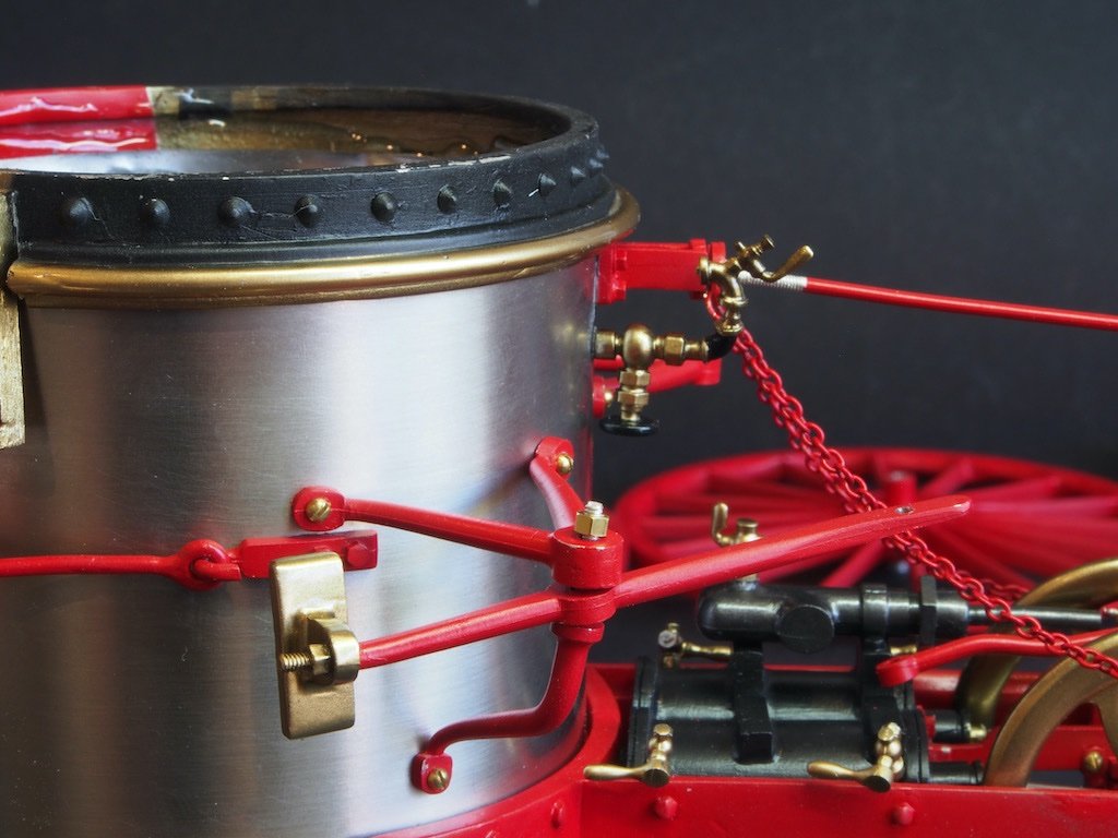
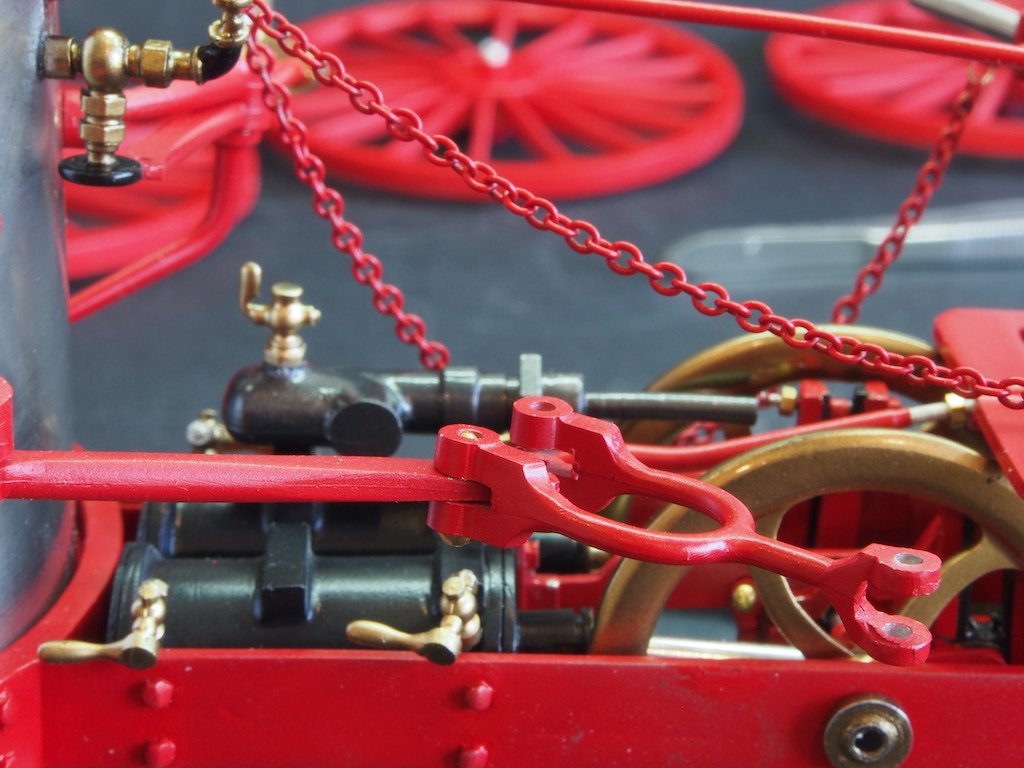
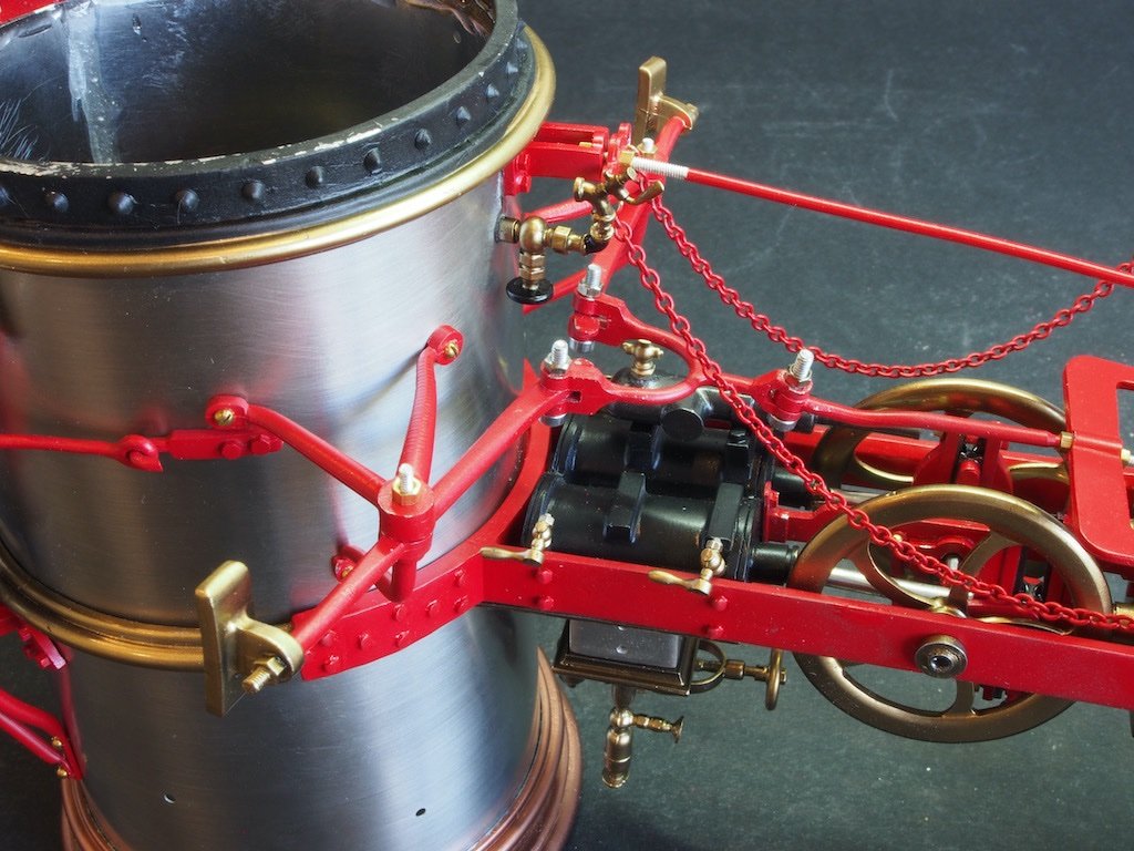
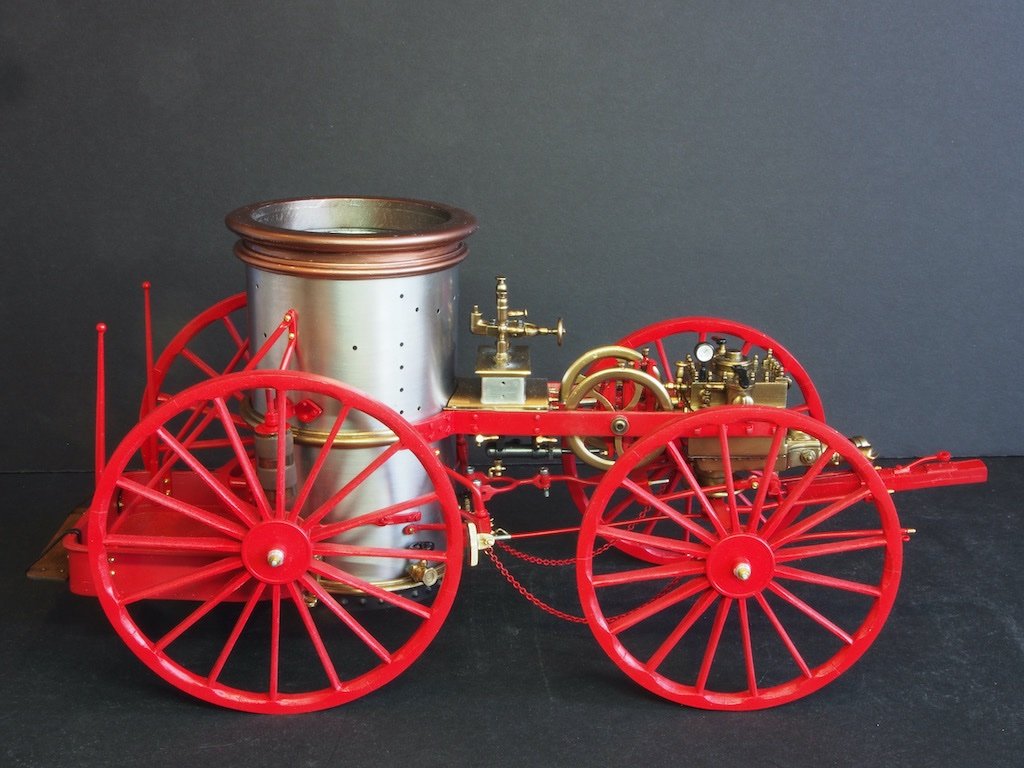
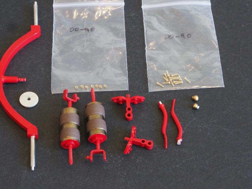
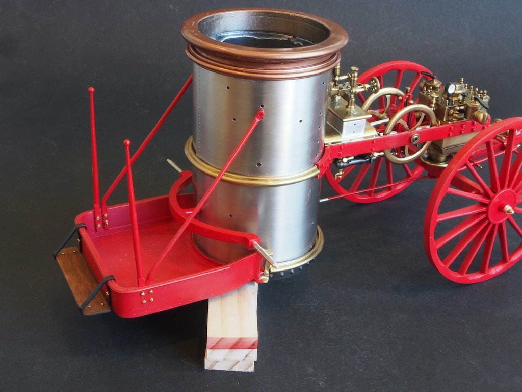
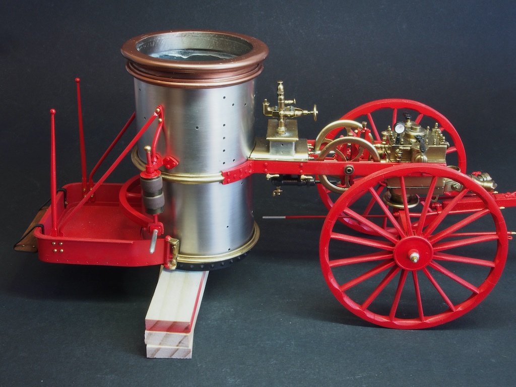
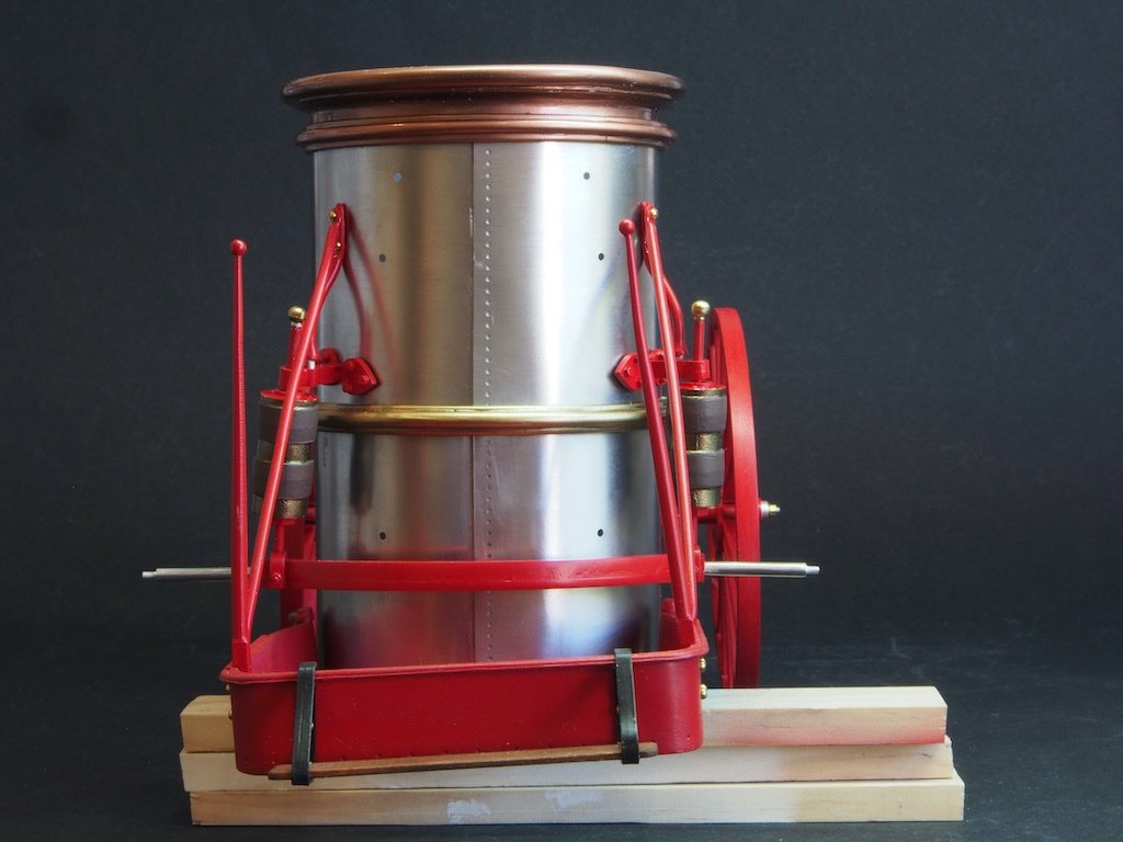
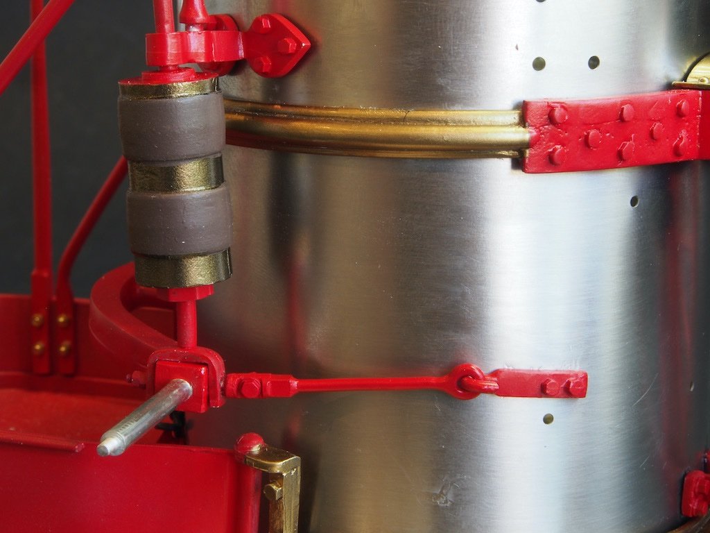
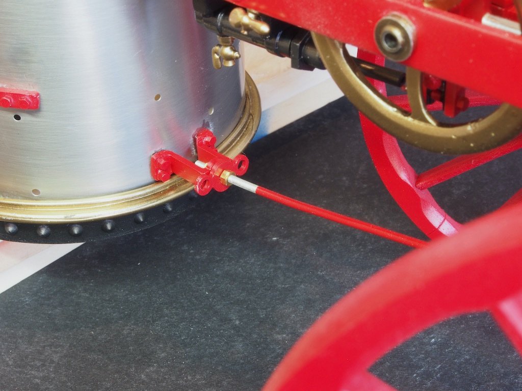
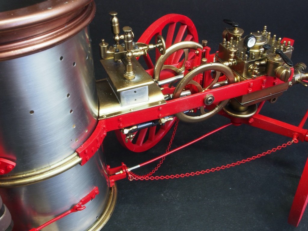
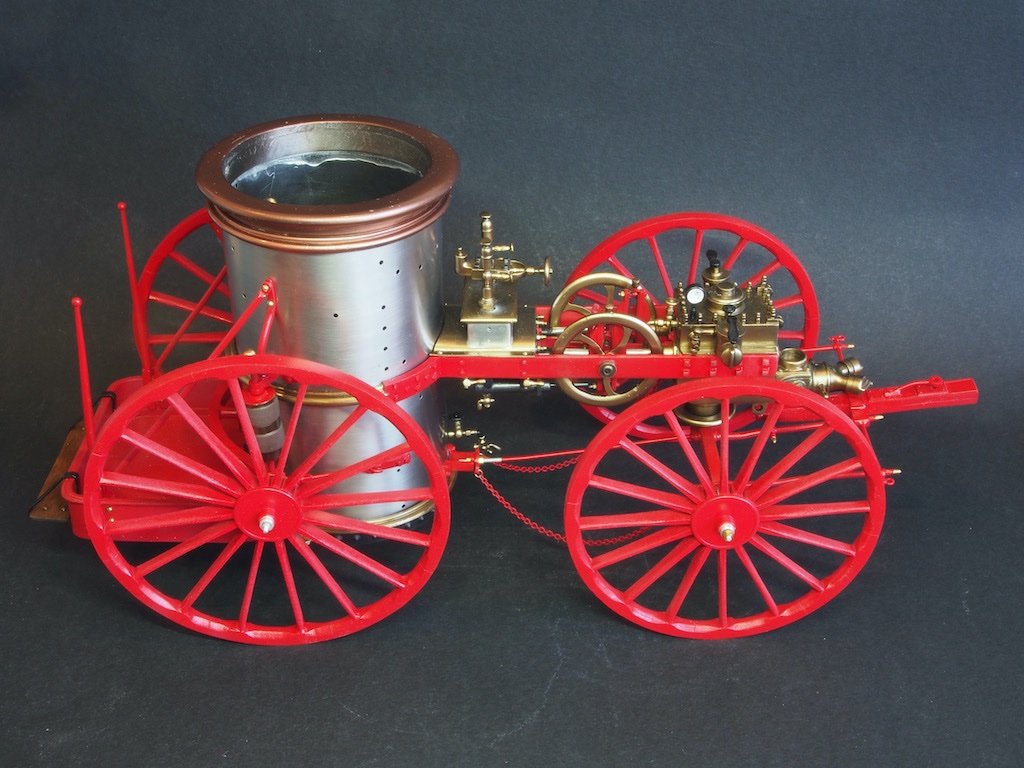
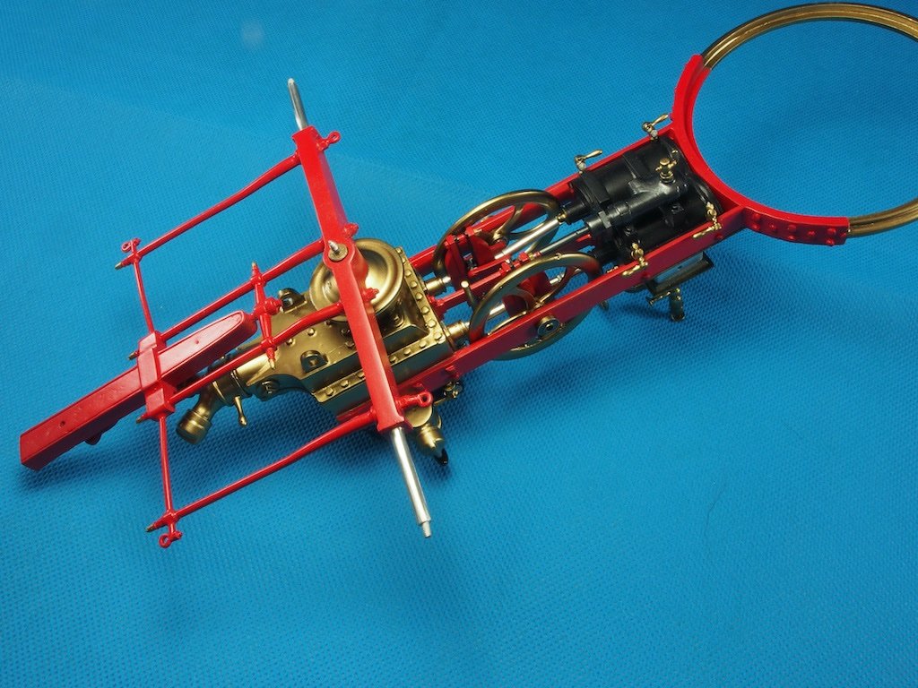
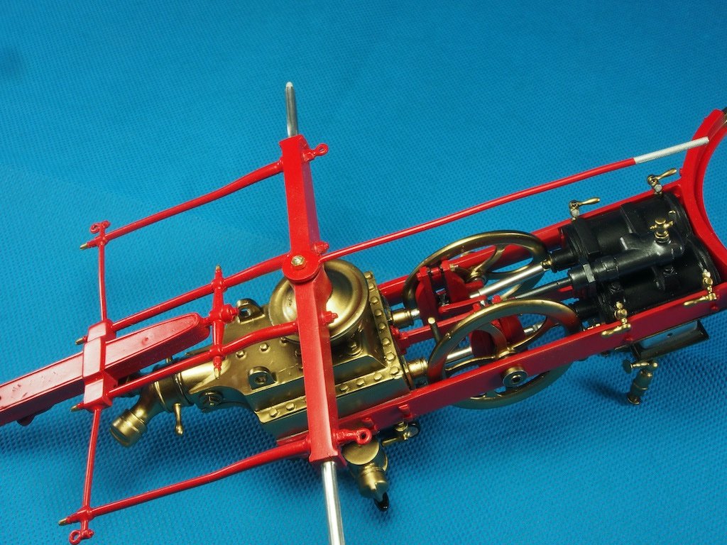
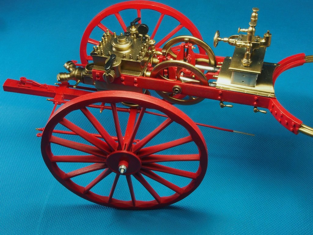
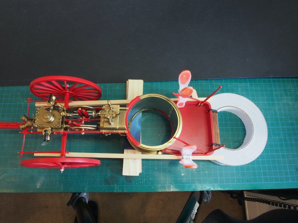
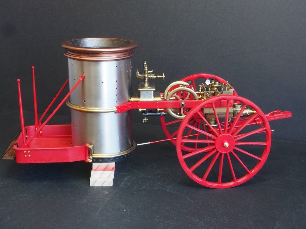
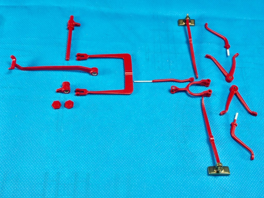
A successful day at the “Fire Station” today, although not without it’s challenges. The Brake System The next step is the installation of the Brake System. Here are all the component parts: We start by removing the wheels, propping up the main frame and front axle, and inserting the Brake Crossover Bar (second from left in the above picture) through the holes in the bottom of the Water Box. These were test fitted when the parts were being painted, so no unwelcome surprises here. We then take connect the Brake U-link to the Brake Link using a pair of 0-80 nuts on the threaded end of the Brake Link. These will be used later on to adjust the length of the Brake Link. The U-link is then connected to the Brake Crossover Bar on the right-hand side of the vehicle using a 0-80 x 1/4” bolt from the inside and securing with a 0-80 nut on the outside. Then we add the Crossover Bar Link on the left-hand side of the Crossover Bar and repeat the connection to the U-Link. Not particularly difficult, though something of a dexterity test. We now need to install the Brake Lever Pivot Arms, Pivot Arm Braces, and the Brake Lever Arms. The Pivot Arms and Braces form a triangle that is bolted to the boiler wall using 00-90 bolts and nuts. They are positioned toward the bottom of the boiler. In this photo, you can see the length of reach required inside the boiler to be able to attach the nuts. Here I decided to depart from the instructions and carefully inverted the entire model so that it sat on the boiler cap ring and was supported at the front end of the water box. This allowed me to access the bolts from the underneath of the boiler. I retained this position for the remainder of the installation. Here is the triangular bracing in place, along with the Brake Lever Arm. Once both Brake Lever Arm assemblies had been attached, we are instructed to add the Brake U-connector to join both Brake Lever Arms to the Brake Link using 0-80 x 1/4" Bolts and Nuts. One problem with that…..the 1/4" bolts are not long enough for the job, as seen in this photo. I had a dig through my leftover bits and pieces from my Pocher car build and found some suitable alternatives. They were slighter larger in diameter at 2mm, so I had to re-drill all the holes, which in turn meant dis-assembling some of what I’d already assembled. Here is the result: While the bolts may now be a little too long, I’m not going to worry about cutting them shorter as they can’t be seen that well anyway. At this point, the misalignment issues discovered earlier came back to play and a little judicious bending of the brake arm assemblies was required. The Main Drain was also inserted while the wheels were off. The pre-drilled hole in the boiler wall was a little too low for it to sit correctly, so I elongated the hole somewhat with a small needle file until I could get it to sit correctly. The wheels were put on, at which point we find another error in the Bill of Parts. The wheels are held on with 1-72 nuts. The parts list indicates that 8 of these are supplied and indeed that is what was in the kit. Only problem is, 9 are required to build the model. By happy coincidence, the replacement nuts I used for the U-connector were just the right size to fit on the axle stub I had previously broken and re-glued. The remaining provided nuts all went on to the cast threads without issue. Here is an overall shot of where we are at today:

- 138 replies
-
- 18
-

-

-
Love the home-made tools! Great addition and well done.
-
Happy to be of service my friend! 😉 And a belated Happy 75th
-
Nice progress Mark - must feel good to reach that particular milestone.
- 505 replies
-
- 5
-
-
- vanguard models
- Sphinx
- (and 1 more)
-
That’s my intent Mark. Not so much to bleat, but to provide some constructive feedback to help them fix the errors. That’s one reason I’m putting them in my log as I go - will make it easier to pull together at the end.
-
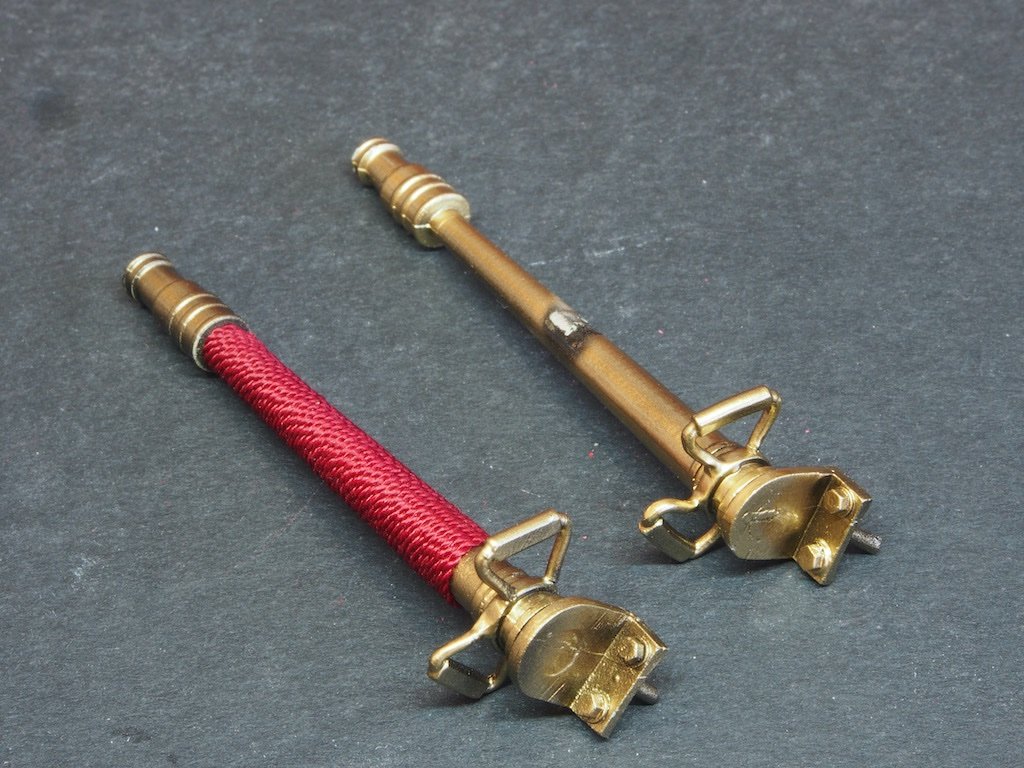
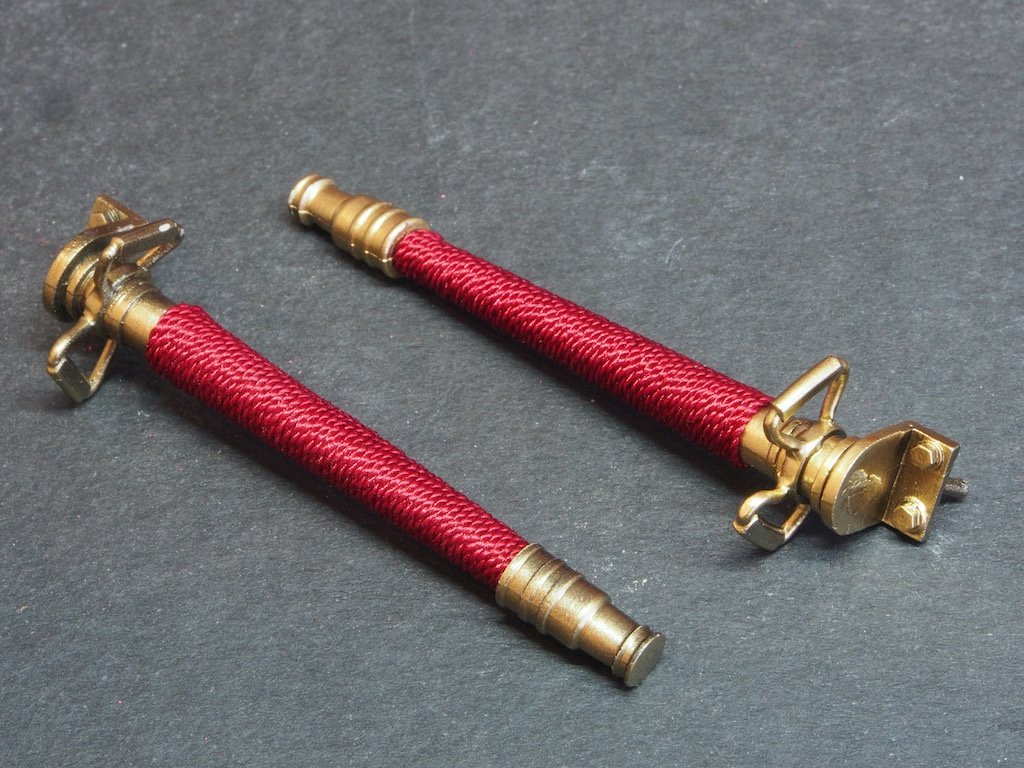
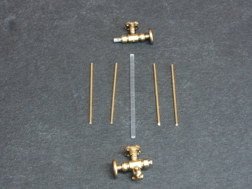
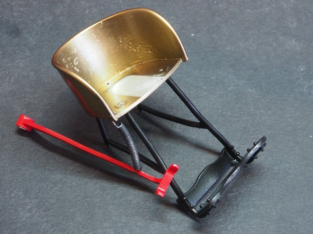
Thanks again for all the input (and also for the "likes" following along). A somewhat frustrating day in the workshop today. What the…? Prior to tackling the Brake System, the instructions call for three small jobs to be done: finishing the Hoze Nozzles, constructing the Boiler Water Level Sight Gauge, and making the Brake Spring. All three should be simple, straight forward tasks. All three had issues… Hose Nozzles The instructions call for wrapping the Hose Nozzles in the rather nice red thread provided using a Common Whipping. We are advised to take a 36” piece of the thread for each Nozzle to do this. I cut the thread in half and noted that each half was very slightly longer than the prescribed 36”. Good, I thought… Then I discovered that no matter how frugal I was in allowing for the ends and the loop, there was no way that a 36” piece of thread was going to cover the entire Hose Nozzle. After some experimentation and a lot of cursing, I managed to make it cover all bar about 3-4mm at the handle end. Why Model Expo couldn’t have made the supplied thread a couple of inches longer is beyond me. It is not something that I can duck out to a local store to replace either. Very annoyed by this totally unnecessary error. Anyway, here is a picture of in progress showing one Nozzle wrapped and the other pre-wrapping. And here they are completed. You can see in the photo where the wrapping stops short of the handles. It should go all the way to the handles per the instructions and included photos. Boiler Water Level Sight Gauge The Boiler Water Level Sight Gauge is made of a top and bottom cast part, four connecting brass rods and a clear plastic rod. Here are the parts laid out (and yes, one of the top/bottom parts is facing the wrong way). It’s quite a clever construction design, but … The issue here is the diameter of the clear plastic rod. The parts list in the written instructions for this component call for a 3/32” diameter rod. The separate drawing sheet for the clear plastic components calls it out as 0.0625” (1/16”). The part that is provided is 1/16”. The recesses in the cast components are sized to accept 3/32” (as confirmed by test fitting a piece of 3/32” brass rod I had on hand). Really guys? What happened to proof reading and quality control? The most frustrating thing about this error is that I don’t have stocks of clear plastic rod to hand. Using the provided 1/16” rod is a non-starter as it will both look wrong and be difficult to actually construct. I have managed to track some down of the right size through one of my ‘go-to’ Hobby Stores, but it is costing me $10 for a pack of 5 rods, each of 250 mm length (I need one piece 25 mm in length), and then it’s costing me another $14 in postage and a wait of about a week or so. Again, totally unnecessary and very frustrating. Brake Spring The instructions call for you to make the Brake Spring from the provided wire. A simple enough task – what could possibly go wrong? Well, first up, the instructions for this appear in two places in the instruction manual – once on pg 25 and again on pg 42. And these instructions are actually different to each other! On pg 25 it calls for using a piece of 28g brass wire and on pg 42 it calls for using 0.020 brass wire. Well, I looked up some tables and 28g is 0.0126”, while 0.020” is 24g. What is provided in the kit is 0.015” which is equates to somewhere between 26g and 27g. It would appear that the instructions were revised at one stage and one version of this section should have been removed but wasn’t. At least they could have provided the right size wire for one set of instructions instead of neither! At least this was an easy fix. The kit provided wire felt a little too thin for the purpose, so I dug through my stash and found some 24g Copper Wire. The advantage of using the Copper Wire is that instead of painting it black, I was able to chemically blacken it with Liver of Sulphur. The technique is dead easy – just insert a 1/16” drill bit in a pin vise with the smooth end sticking our about 3/4” and then wrap the wire around the drill bit. Form a couple of “U” hooks on the end and job done. Here is the result, test fitted between the Seat and the Brake Pedal Arm. Okay – now I’m ready to tackle the Brake Sysem…
- 138 replies
-
- 12
-
-
-
Hey Bob, any progress on this beauty lately? Or did you start another build that you are keeping from us?
-
Thanks for the input and suggestions Ron and Egilman. Noting Egilman’s comment on thread chasing, I think Ron’s suggestion is the safest way to go. I think then that I won’t mess about. If the nuts don’t go on nice and easily (as they did on one side of the front axle), I’ll drill out the nuts and glue them on. Once they are on, they won’t be under any strain, so a spot of CA should be fine to hold them. Thanks again for the input everyone - one of the many things I love about this forum! 😊
-
Thanks Wefalck. That’s an interesting point you make about ‘joggling’ the joint - I think I understand what you mean and it makes a lot of sense. It would certainly address the issue of alignment. However, the instructions (including photos) say to do it the way I have. Would be really interesting to try though…. Perhaps the next person to tackle this kit can try that approach - I’d certainly love to see it done that way. I’ve been wondering about the possibility of chasing the threads on the cast parts, but I’m not convinced the metal would stand up to even that amount of torsional force. I’ll dig around in the tool chest this week and see if I have a 00-90 die and if so, might give it a try. What could possibly go wrong? Worst case is I break the thread just the same as if I just try to put the nut on without first chasing it wth the die.
-
Nice progress Sjors - Anja must be really cracking the whip on you at this speed!
-
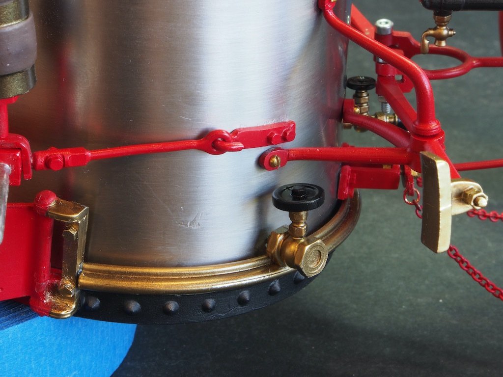
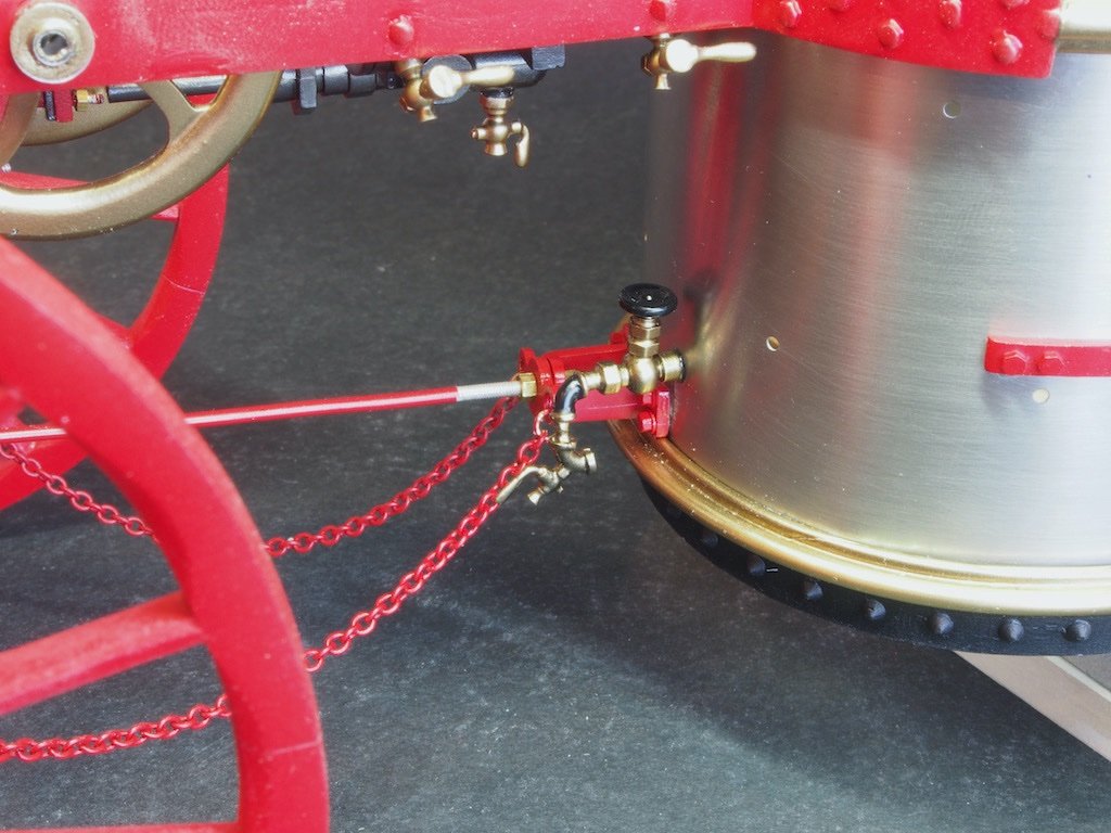
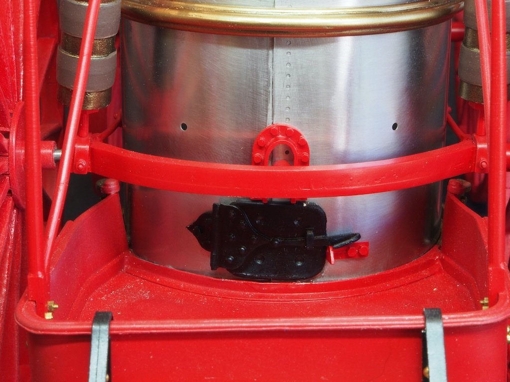
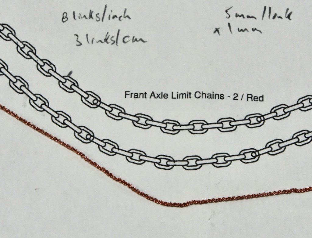
Rear Axle Next up is the gathering of parts for assembly of the Rear Axle. This includes the previously painted parts plus some 00-90 nuts and bolts. First up, the Rear Axle is mounted with it’s support shaft inserted through the hole in the lower boiler wall and the Rear Axle Lock (the unpainted disc in the above picture) inserted from inside the boiler and glued in place. Not too difficult, except being able to reach down inside the boiler from above to place the Lock. The next step is fitting the Shock Absorbers and their vertical and horizontal braces, as well as the Coal Bin Braces. While the horizontal braces only have a locating pin to place in the respective hole in the boiler wall, both the vertical braces and the coal bin braces are attached with 00-90 nuts and bolts, with the nuts being secured on the inside of the boiler. While the dexterity required to attach these little critters is quite challenging in itself, the real problem is a matter of alignment. Even though I had been meticulous in my forming of and placement of the boiler walls, I found that things just wouldn’t align quite properly. I can only conclude that either the boiler walls weren’t pre drilled in the correct place, or the design did not allow for the additional thickness of the boiler walls where they overlap, which in turn reduces the outer diameter of the boiler in order for it to fit within the boiler and main frame rings. Whatever the cause (and I don’t think it’s operator error), the result is that the shock absorbers don’t sit quite vertically, and in order to make the coal bin braces align with the respective holes in the boiler wall, a significant twist is imparted to the coal bin floor. This photo shows the extent of that twist. The good news is that the model is normally viewed from the side, so the twist isn’t really evident from that angle, and the rear wheels obscure the shock absorbers to the extent that their misalignment becomes largely unnoticeable as well. Nevertheless, it was disappointing to have come this far in the build, only to encounter this issue. Having decided that there was absolutely nothing I could do to correct this issue, I pushed on. Next up was adding the Rear Axle Links and Hooks. These are simply attached with CA glue to the Shock Absorber bracket and Boiler wall. Front Axle Brace The Front Axle Brace now gets attached to the Front Boiler Wall. This is achieved by placing a 1-72 nut on the threaded end of the Brace, either side of the Chain Attachment Bracket and the Brace Plate. The two nuts are then used to adjust the ‘length’ of the brace such that the Attachment Bracket sits flush against the Boiler wall, where it is glued in place with CA glue. Chains Two lengths of Chain were used to limit the travel of front axle and prevent the rim hitting the main frame. The instructions say to cut two lengths of Chain 4 7/8” (98mm) long. Ummmm 98mm is 3 7/8”…. So which is it? As it turns out, neither measurement is correct. I started with the longer length (4 7/8”) and after placing the first one could see that it was way too long. I adjusted it visually so that the chain was doing what it was supposed to do, and then cut it to length – which turned out to be 4 1/8”. The jump rings still need a little touch up of the red paint here. While I was in that vicinity, I decided to add the Centre Pressure Release Valve as I could not find any further reference to it in the instructions. It took me a while to find it on the drawings too. I could just make it out in some other reference photos later in the instructions, but only as an ‘incidental’ to what the photo was illustrating. As it’s quite a difficult place to get to, I figured installing it now was probably a smart move. Rear Wheels The Rear Wheels are slipped temporarily in place on the Rear Axle. As these will be removed several times yet, I decided to heed the instructions and not try to fit the securing nuts for fear of breaking another axle. The Rear Axle Guide, Boiler Coal Door and Door Latch were added a little earlier, but I forgot to take a picture at the time. Here they are in place too: A little diversion now while I attend to the wrappings for the Hose Nozzles and also make up the Boiler Water Level Sight Gauge, before returning to my most dreaded task - installing the Brake System...
- 138 replies
-
- 16
-
-
Thanks Mark. It's not the nuts and bolts that are Britannia metal (they are brass) - it's the threads on the axles and shafts that are the problematic Britannia metal.
-
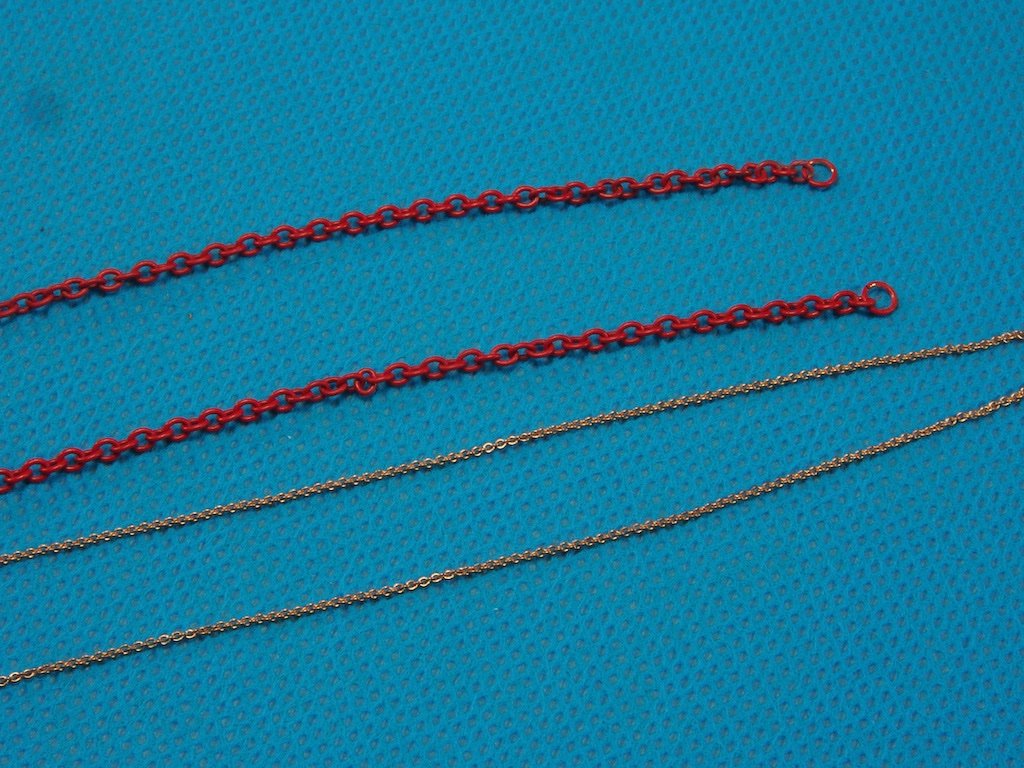
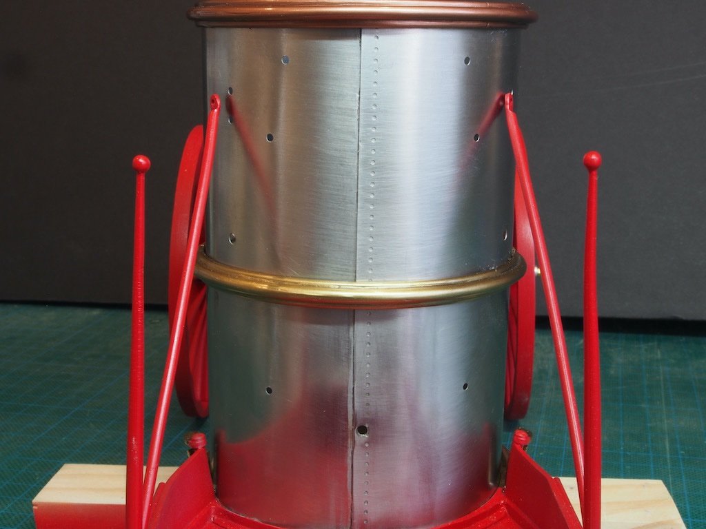
Assembly Commences… As it happens, the extra Red paint turned up the day after my last post, along with the replacement chain I had ordered. The wheel painting was then able to be completed. I gave them all a coat of Alclad Klear Kote Light Sheen and a light touch with a 1200 grit sanding stick. The hubcaps were all test fitted for a nice press fit. I also painted the new chain while I was at it. I’m very happy with the size of this chain – it looks “about right” when overlaid on the 1:1 scale drawings. Here it is alongside the kit-supplied chain for comparison. And with that, all painting (other than touch-ups) is completed. Assembly can now commence. Front Axle Assembly The first step in assembly is the installation of the front axle. To this, the previously completed main frame sub-assembly was carefully turned upside down and the Front Axle placed over the Pivot Shaft. The Front Axle Brace is then slipped into place and secured with a 1-72 nut. I worry every time I have to place a nut onto a thread on a cast part. This Britannia metal is so soft that the slightest torsion will cause the part to break as I was about to find out – again… The Front Wheels are then temporarily installed. As the Front Wheels will need to be removed later to add the Brake Linkage, the instructions simply advise to be careful that they don’t inadvertently come off and cause damage. I thought that was a recipe for disaster, so decided to temporarily add the retaining washers and 1-72 nuts onto the threaded ends. One side went on beautifully. The other proved my point about the softness of the Britannia metal. I was being as gentle as I could possibly be, but the thread was not cast perfectly and with just a slight amount of pressure, the thread broke. I have re-attached the broken part for now with CA glue, but will need to find a permanent solution once the Brake Linkage has been installed. Boiler Walls The lower boiler wall – formed way back as the very first stage of construction – is now attached to the Coal Bin. Alignment is critical here and the instructions guide you to align the centre of the rear axle support shaft hole in the boiler wall with the centre rivet in the Coal Bin floor joint. The Boiler Top Ring is temporarily added as a sizing fixture and brace. Once satisfied with the alignment, we are instructed to glue the boiler wall in place from the inside using CA glue and once set, to reinforce with 5-minute epoxy, also adding epoxy to the vertical joint in the boiler wall as further reinforcement for that joint. All I can say is, easier said than done! The boiler wall sits on a very narrow ledge and it is very difficult to get glue in place. I can see that this will be even more tricky once we get to attach the top of the lower boiler wall to the main frame… At this point, the hole for the Rear Axle Support Shaft has to be re-drilled through the inner wall (where the two ends of the boiler wall overlap. That also proved quite tricky and resulted in me having to subsequently re-attach the boiler wall to to the Coal Bin… The instructions stress the importance of aligning correctly the Coal Bin and the Main Frame, ensuring that the sides of each are parallel. The suggested method is to temporarily clamp some scrap pieces of stock to the sides of the coal bin to assist the visual alignment. Great in theory, but neglects the fact that the sides of the Coal Bin are not perpendicular to the axis of the main frame. In this overhead shot, you can clearly see the taper from rear to front. Nevertheless, the same result can be achieved by “middling” the gaps and trying to ensure an even taper on both sides. Once that is achieved, the coal bin is first glued with CA to the Main Frame Boiler Ring, and then followed up with 5-min Epoxy. This proved again to be quite a tricky process as one needs to reach over and up under the upper rim to place the glue on the inside of the joint. Fortunately, the insides of the boiler will never be seen, so neatness is not a requirement! Once the Epoxy had set, it was time to add the upper boiler. Again, the instructions stress the importance of aligning the two boiler walls by aligning the line of rivets at the join in the walls. The Boiler Top Ring is again used as a steadying and forming aid to maintain the shape as the lower edge is fitted into the Main Frame ring. Here you can see the upper boiler in place and aligned with the lower boiler. You can also see in this photo the hole for the Rear Axle Support shaft after re-drilling in the previous step. Once again, both top and bottom joints are glued with CA and followed up with 5-min Epoxy. This was even trickier than gluing the lower boiler and the use of long bamboo skewers proved to be an excellent choice of gluing aid. Once set, the instructions ask you to dry fit and then glue in place the Boiler Cap Ring. Once I dry-fitted mine, the fit was so snug that getting it out again to place some glue was proving to be problematic. In the end, I decided that the fit was so snug, that glue wasn’t going to be necessary. Here is the result. More to follow shortly....
- 138 replies
-
- 15
-
-
-
Rotary tool recommendations, preferences
gjdale replied to Steve116's topic in Modeling tools and Workshop Equipment
HSS = High Speed Steel -
Great to see you and your lovely model back Patrick. Sorry to hear of the health issues but glad you’ve made it back to the bench.
-
I believe the Birthday fairy will be bringing me one of these next month, so I’ll follow along with interest. 😊
-
Nice work Alan. For painting that size of hull, you'd be better off with a mini HVLP spray gun. The Iwata LPH-80 would be a good choice, although you will need a compressor that can provide enough air flow - your typical hobby airbrush compressor won't, but your average garage/workshop compressor will. I have the LPH80-082G, which has a 0.8mm needle/nozzle and it requires 1.8 cfm airflow. It's wonderful to use too!
- 460 replies
-
- 5
-
-
- Finished
- Flower-class
- (and 1 more)
-
Thank you Bob - that’s very kind of you.
-
Congratulations on completing a fine build Sea Hoss. You can be justifiably proud of her!
- 101 replies
-
- 1
-
-
- emma c berry
- model shipways
- (and 1 more)
-
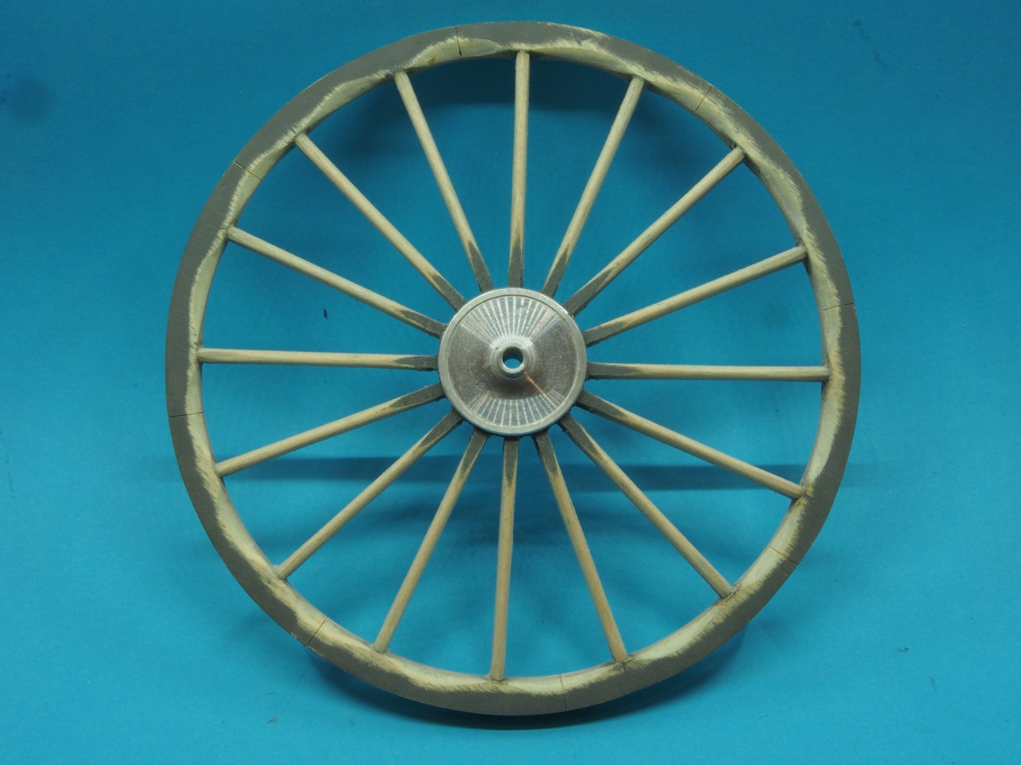
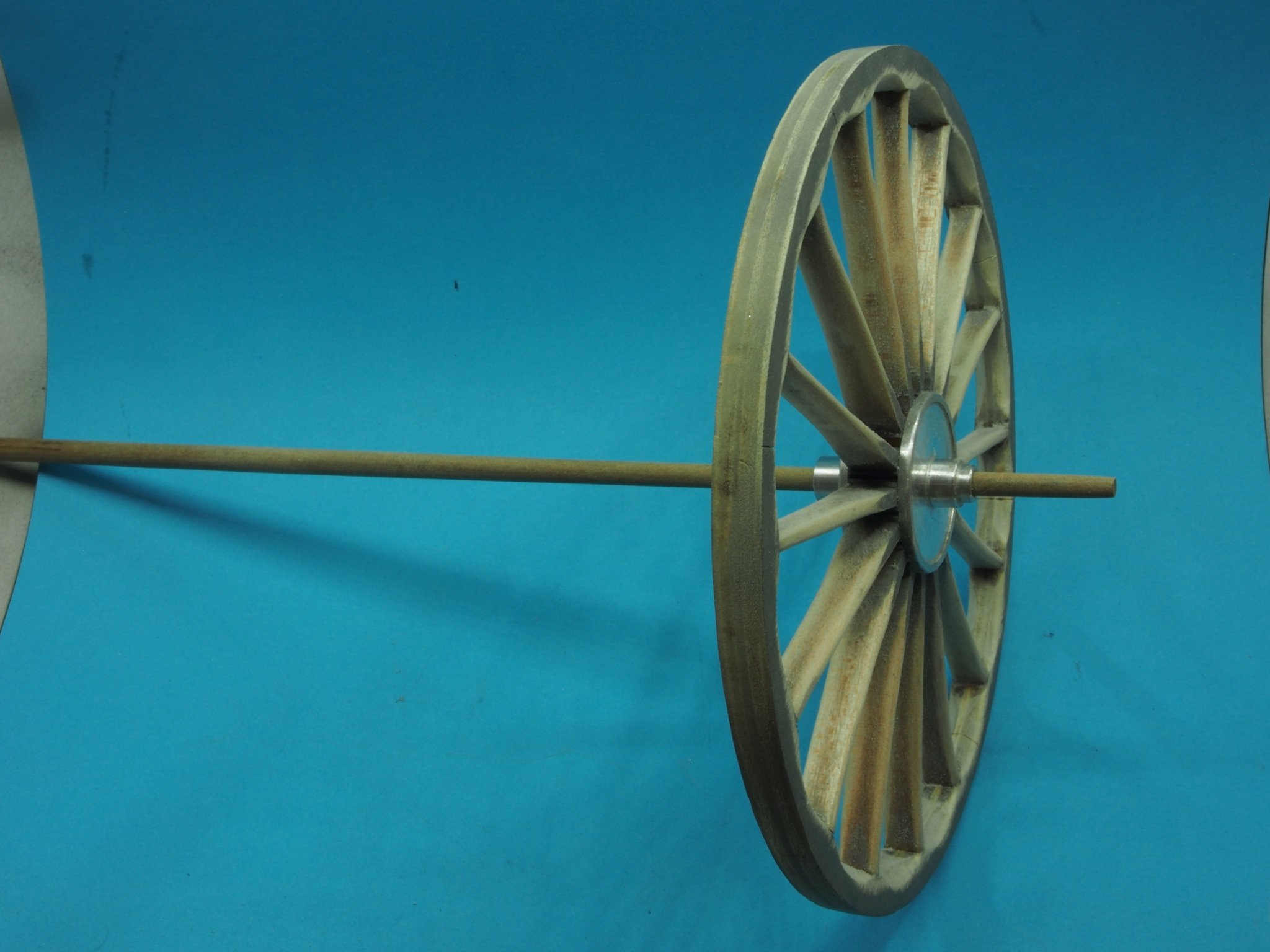
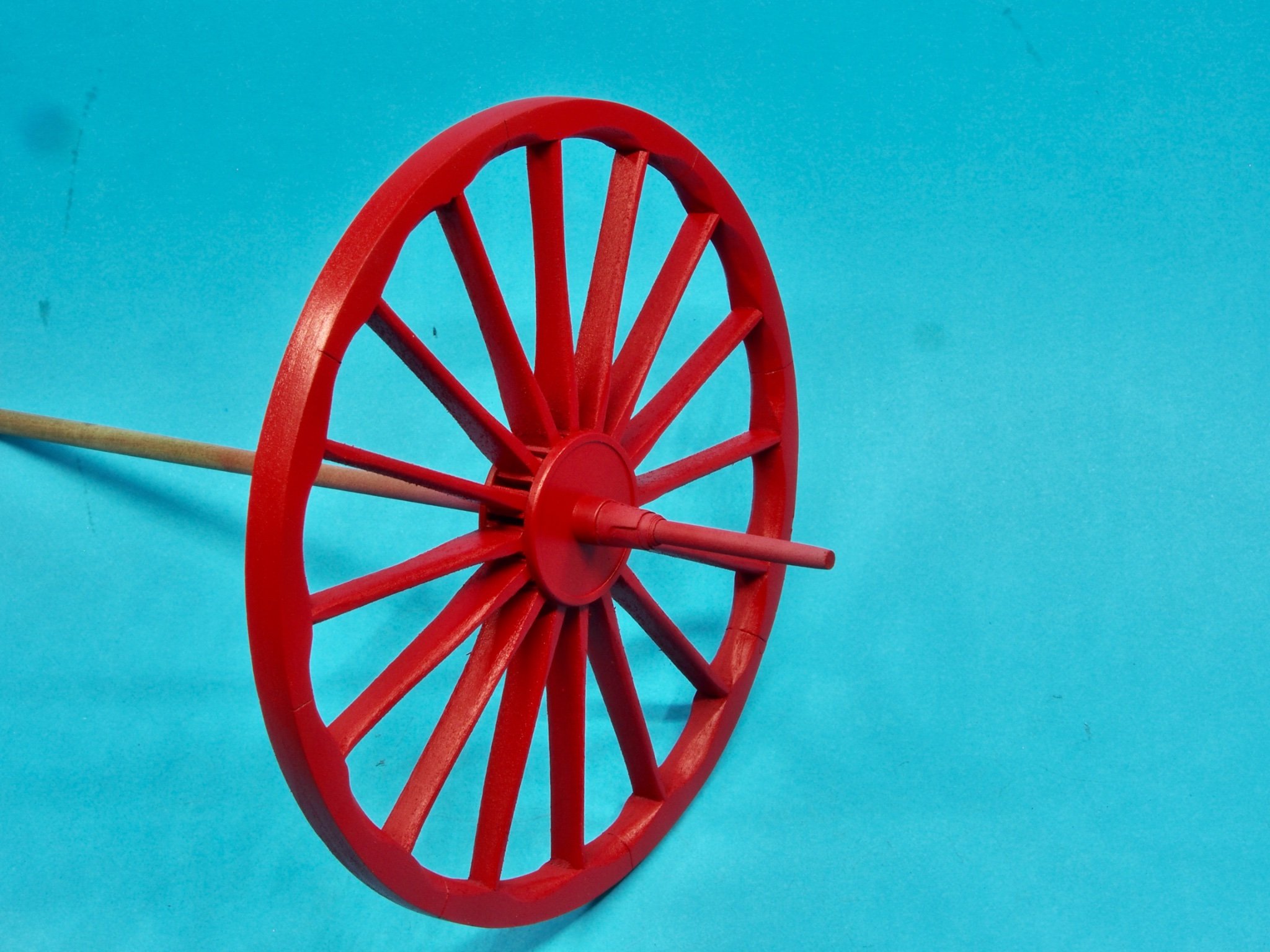
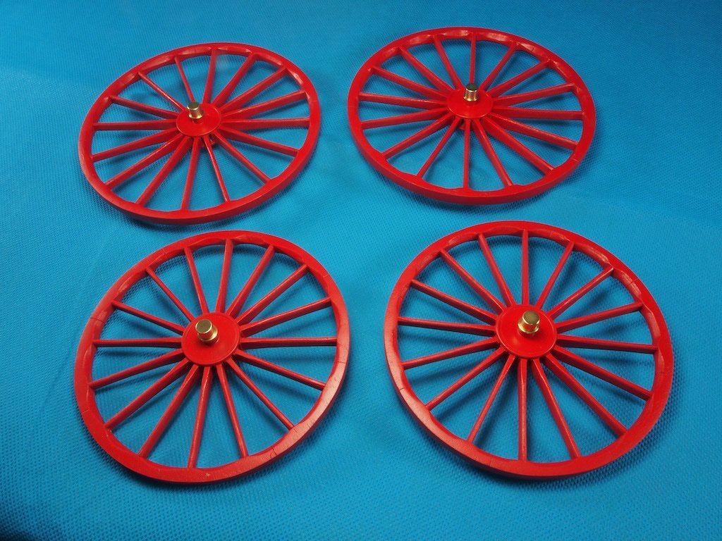
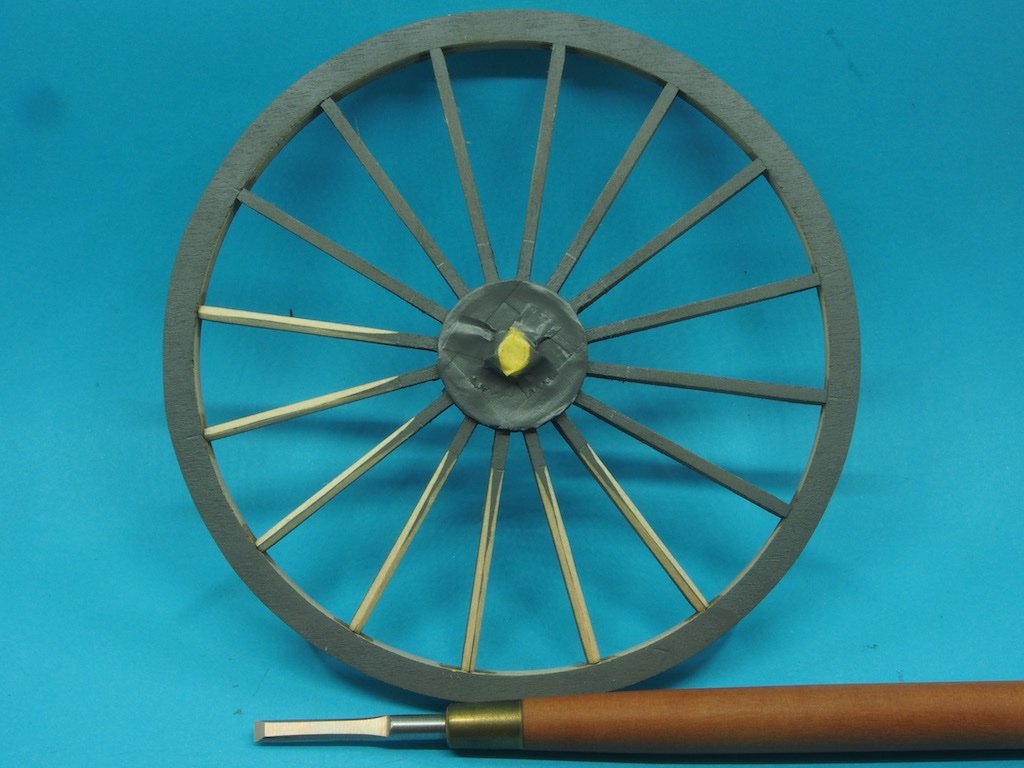
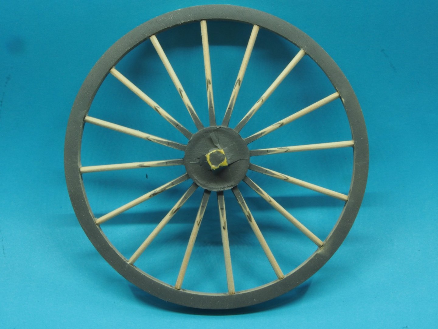
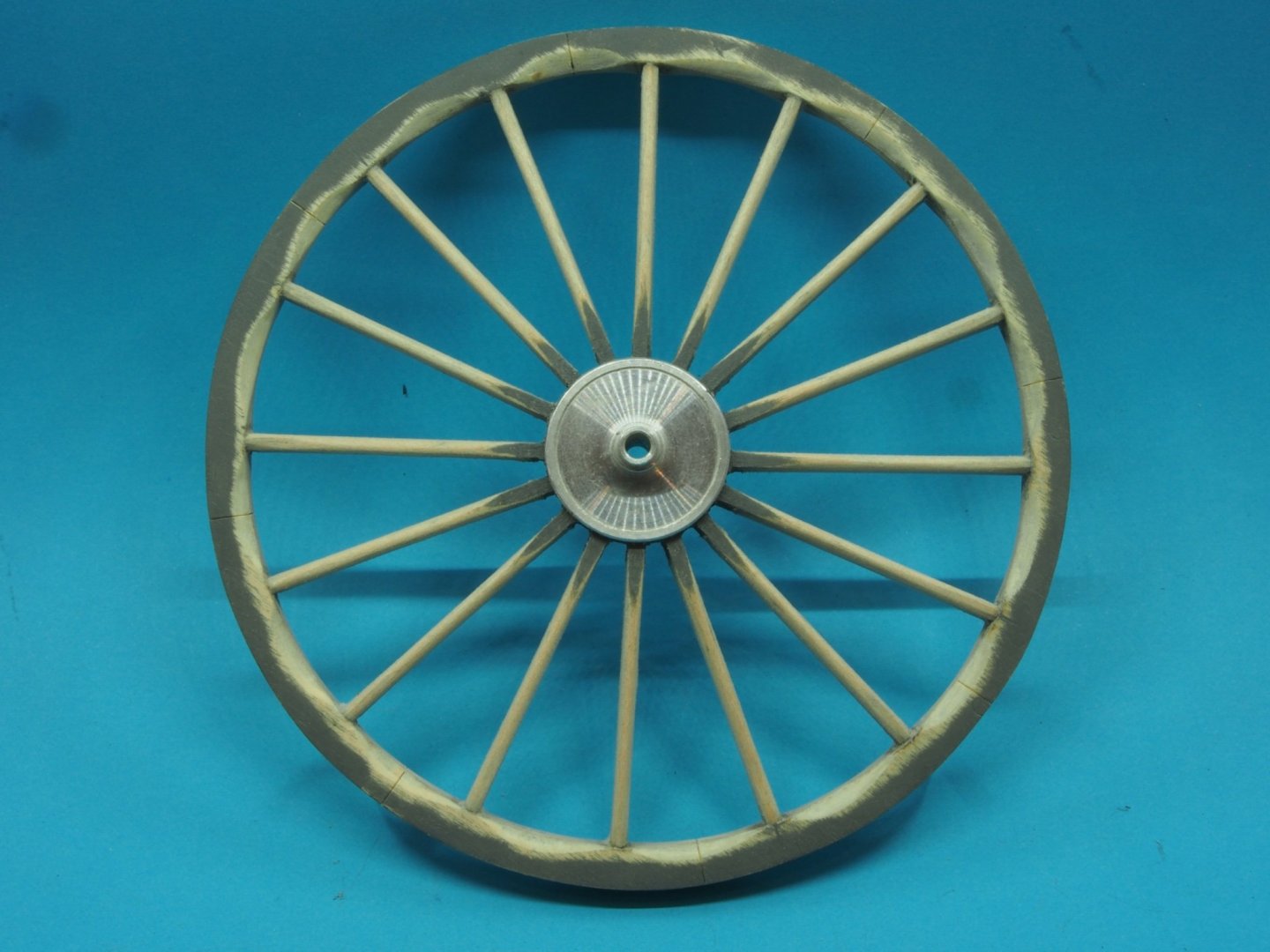
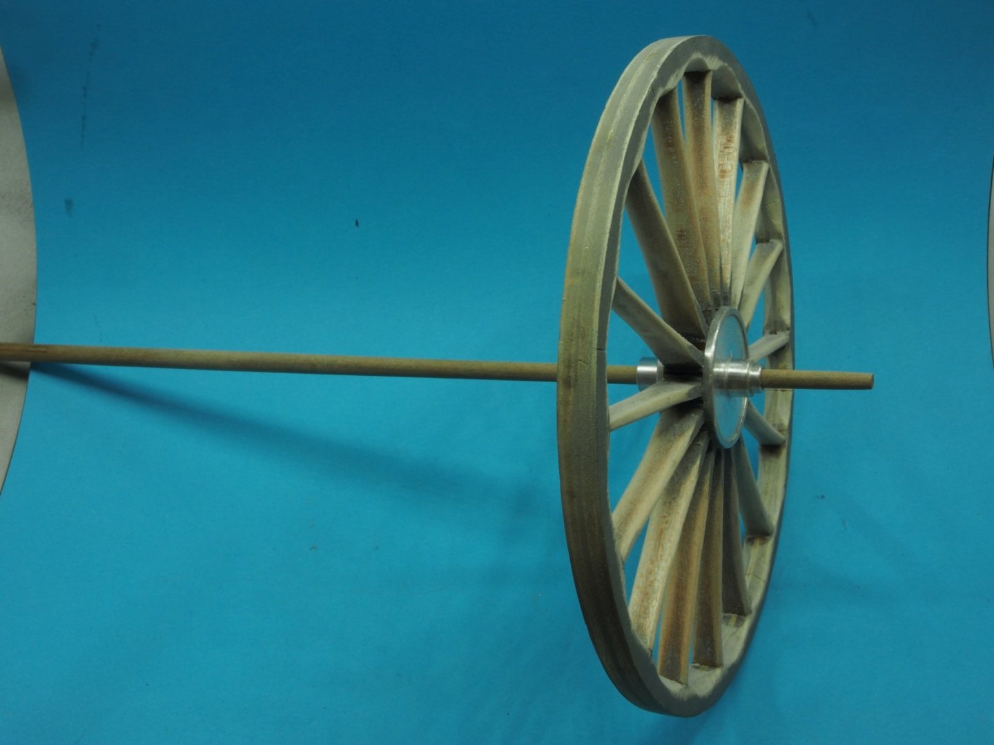
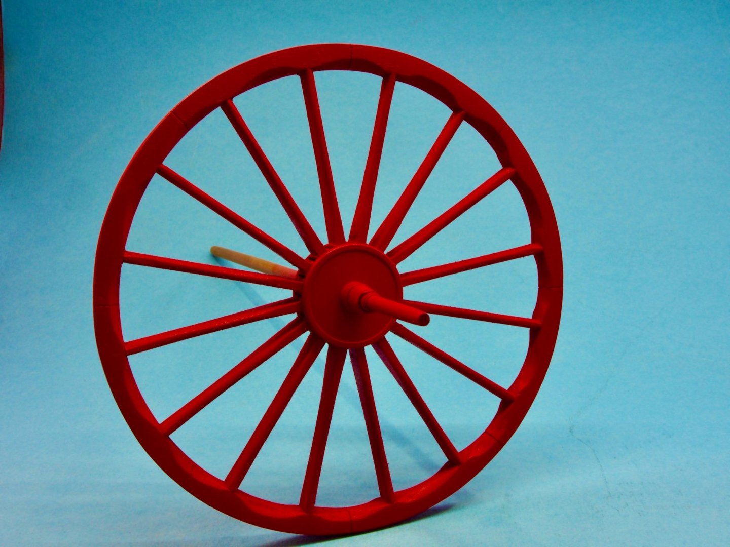
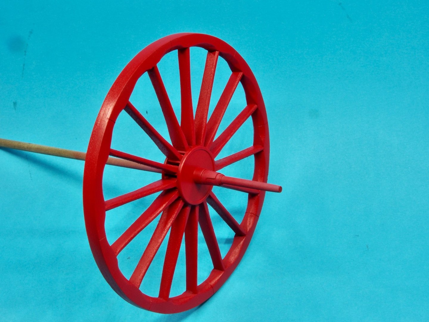
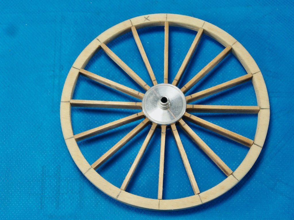
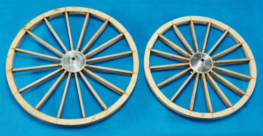
Thanks for the kind comments folks, and for the likes. Wheel Construction continued… Once all four wheels were assembled, they were given a light sand and a coat of Stynylrez grey primer. The next step is to shape the spokes. The aim here is to have the spokes go from a rectangular cross section near the hub, to an oval cross section at the rim. This is achieved by carefully adding a bevel to both edges on both sides of the spokes and then finishing off with sanding to smooth things out. The instructions suggest using a #11 blade in an Exacto knife to do this. I opted to use my Russian miniature carving tools instead. They made the job really easy! Here is the initial bevelling underway. Having primed the wheel beforehand makes it easy to see what is happening as you go. And here are the spokes after bevelling and sanding: The rims are then shaped by carving out a scallop between each spoke. Again the instructions suggest using an Exacto blade for this. This time I opted to use a couple of small dental burrs in my rotary tool for the initial shaping, finishing up by hand with some sanding sticks. As a final touch, a line is scored across the rim between every second pair of spokes to simulate the joint lines of the rim sections. Here’s what the completed wheel looks like prior to painting: I then needed to find a way to hold these while they were painted. Although the centre hole in the hub is exactly 1/8”, installing them on a 1/8” rod would be problematic as the wheel would still be able to turn. Instead, I found some 5/32” dowel in my stash and sanded a taper on the end until I could fit the wheel over and gently push it to a snug fit. Wrapping tape around the dowel after the wheel was in place prevented it from coming adrift during painting. Here’s the set-up: And here’s the painted wheel, still awaiting a clear coat finish. After painting two of the wheels, I ran out of Red paint. I ordered some more a week ago but it'ss still in transit. I'm now at a standstill until the new paint turns up…
- 138 replies
-
- 14
-
-
-
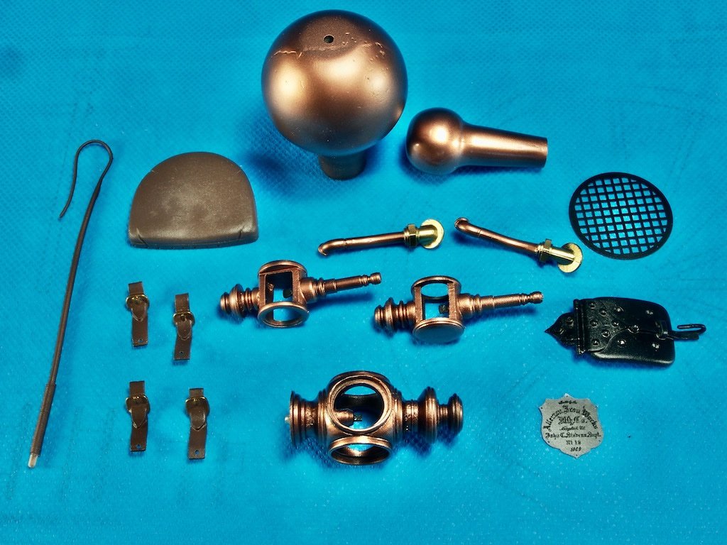
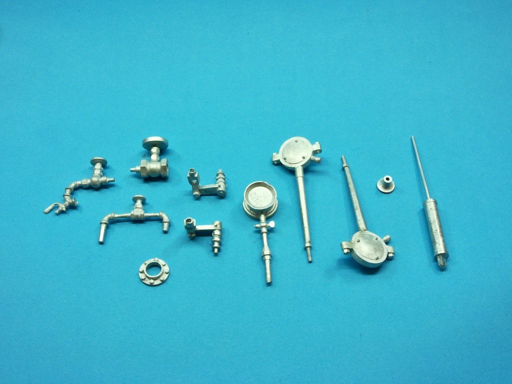
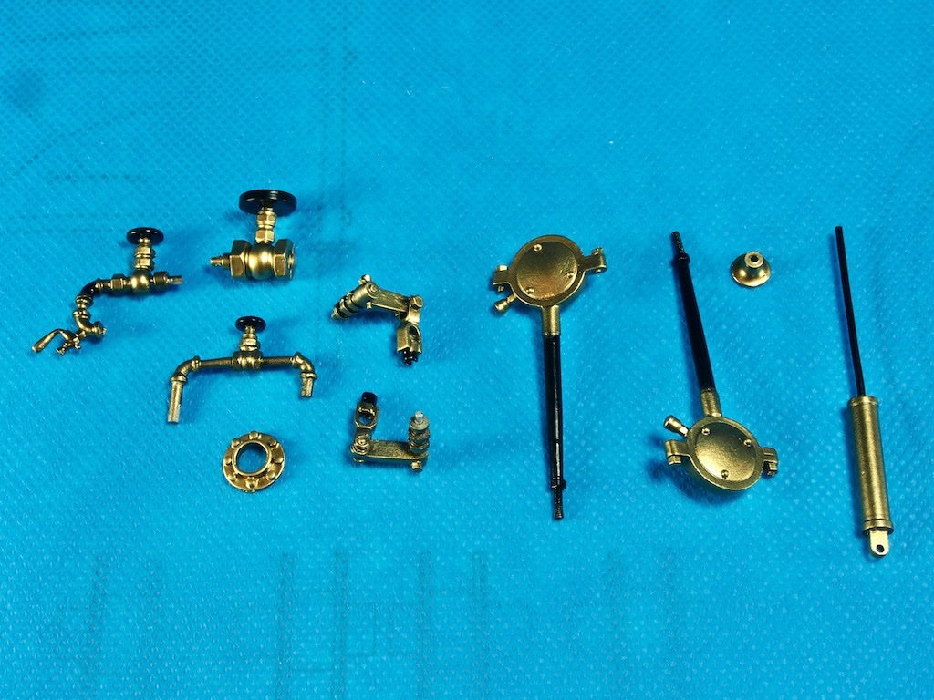
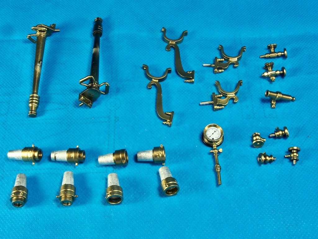
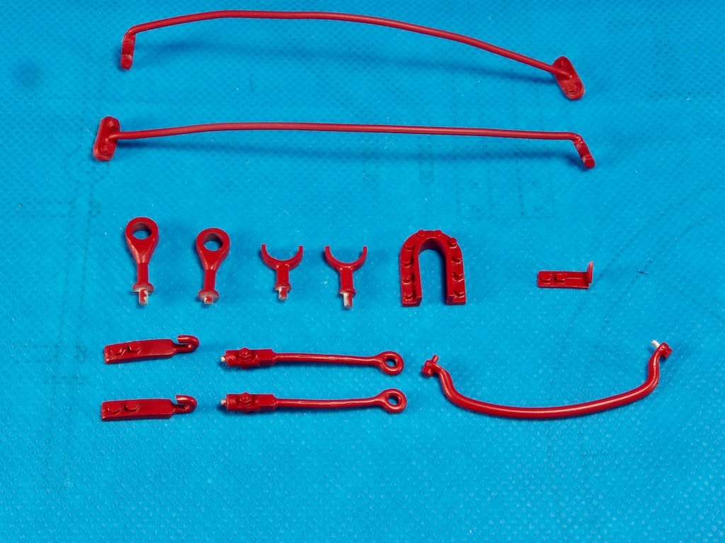
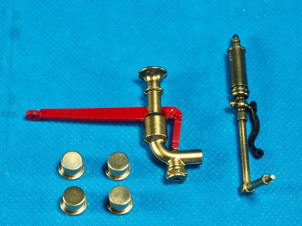
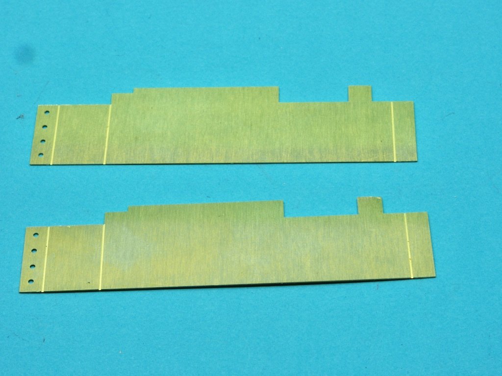
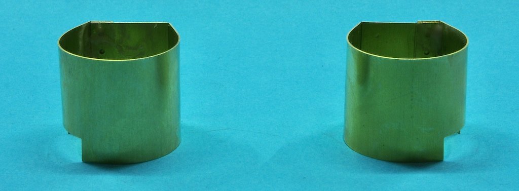
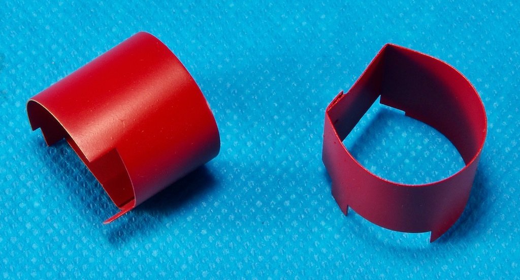
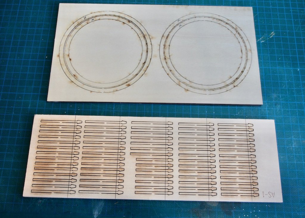
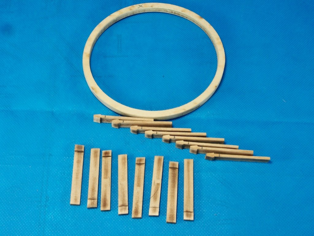
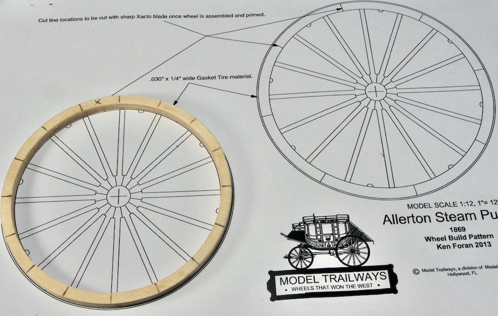
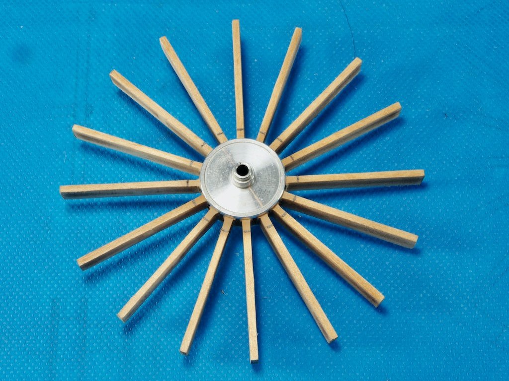
Painting continues… This week has been a bit of a marathon in the paint shop. Here are those Copper, Leather and Black parts all painted up. I added some gold/brass to the buckles on the "leather" straps (bottom left in photo). Hard to see in the photo, but the wicks of all the lamps are also painted black. The engraving on the shield was also painted black. This was achieved by painting the entire shield face, and then wiping over very lightly with thinners to leave only the engraving painted. Next up was some parts that were partly Brass and partly Black: And here they are all painted up: Next up some all-Brass parts (some bits are deliberately unpainted). Note also the gauge face on the boiler gauge: Then some miscellaneous Red parts: And while I had the red paint out, here are the parts for the Brake Assembly: And finally, the Steam Regulator and Steam Whistle. In this photo the four hub caps are at the bottom left. Although there are cast parts for these, they are also provided as machined brass parts. I simply polished these and then gave them a gloss clear coat to stop them from tarnishing. The colour of the painted “polished brass” is a pretty fair match for the actual polished brass. I was about to paint the Axle Limit Chains, but when I looked at the chain provided in the kit, I was disappointed to see that it is nowhere near the correct scale. Here is a picture of the kit-provided chain overlayed on the 1:1 scale drawings: I have found what I think will be a suitable replacement chain and have ordered that. Should be here in a week or so. Coal Buckets… Next task was to make up the Coal Buckets. These are provided as photo-etched brass: And here they are after bending and forming: And after painting: That completes the painting of all the metal components (apart from the Chain). With that mammoth task behind me, it was time to tackle the construction of the Wheels. Wheel construction The wheels are made up from some laser cut ¼” plywood rims, some laser cut basswood spokes, and some machined hubs. The first task is to lightly sand the front and back faces of the plywood and basswood carrier sheets to remove the excess char. Then the back face of the Rims are marked with a reference mark, and the front face of the spokes similarly marked. The reason for this is that because the laser cuts at a very slight angle, by mating the front side of the spokes with the back side of the rims, the angles will mesh tightly. With that done, the parts for one wheel at a time are removed from the carrier sheet and all sides cleaned of excess laser char, being careful not to remove the index marks. The instructions then say to lay the rim over the provided template to mark the position of the centre of the spokes. It was at this point that I realised that the templates had been printed incorrectly and were not properly to scale. Easily fixed – I scanned the template into my computer and reprinted at 94% scale and voila! The spokes are then assembled into the machined hub. This is a clever design and makes building the wheels really easy. At this stage they are just a push fit. Note the reference lines on the spokes near the hub. The Rim is then added to the assembly, taking care to align the reference marks to the spokes, providing nice and even spacing. Once satisfied with the arrangement, thin CA is applied to the spokes, rims and hub and wicked into all of the joints. Here’s one of the front wheels: And now with one of the rear wheels also completed: Two more wheels to assemble to this stage, and then the fun begins with shaping both the spokes and the rims. Stay tuned…
- 138 replies
-
- 17
-
-
Can’t answer your question definitively Andrew, but is it possible that the plans have a misprint - is it possible that where they are calling for .012” it should read .032”?
-
Some great work there Andrew - looking sharp!