


gjdale
-
Posts
4,894 -
Joined
-
Last visited
Content Type
Profiles
Forums
Gallery
Events
Everything posted by gjdale
-
 Thanks Toni - I hadn’t thought of that aspect, but it makes perfect sense now! I’ve been working on milling rebates various lately and am about to tackle the “iron” rings. Will post a proper update soon.
 -
Very nice work so far Rick. Best wishes for your surgery and hoping for a speedy recovery for you.
- 155 replies
-
- 2
-

-
- Medway Longboat
- Syren Ship Model Company
- (and 1 more)
-
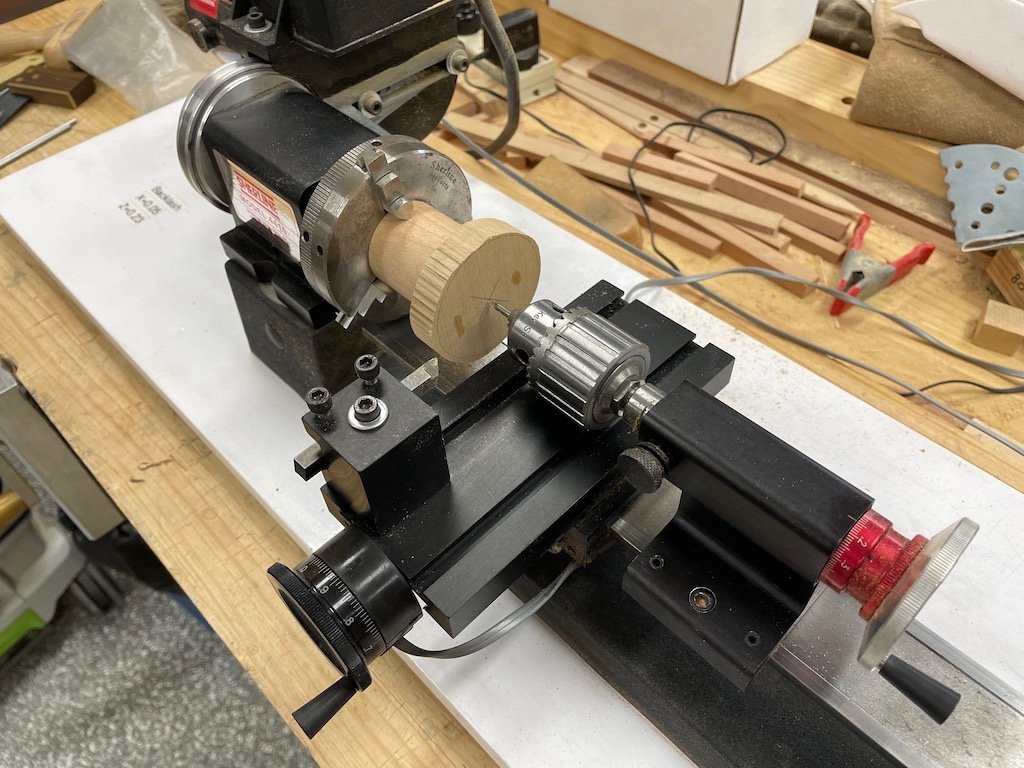
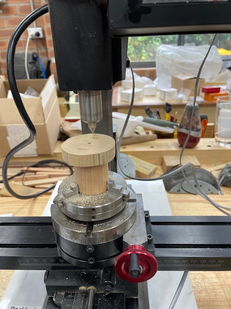
The Drumhead Assembly (P/N 200) From the instructions, the drumhead is made up of six major pieces: two upper and two lower drumhead halves, an iron ring and the cap, along with several miscellaneous bolts and fittings. I decided that I would make each drumhead as a single piece rather than two halves glued together. Upper and Lower Drumheads (P/N 18 & 19) Toni’s instructions indicate that the Drumheads are each made up of two semicircular pieces of wood cut with a jeweller’s or scroll saw and glued together. I’m not sure why Toni took this approach, but assume it was because she didn’t have stock of sufficient width to cut them from one piece. If you’re reading this Toni, you may care to comment. As I had some stock that was wide enough, I decided to make each of these as single pieces. Toni then goes on to describe the milling process by gluing the two halves together temporarily, and then gluing these to a scrap of wood that is used to hold the parts in the vice on the mill. I was concerned about accurately centering the held parts on the mill, particularly with the amount of de-bonding, re-gluing and re-mounting to the mill. I thought long and hard about this and have come up with my own solution to the problem. It may not be the best solution, but we’ll see whether it is successful… To address the centering issue, I thought this would be much easier to achieve if the parts were mounted in a lathe chuck mounted on the rotary table on the mill. That meant that the scrap wood block holding the parts would need to be cyclindrical and held in the 3-jaw chuck instead of square held in the 4-jaw chuck. I don’t own an independent 4-jaw chuck and have more confidence in repeatability from the 3-jaw chuck. The next consideration was how to easily register the center of the work on the mill, and also with each other when re-gluing. As the lower drumhead will have a large-ish square hole milled in it eventually, and the upper drumhead will receive a cap, I decided that if I drilled a 1/8 hole through all the parts, this would solve both of these problems. So far, so good – in theory… Off I went then. I found a nice block of cherry in my scrap pile and cut this down to rough square on the big table saw. I then found the centre and marked a circle of about the size I thought looked good for a holding piece. I cut close to this line on the bandsaw and then mounted it between centres on the lathe and turned it to final diameter – a relatively quick exercise. I faced the ends square and this part was ready to go. I then cut the two blanks for the drumheads from 1/4" Box sheet on the Byrnes saw. I made these as close to square as I could get. I marked the centres and drew a circle on each as a guide to the final diameter. I then spot glued these together. Once these were dry, I carefully spot-glued these to my holding cylinder, and once it was dry I went back to the bandsaw to rough cut the drumhead circle. My plan was to then return the glued up assembly to the lathe and turn down the final diameter of the drumhead. Here is the assembly on the lathe: It was about now that I realised that the diameter of the drumhead was too large for the lathe – doh! While I had it all set up on the lathe, I centre-drilled a 1/8” diameter hole, then followed up with a regular 1/8” drill bit and drilled all the way through all of the pieces, and finally followed up with a 1/8” reamer. The purpose of this was to allow me to use a 1/8” rod to align the pieces when de-bonding/re-gluing, and also as a registration when mounting on the mill. Speaking of the mill, as I could not turn my final diameter on the lathe, I transferred the assembly to the rotary table on the mill and used a 1/8” end mill registered in my locating hole to centre the work on the mill. I was then able to use this set-up to complete turning the final diameter on the drumheads by offsetting the cutter to the required radius (gotta love the digital read out for this job!). Here is the set-up just before commencement of milling. The milling went well, and I was then ready to cut the rebate for the iron ring. Calculating the width of this from the drawings worked out at 9/64”. My choice of end mills does not include a 9/64” bit, so I had a choice of either 1/8” (8/64) or 5/32” (10/64). After some deliberation, I opted for the larger size on the basis that it might make subsequent fabrication of the “iron” ring easier (perhaps slightly less prone to breakage if made from wood). That process went well – very similar to turning the final diameter, only a different offset and cutting to a final depth of 0.5mm (slightly deeper than the 0.4mm (1/64”) called for in the drawings). I forgot to take a picture at this stage as I had just received a weather alert for thunderstorms and large hail stones – I had to cease play and put all the tools away so that I could get the cars in the garage before the hail arrived. The parts are now soaking in an isopropyl alcohol bath prior to separating and regluing to mill the rebate in the other drumhead.
-
Nice start Rick. This is a great and fun little project. Just remember to take your time, particularly with the planking. Chuck has done what he can to make it easier for us, but it still needs careful attention as you build.
- 155 replies
-
- 1
-
-
- Medway Longboat
- Syren Ship Model Company
- (and 1 more)
-
Nice job on the Capstan Step Eric - very clean joints. Re the Capstan spindle, I did exactly what you are contemplating and drilled a hole with a standard sized drill bit (5/8” for me, but I’m in a different scale to you). You are absolutely correct that it won’t be seen, so make life easier for yourself where you can.
-
Well done Eric! Some very neat looking joints. On your last point re matching mortices, it is better to mark both pieces at once. If you hold them together in a vice, with the ends flush, it should be a relatively easy matter to scribe across both pieces. Even if you only make a small knife mark with the tip of the knife in each, you can then complete the layout line with the pieces separated and proceed as you have described. This guarantees alignment without having to rely on your accuracy using a measuring device. My mantra is to never use a ruler/tape measure when I can use a referential measurement like this. Again, this is full-size practice in furniture making.
-
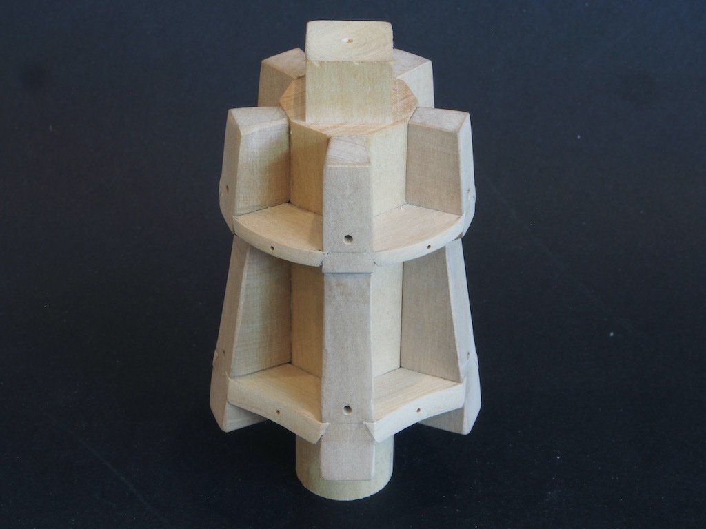
After some minor distractions over the Christmas/New Year week, the build continues. The Chocks (P/N 030 and 031) There are two sizes of chocks, with the lower one being thicker than the upper, and the angles of insertion being slightly different. They are essentially a wedge shape when viewed from above, but their sides are also tapered to match the notches cut into the whelps. To simplify construction, I drew up a plan for each in CAD using the dimensions from Toni’s drawings and then duplicated each of these to provide a strip of five templates for each of the upper and lower chocks. The templates were printed onto sticky label paper and attached to the relevant stock size. The stock was then taken to the Byrnes saw and ripped to a width that would leave plenty of extra length on the chocks for fitting, and then the individual chocks were cross-cut using the angled mitre gauge. The Byrnes disc sander was then used with the table tilted to an appropriate angle (about 30-deg) to trim the sides to a loose fit. The table was then returned to its 90-deg setting and the inner ends slowly sanded away until the chock was a tight fit. Each chock was marked with its location and the barrel also marked accordingly. The chocks were then glued in their respective locations and left overnight. Once dry, the excess material was removed firstly at the Byrnes disc sander and then with files and sandpaper to achieve the final shape. The concave face on the lower chocks was achieved by firstly making a rough shape using the oscillating spindle sander, and then refining with a contoured sanding block. Finally, the whole assembly was remounted in the 3-jaw chuck on the rotary table on the mill and the bolt holes were drilled in the chocks. I opted to drill these at 0.7mm diameter to accept some 40lb monofilament for the bolts. This is somewhat thinner than specified but looks about right to my eye. I got so focused on the process, that I forgot to take any progress pictures. Here is the completed Capstan Body. Next up, the part I’ve been dreading – the Drum Head Assembly….
-
Further to Kurt’s excellent advice, it looks to me from the photos that you used the digital calliper and a pencil to mark both edges of the mortice, which will inevitably lead to a loose fit. Use calliper and pencil to mark the rough position of one edge, then use a knife to mark the actual cut line (notice how much thinner the knife line is compared to a pencil line). Then use the carling itself, held in place against the knife line with a small square and mark the second edge, again with a knife. If you use the knife to get really tight against the carling, or perhaps even just under the edge of it, you will end up with a tight joint. The knife lines will provide you with a good reference line to make your saw cuts with a razor saw prior to chiselling out the waste. As Kurt has said, this is how furniture makers do it.
-
Nice progress on the planking Andy.
-
Thank you very much Mark, Kevin, Bob, Gary and Patrick for your kind words, and to all of the “likes” as well. The model has grown further on the Admiral, who has now requested (nay, ordered) that it take up permanent residency in its “temporary” home in the dining room. Although it has felt at times that the model fought me every step of the way, to have this reaction to the end result instead of just “tolerance” makes it that much more worthwhile. 😊 I’ll be having a case made for it in a week or so when businesses start back up after the Xmas break.
-
Thanks for that explanation Egilman - that makes sense now. 👍😊
-
Hey guys, Can anyone (other than Richard, who has spent enough time on this already!) answer this for me please? When I play the file within Dropbox, it is the edited version that runs for approximately one hour, however if I download the file, it downloads as the unedited 4 hr 40 min version. Any clues as to why this is so and/or how to download the shorter, edited version? (I'm using a Mac, in case that makes a difference). BTW, thanks to those who suggested using VLC - that fixed the sound issue I was having.
-
Hi Richard, Thanks so much for doing this. I just followed your link and it appears that you've put an edited version up in Dropbox that runs for about one hour. However, when I downloaded it from drop box, it seems to download the full 4hr 40min version. Any idea why this is so? (I'm not all that familiar with using Dropbox, so it could well be "operator error"). Also just discovered that with the long version that downloads, there is no sound at all.......
-
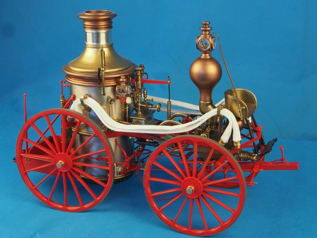
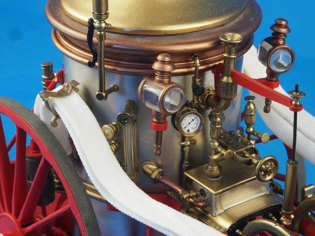
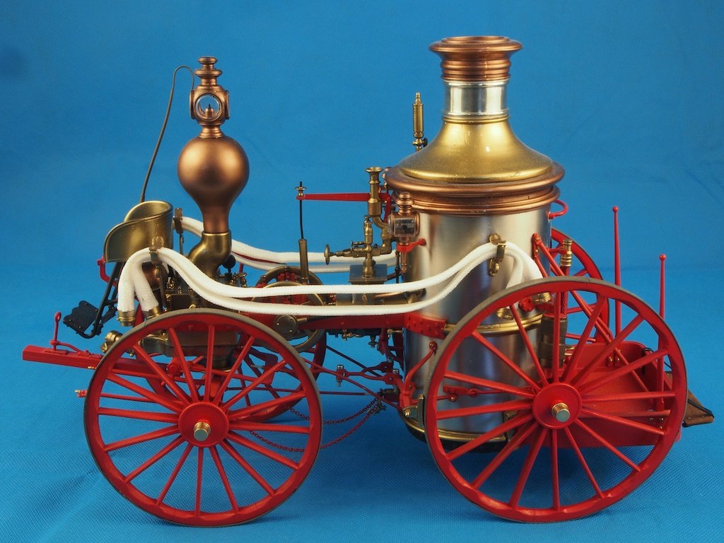
Final Completion After a frustrating couple of months waiting for parts, the model is finally completed. I managed to source locally (relatively) some clear plastic rod of the correct diameter to complete the boiler gauge sight glass. I also took some time to write a constructive email to Model Expo with a detailed list of the errors in parts, and in the instructions, that I had encountered and asked only for replacements for the hoses and three bolts. I figured that since Model Expo claim a free parts replacement service this shouldn’t be too hard, especially since I had gone to the trouble of clearly identifying the issues for them. Turned out not to be quite that simple. It was only after I involved the company owner (Marc Mosko) that I even got a response to my emails – the first email went completely unanswered for a month before I wrote a second time. Then a person in the parts department took it upon themselves to make it more difficult than it needed to be by insisting that I complete their online form for replacement parts, even though I had already provided every single piece of information on that form and more. That same person also told me that I would receive exactly the same parts as originally provided (never mind that the parts were incorrect). I was not prepared to put up with this nonsense so once again drew Marc Mosko into the conversation. Someone must have received the proverbial kick in the pants because I was then contacted by someone else in the parts department who couldn’t have been more helpful. The only further snag was that because of the cost of postage these days, they decided to include my replacement parts in a shipment to their Australian distributor, who would then forward my parts on to me. I can’t fault them for that – in fact it was a sensible approach. Anyway, the parts finally arrived on 29 Dec (more than two months since my first email) so Model Expo did make good on their promise and I’m grateful for that, even if their customer service is somewhat lacking. Once I had the hose material in hand, it was a simple matter to cut them to approximate length, dip the ends in CA glue to stop them fraying and while the glue was still wet, insert the end of a paintbrush to open the ends and stop them sticking together. Once the CA had dried, the hose ends were trimmed to final length and the hose connectors inserted and glued in place. The hoses were then painted with a liberal amount of watered down PVA glue (50/50 glue/water mix) and left overnight to dry. This made the hoses relatively stiff but still malleable and able to be formed to some sort of shape prior to installing on the model. So here at last are some final shots of the completed model. The Stbd side: A close-up of the Boiler Water Level Sight Gauge: And the Port side: Despite its many frustrations, this has been an enjoyable build and I’m well pleased with the final product. More importantly, the Admiral likes it, and it is now on display in a temporary home in the dining room. Now I can get back to finishing my Capstan project.
- 138 replies
-
- 19
-
-

-
A good mantra to remember is: “Every machine in your workshop is actively trying to murder you!”
-
Glad to hear that you escaped without serious injury. Table saws always scare the c**p out of me, which is why I invested in a Sawstop Table Saw. Doesn’t replace the need for vigilance with safety, but does prevent those serious injuries.
-
That must have been frustrating for you Bug, but you’ve made a very nice recovery.👍
- 419 replies
-
- 2
-
-
- Victory Models
- Pegasus
- (and 2 more)
-
At the risk of “teaching grandma to suck eggs”, to get accurate joints, mark your cutting lines with a knife rather than a pencil and use referential measurement whenever you can (eg mark the first cut line for a mortice from the given measurement from the end of the piece, then mark the second cut line by placing your tenon piece against the first cut line and using it to define the width for the second cut line). Hope that makes sense.
-
Hey Eric, A couple of things I found in using my spreadsheet: In addition to having a table of the stock dimensions, I have found it useful to create an extra box to enter specific or one-off measurements and have the computer spit back out the appropriate scale dimensions in fractional inches, thousandths, and metric. I could then write these onto Toni's drawings as needed. Like you, I am "bi-lingual" when it comes to imperial/metric measurements. Although I use metric for the lathe and mill because that is how they are geared/calibrated, I have found it much easier to stick with imperial units for everything else as the conversion to scale size seems to be generally a little "cleaner" to use (eg an inch ruler might have 32nds marked on it, but a metric one doesn't have x.3mm etc). The digital caliper with both fractional and decimal inches (as well as mm) is your friend! For accurate mortises, a knife line and a very sharp chisel are the key to success (as I'm sure you know from your other woodworking).
-
Well done on your victory over the PE Mark, she’s looking great!
- 505 replies
-
- 2
-
-
- vanguard models
- Sphinx
- (and 1 more)
-
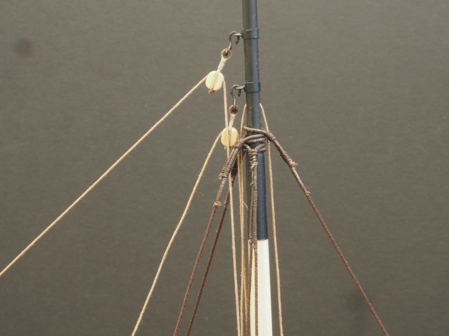
Floyd, If you take a look at post #87 in my log you will see a photo of the top of the mast and it shows quite clearly where the line has been served, and then seized to form the loop. I’ve copied that photo for you below, but please feel free to delete if it is cluttering up your log.
-
Dave, A little research on your subject ship should tell you the actual sizes of the various blocks and ropes used. The Anatomy of a Ship series is often a good start. There are various other sources that can provide guidance on typical rigging sizes used for your size of ship for its particular time period. Once you have that information, just create a spreadsheet to convert the actual size to your chosen scale in the measurement units of your choice.

