


gjdale
-
Posts
4,894 -
Joined
-
Last visited
Content Type
Profiles
Forums
Gallery
Events
Everything posted by gjdale
-
 Floyd, To stat and finish serving, I use a sewing needle to pass the serving material through the line being served. A touch of diluted white glue on completion just for added security does the trick for me. Not sure I understand the second part of your question.
 -
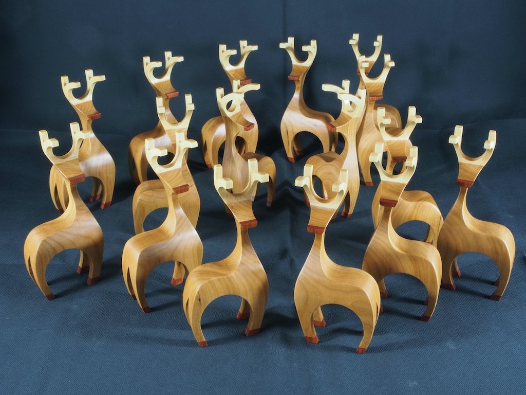
Thanks Glen, Apart from three requisitioned by the Admiral, all of the other reindeer were given away to family and friends, where they all received warm welcomes into their new homes.
-
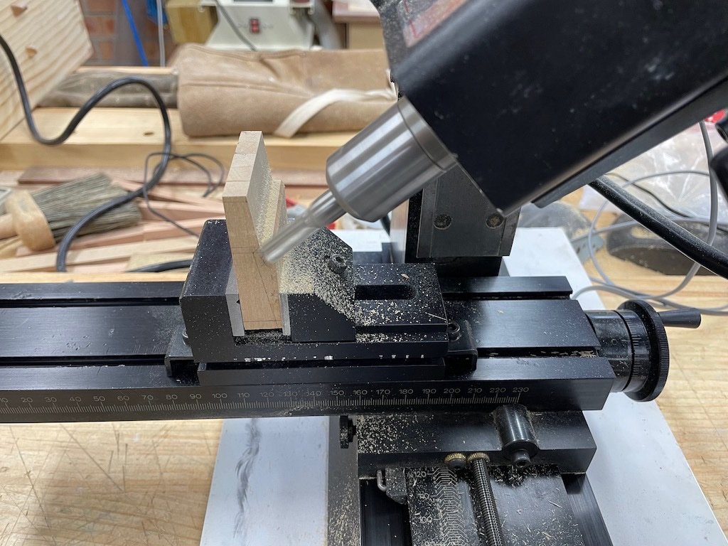
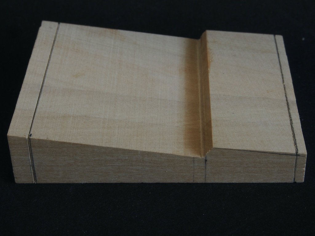
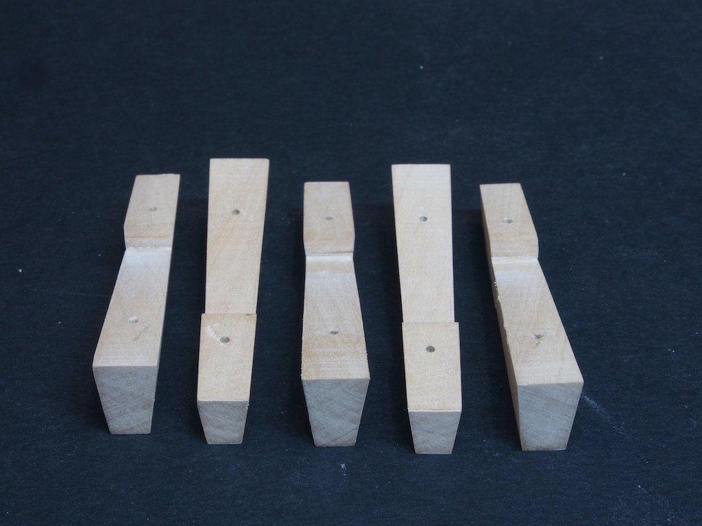
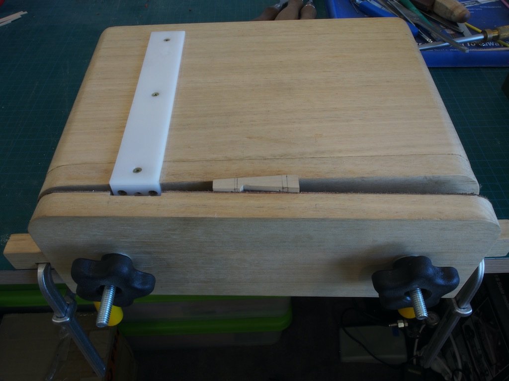
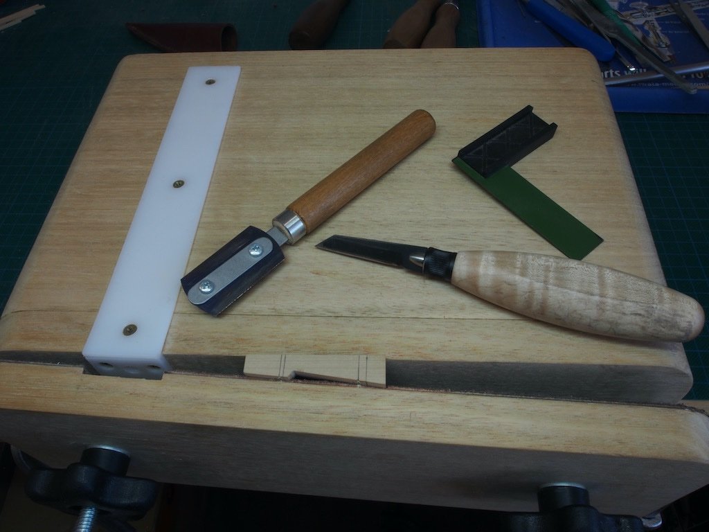
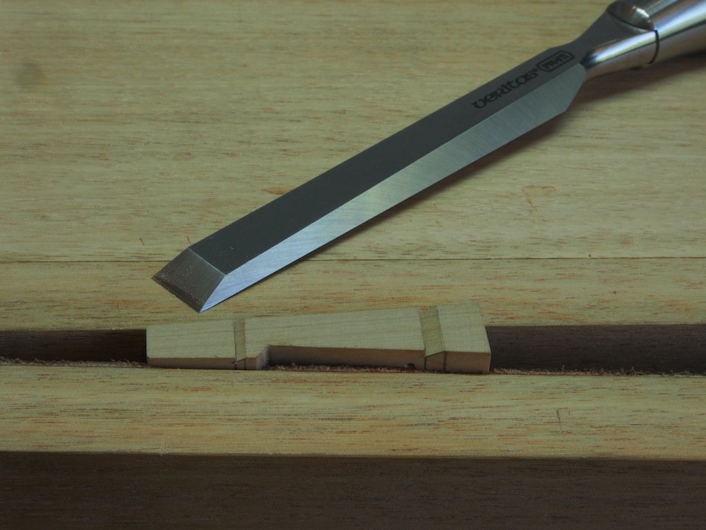
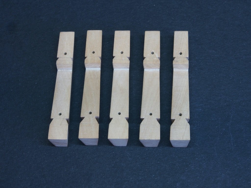
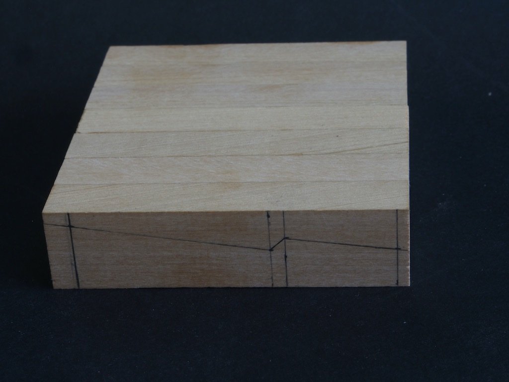
Thanks for the kind comments Ben and Rusty, and for all of the likes. Life seems to have gotten in the way lately, so progress has been slow. The Whelps (P/N 029) Five Whelps are required and the particular challenge in making these is that they are tapered both top to bottom and rear to front. The first step was to cut some blanks and then glue them up into a sandwich with the basic profile outline on one face. Toni’s advice in the instructions was to make a couple of spares, so initially I glued up a set of seven blanks. Unfortunately, when it came to milling the sandwich, I found that it was too wide for the mill travel, so I had to unglue them and re-glue with just five in the sandwich. The basic profile was then cut on the mill by angling the milling head as shown by Toni in the instructions. Here is my set-up halfway through the milling process: And here is the end result. Note that the blanks were left slightly long to allow for any chip-out during milling. The blank was then taken to the Byrnes saw and trimmed to length prior to soaking in an IPA bath to separate the individual pieces. Once separated, holes were drilled for the bolts and the individual pieces carefully marked out for the tapers. The top to bottom taper was tackled first, and is relatively simple to achieve using the Byrnes disc sander to freehand sand to the marked lines. The rear to front taper was a little trickier. After carefully marking out, the angle was measured using a protractor and the tilting table of the Byrnes sander set to this angle. With a little care, the correct taper was achieved. Here are the pieces after all tapers had been cut/sanded. The next challenge was to cut the notches for the Chocks. Like many things in woodworking (or metal working for that matter), the hardest part of the process is working out how to hold the work securely for the operation at hand. Having carefully marked out each piece for the notches, I found that my home-made Moxxon style vise was able to cope with the tapers quite well to hold the work. I then used a miniature square and a marking knife to score the vertical cut line. This then provided a handy registration for the razor saw to make the vertical cut. A freshly sharpened full sized chisel was then used to pare the angled cuts. Having worked out how to hold the pieces, the actual cutting of the notches went quite quickly. Here are the completed Whelps. The Chocks will be next but will probably have to wait a day or two until after the fat man in the red suit has been.
-
Congratulations on completing a fine build Andrew. You can be justifiably proud of your results.
- 161 replies
-
- 1
-

-
- Model Shipways
- Emma C Berry
- (and 1 more)
-
Nice trick with the wedge Andrew - thanks for sharing.
-
Big THANK YOU from me too Richard. A really valuable session and learned heaps. Sorry I had to duck out just before you finished - I had another commitment to attend. Best wishes to you and your family for the festive season.
-
Great job Tom, well done!
-
You must be a glutton for punishment Ben, having both Pegasus and Winnie on the go at the same time! Either that or you have waaaay too much time on your hands! 😀
-
FLoyd, I’m not sure what you are referring to here. If you’re talking about seizing of blocks and you are seeing gaps they are unintentional. If you are talking about securing the tail end of a shroud or stay, then there are two seizings with a space between them. I can’t remember how many “wraps” I used for each - just until it looked about right.
- 109 replies
-
- 1
-
-
- medway longboat
- Syren Ship Model Company
- (and 1 more)
-
Floyd, Thanks for the kind comment on my seizings. There are many ways to do the seizing. The way I do them may not necessarily be correct, but they seem to look okay. I generally just use a simple series of overhand knots tied on alternate sides of the seizing. I start furthest from the block and work back towards the block, so that the seizing closes up the gap. I then put a dab of diluted PVA on the entire seizing and trim the ends once dry.
- 109 replies
-
- 1
-
-
- medway longboat
- Syren Ship Model Company
- (and 1 more)
-
Just stunning Gary. As others have noted, it is only when one sees the last photo with your glasses next to it, that the scale can be truly appreciated. Bravo Sir!
- 189 replies
-
- 15
-
-

-
Ah - that's good then - a whole 1/16" to spare. What could possibly go wrong? 😁 I'm still a couple of weeks away from starting my Amati Hannah - gotta get this Capstan Project finished first (thanks for looking in).
-
Glen, I might be pointing out the obvious here, but....... Your bottle neck opening is 11/16". Your scale model breadth is 3/4" (ie 12/16") Do we have a problem?
-
I’d be happy to help with emptying the whiskey bottle Glen! This sounds like a very interesting build and I love your idea for display. I’m taking a front row seat for this one. 😊
-
Great work on the paint job Mark. Even the “wall side” looks good to me.
- 505 replies
-
- 6
-
-
- vanguard models
- Sphinx
- (and 1 more)
-
Floyd, I bought my LoS online (can’t remember the supplier now, but a quick Google search should provide some options). The one bit of advice I’d offer here is to buy the LoS in gel form. Then you can put a very small blob on a paint palette, put a drop of water next to it, and then dip a paint brush where the two meet. I find this technique provides a good strength solution, without getting too scientific about ratios. I think it was Ed Tosti who first suggested that approach to me. Anyway, it works for me.
-
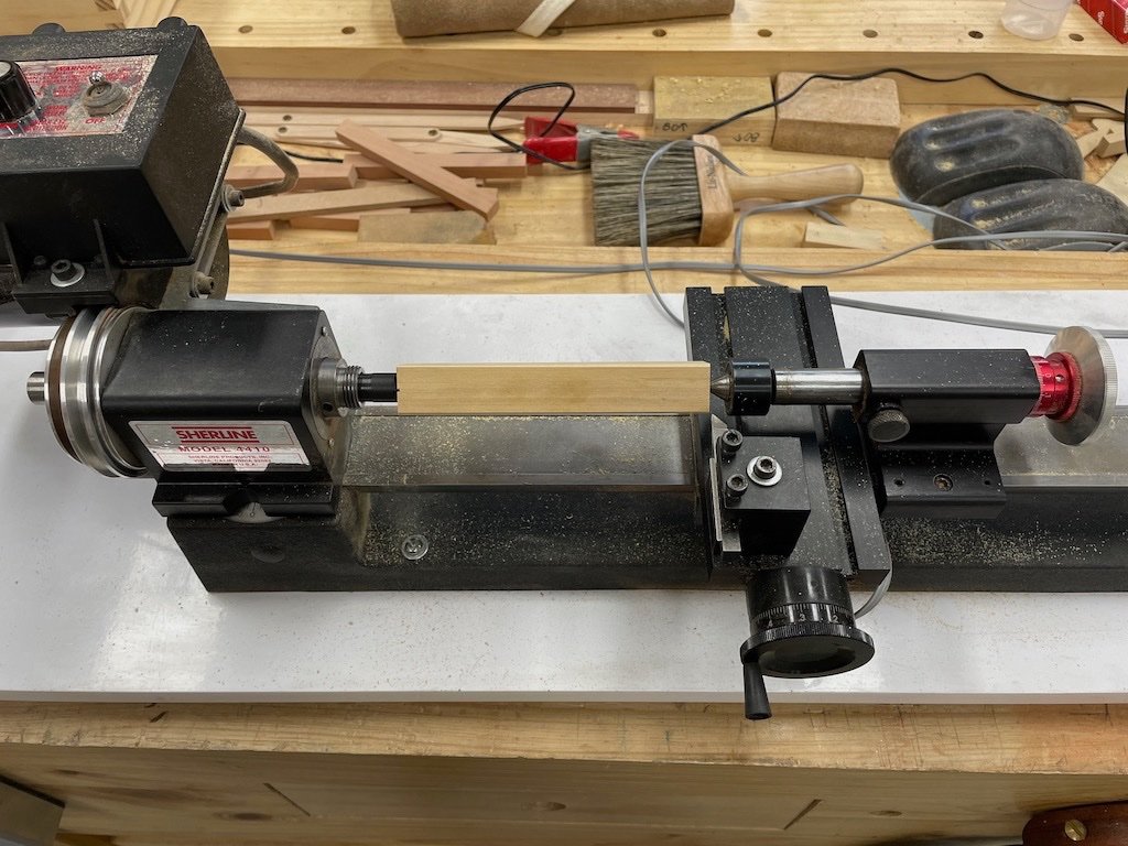
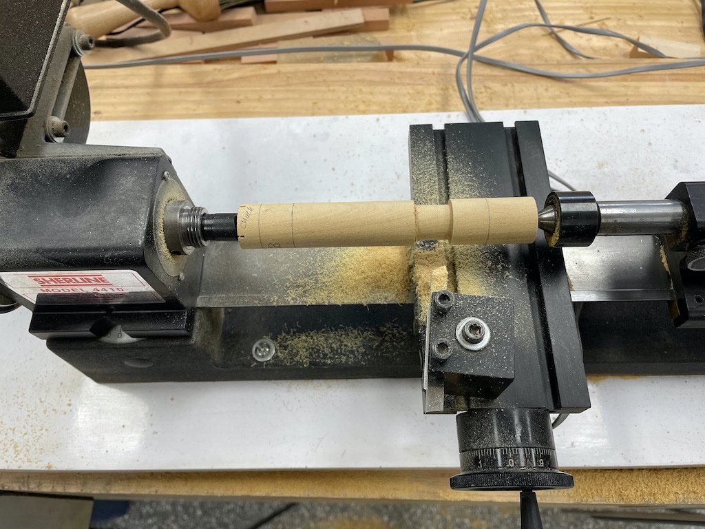
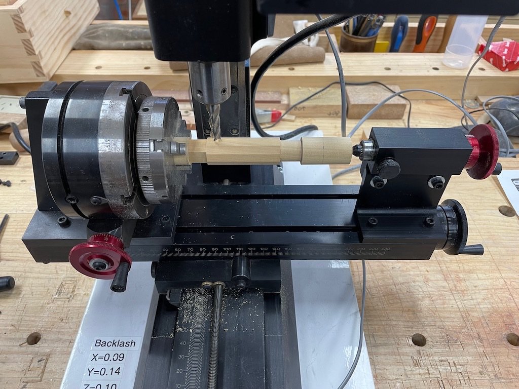
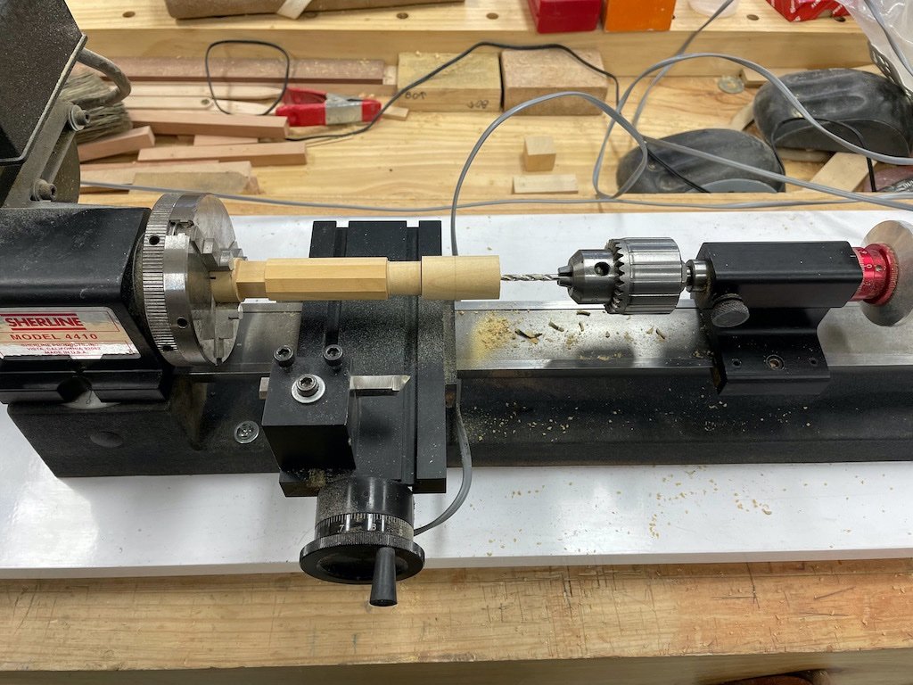
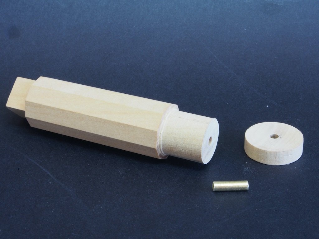
After a brief side project making some bandsawn Reindeer Christmas decorations, it was time to proceed with the Capstan Body. The Capstan Body is assembly P/N 300 and is comprised of the Barrel (P/N 301), the Whelps (P/N 029), the Chocks (P/N 030 and 031), and the retaining pin assembly (P/N 303). Barrel (P/N 301) The barrel, while made from a single piece of timber, has a varying cross section. At the top it is square, the mid-portion is ten-sided, and the lower part is circular, with a stepped section for the gasket. The retaining pin assembly is also cut from the same piece of stock. All of these cross-sections are achieved using a combination of the lathe and the mill. It all starts with a square blank. The length of the blank needs to be long enough for a little extra length for work holding, but short enough that it will fit in the mill mounting arrangement (seen later). Rather than mounting the (not-quite) square blank in a four-jaw chuck and leaving the extra length square-ish in section, I opted to mount it between centres and turn the entire length, which would subsequently allow me to mount it in a three-jaw chuck. Here is the start of the process. Once the entire length was turned down to the maximum diameter of the barrel, the narrower sections for the gasket and the part that will go through the Capstan Step were turned down. The part was then removed from the lathe and inserted in a three-jaw chuck, which was mounted on the mill rotary table, which was attached to a right-angle mount. The “tail” end was supported using an adjustable tailstock holder. Here is the overall set-up, which facilitated milling of the ten-sided section and the square top section. In this photo all of the milling has been completed. All of that sounds easy, and it is if you pay attention to correct set-up of your mill – which I failed to do on the first attempt. It had been quite a while since I had used the mill and I simply forgot some of the basics. After a failed first attempt, I started over and this time spent the necessary time to align the rotary table in both the Y and Z axes, and to align the tail-stock holder properly with the chuck. A little bit of fiddling to be sure, but really the only way to ensure that your final product will be what you intended, within the tolerances you intended. The part was left in the chuck and the chuck removed from the rotary table and returned to the lathe for the next operation. After using a 1/8” centre drill to start the hole, a regular 1/8” drill bit was used to drill through the excess material, through what would become the retaining pin assembly, and into the base of the capstan body. This departs slightly from Toni’s drawing and is a little bit of a “cheat”, but was the easiest way to ensure that the holes for the retaining pin aligned perfectly. The main body was then separated from the retaining pin assembly and cut roughly to length at the top (square) end. The main body was then reversed in the chuck and the square end cut down to final length by a series of facing cuts on the lathe. Similarly, the retaining piece was cut to rough length with a hand saw and then re-inserted in the chuck and trimmed to final length with another series of facing cuts. After test-fitting the assembly, I found that the retaining piece needed to be significantly shorter than shown in the drawings in order that it not extend below the deck beams. This was a simple fix – the piece was marked to a new final length directly from the deck beams and re-inserted in the lathe for another series of facing cuts. A piece of 1/8” diameter brass rod was cut to length for the retaining pin (P/N 028) and epoxied into the retaining piece (P/N 027). Here is a picture of all three pieces prior to gluing the retaining pin in place. The Whelps are next….
- 43 replies
-
- 12
-
-

-
Coppering looks great Bug. As for protecting it, I think you only need to seal it to prevent it from oxidising, so a couple of coats of WOP as you suggest should do the trick.
- 419 replies
-
- 2
-
-
- Victory Models
- Pegasus
- (and 2 more)
-
The blue looks good Andy. I think your choice of colour scheme will make a nice point of difference to other Confederacy builds out there.
-
Very sorry to hear of the loss of your furry friend Andrew. At least you will still have the fond memories of her and Izzy will no doubt be a comfort. Don’t rush to get back to your model - it will be there when you are ready and you have put far too much hard work into her not to give her the full attention she deserves moving forward. We’ll keep a light on here for you in the meantime.
-
Best wishes for your upcoming Op, Mark. I agree with the others re the yellow ochre paint, but don’t rush it - just check under your signature again….the wood is patient…….
- 505 replies
-
- 8
-
-
- vanguard models
- Sphinx
- (and 1 more)
-
Hey guys, I think we might be drifting a bit here. Unless I've misunderstood, I think HOF was asking for advice on glues with a longer open time, not a quicker setting solution. Apologies if I've got the wrong end of the stick here.
-
Just as an afterthought HOF, you might consider using Hide glue. I know that Titebond make a ready to use version (no need for heating glue pots). It has a long open time and is easy to use without a lot of mess (no more than white glue anyway). On this side of the ditch its available through Carbatec and other woodworking supply stores.
-
You may need to look further than a local hardware store HOF - specialist woodworking stores, or boat building supplies stores (or either on line) will likely be more successful for your search. Look for something that advertises “long open time” or words to that effect.
