


Ian_Grant
-
Posts
2,156 -
Joined
-
Last visited
Content Type
Profiles
Forums
Gallery
Events
Posts posted by Ian_Grant
-
-
Bill, if you sanded a hexagon into the middle of the dowel yard the hexagon "tips" would be flush with the adjacent round part ie the flat faces would be recessed compared to the adjacent round part of the dowel. This would make the yard weaker in the centre which is nonsense.
Adding six strips to make the hexagon is the solution; this way the hexagon area is stronger. That said, I don't like Occre's picture; it looks like the yard has been broken by a cannonball and they've fished "splints" around it. Make it all the same colour. And I'd be tempted to sand the flats thinner than they are, until the centres of the flats are only a little proud of the rounded part.
-
-
3 hours ago, Kevin-the-lubber said:
When you get your machine feel free to message for tips etc. I'm no expert but I have learned a few things through trial and error!
ps. Just remembered an important thing worth mentioning before you buy. These budget printers are great for printing common materials like PLA and PETG. You will struggle to print ABS and exotic materials which require higher hot end or bed temps, or high ambient temps and so on. So while you’ll see lots of advertorial around different filaments, it’s as well to be aware that most of these will be outside the scope of your machine, regardless what the blurb implies.
Yes I was aware of this. I have no plans to print ABS as it is toxic and we have a parrot in the house. Birds are very sensitive to odours and airborne chemicals. The Envirolaser people assure me I can print "PLAwood" etc with a stainless nozzle as opposed to a hardened one.
I decided to go all out and get an A1 tomorrow. Looking forward to trying some prints.
-
-
-
STOP THE PRESSES!!!!!
I just noticed on the Bambu web site that their Black Friday sale starts on Monday morning!!
The sale price on the A1 is $379, as opposed to $450.
The Mingda will be go for $230, as opposed to $320 which I just paid.
What to do?
I'll be talking to the 3D store people tomorrow.
- Canute, Glen McGuire and mtaylor
-
 3
3
-
-
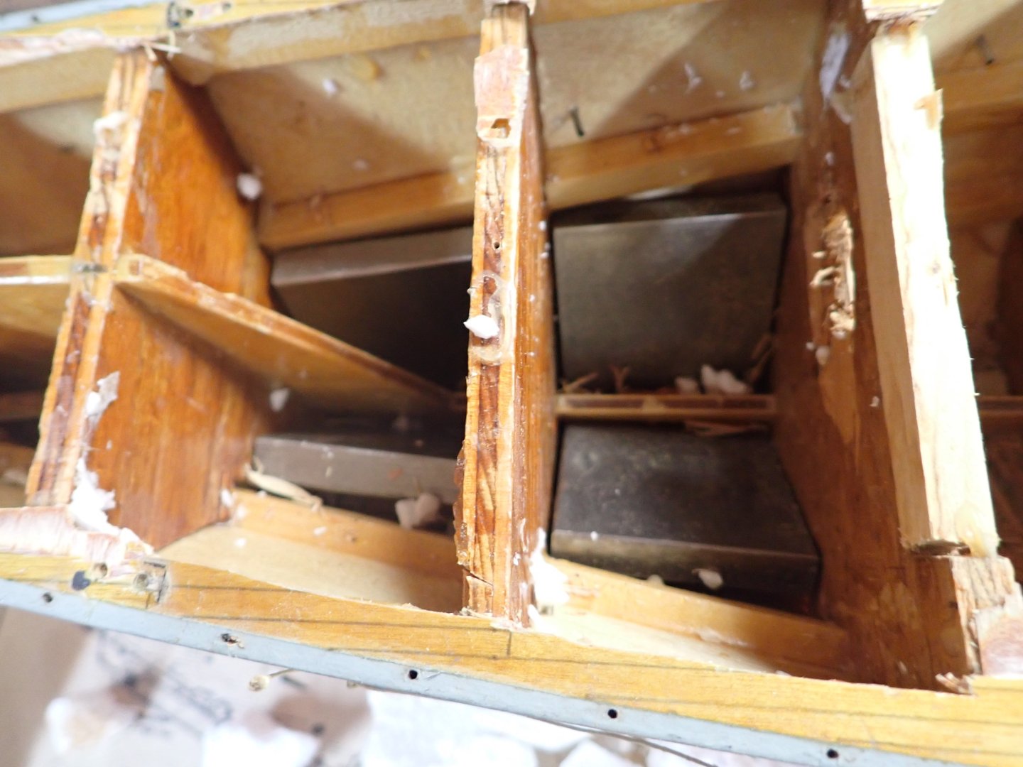
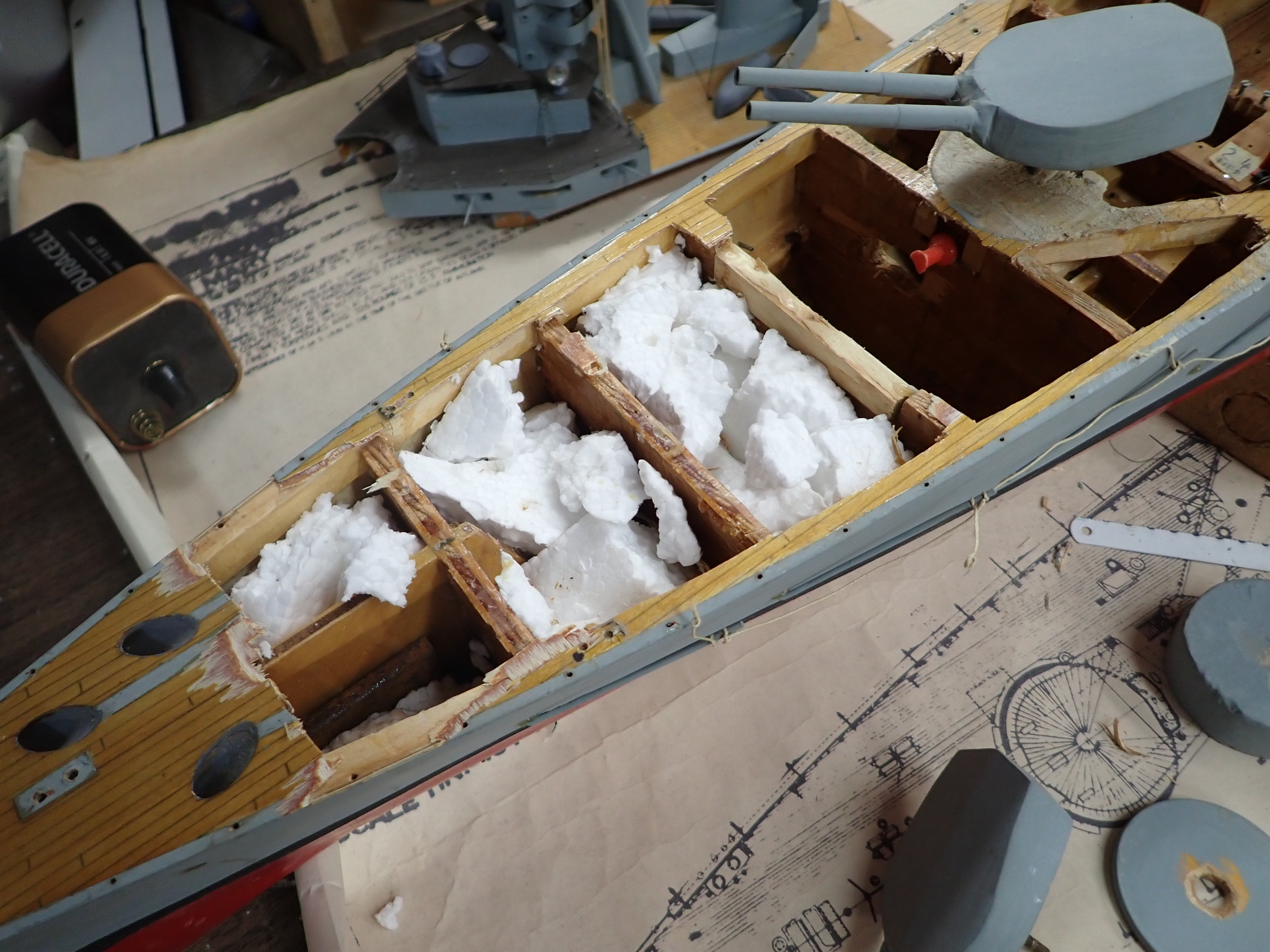
Tore off the foredeck (while saving all the brass bollards, cleats, etc) to reveal things that I had forgotten......
I packed the forward inaccessible cavities with bits of styrofoam, I suppose to provide buoyancy in case of a leak. Or, it might have been to prevent the metal ballast from clunking around. Yes, I did put metal in there before adding the deck; I guess I did a flotation test in 1977 and realized that a lot was needed. Those of you who followed my recent RC Roman Galley build may remember that early on I weighed "Lion" sans motors and other equipment to provide a guess as to what the galley hull might end up weighing. Well, now I know why the bare Lion seemed so heavy, or, why the galley turned out so light and threw off my displacement estimates.
Deck removed: (Why did I leave that red pin in there in 1977??).

Styrofoam removed.....oops, there's ballast in there.
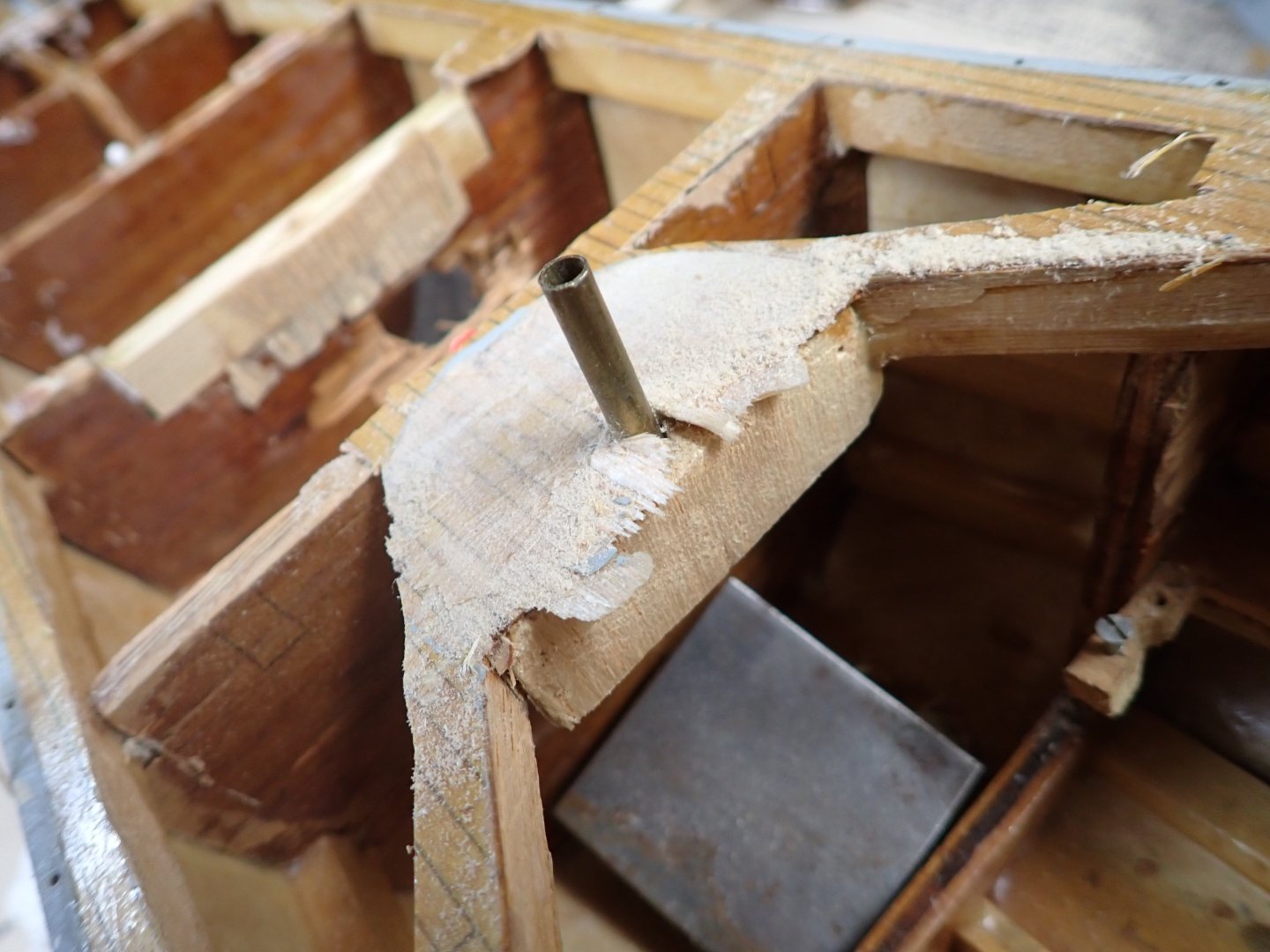
Brass sleeve for "B" turret pivot shaft, after barbette removed. (More metal!).
I pondered how to get 180 deg pivoting at the turrets. Simplest thing I can think of is to mount a toothed timing gear on a servo arm and connect via a toothed belt to another toothed timing gear on the turret pivot shaft. Making the gear on the servo triple the size of the other gives 180 degrees at the turret from a 60 degree servo. I found very nice aluminum timing gears and belts on a robotics web site. Couldn't get ratio=3 exactly, just 2.8 with not-too-large timing gears. Close enough.
So the plan is to have a setup like this for each of "Q" and "X" turrets, ie two individual servos y-connected to a receiver channel to move in unison.
Fingertech provides a simpletool for calculating the required centre-to-centre distance of a given pair of gears with a given belt. See here:
https://www.fingertechrobotics.com/how-to_pulley_belt.php
In the case of the belt joining the "A" and ""B turrets shafts, using two 18T gears and a 70-tooth belt yields centre-centre distance of 78mm which is exactly right for the inter-turret spacing at the scale of this model.
There is a complication for "A" and "B" turrets; they need to turn, in unison, in the opposite direction as the others; eg "X" and "Q" pivot clockwise (seen from above) to train to port, "A" and "B" pivot anti-clockwise to train to port. Plan is to drive "B" shaft from a servo via either two meshing gears, or via belt from a servo which rotates in the opposite direction given the same signal as the other two. I read rumours that this might exist; someone said Futaba servos move opposite to the norm but I will have to check this out. If I find such a servo, it will connect via the belt to a second timing gear on "B" shaft, again with a triple-size timing gear on the servo. If I can't find such a servo, I will connect it to "B" shaft via two laser-cut wooden gears. "A" of course will move in whichever direction "B" moves.
I found an on-line tool which generates an .svg file to laser cut two gears, after you fill in a table of numbers of teeth etc. See here:
https://evolventdesign.com/pages/spur-gear-generator
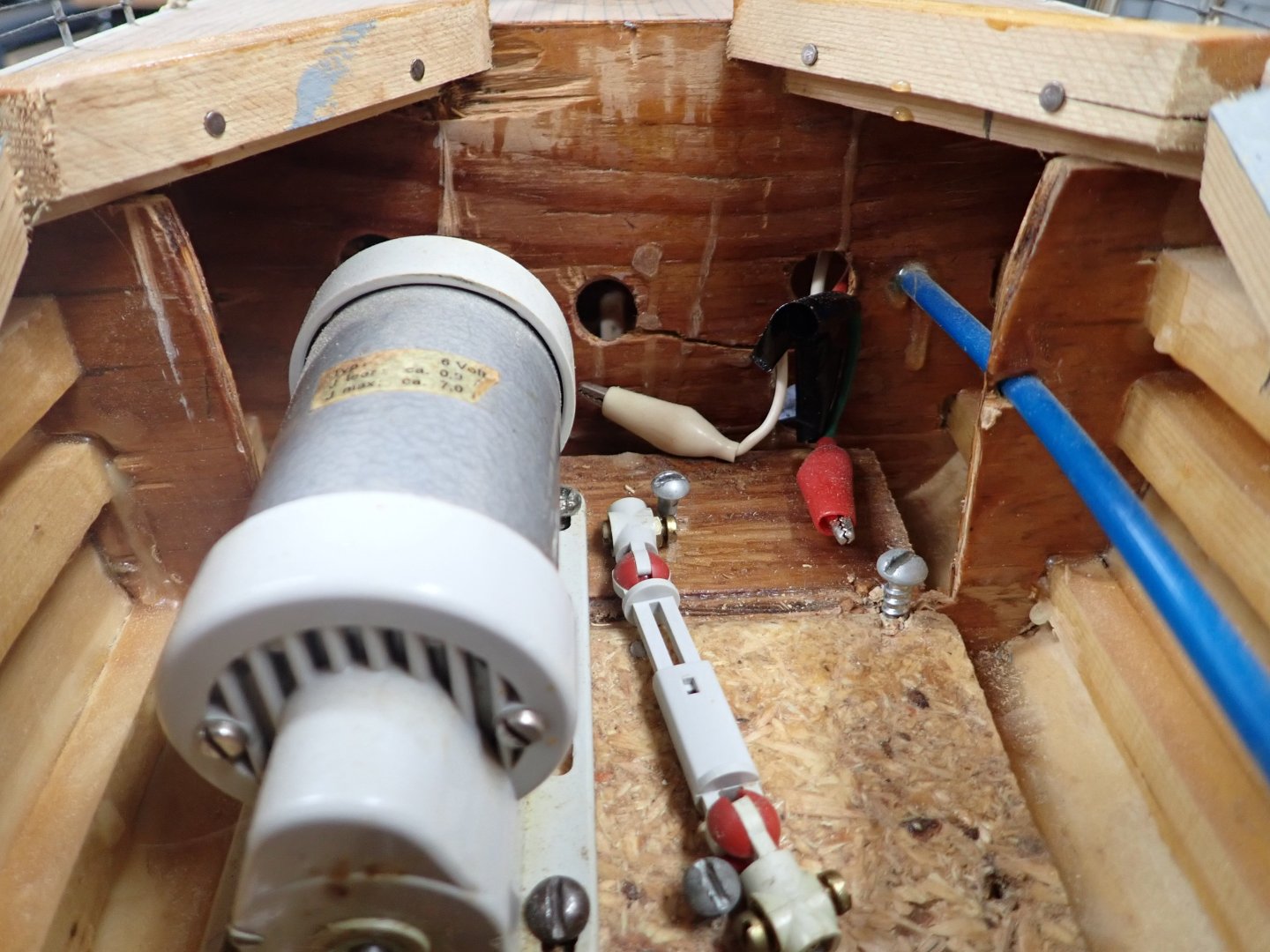
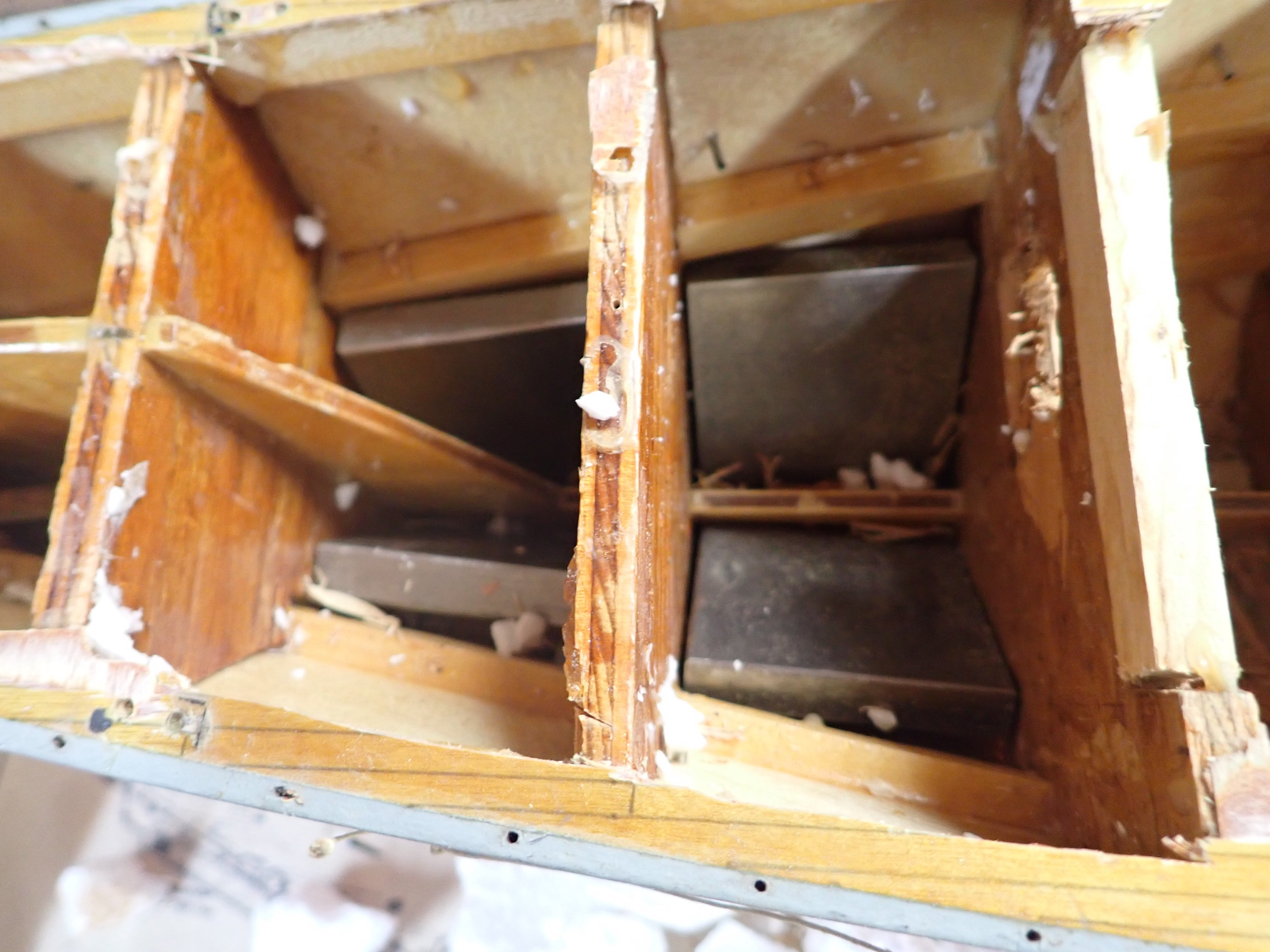
As in anything I build, this hull is very solid; keel plus four stringers a side, 1/4" plywood bulkheads, many solid. I need to carve out the centre of the engine room forward bulkhead; you can see where I hacked holes to get alligator-clipped wires to the motors. Being older and wiser I'll now use bullet connectors meaning the solid ply would be in the way. That blue tube is the RC-aircraft-style cable guide for the rudder linkage. Loose U-joint is for absent motor.
Bow shows a badly-patched square. This was due to my brother's idiot friend George who dropped the unfinished hull while looking at it. Ah, memories!
On another topic, I got tired of having to sit in front of the library's 3D printers waiting for them to finish. Plus, you only get a maximum 3 hour window for a print so there's no time to make anything significant. I decided I want my own 3D printer. Impatient, I bought a Mingda Magician X2 this week, a very nice printer with features making it easy for beginners to use. However, I'm having second thoughts. I was torn between it and a Bambu A1 Mini. Until I get rid of some clutter I can't set it up, and we're away for most of November, so I am going to return it (unopened) and wait to see if the full-size Bambu A1 comes down about $100 on Black Friday at the end of November. This would bring it down to the price of the Mingda and I'm convinced it's an even better printer. If not, I will probably go with the A1 Mini and save $100.
- mtaylor, Glen McGuire, schooner and 1 other
-
4
-
Hard to tell from the nice photos, but are the stacks always centred on the keel line?
I have no knowledge on this topic either, by the way.
- mtaylor, Canute, Glen McGuire and 1 other
-
4
-
On 10/15/2024 at 6:05 PM, Glen McGuire said:
When I first started research on this project, I googled "how to make a whirlpool with epoxy resin" and that video showed up at the top of the list. I perused the entire Minibricks website and was left in awe. They take epoxy resin art to a level that I've never seen before nor thought was possible. That particular video is what I'd like mine to look like (in my dreams, anyway), but doing it inside a bottle makes it a whole 'nother thing!
Glen, I had an inspiration to make it much easier to implement in a bottle. The trick lies in your choice of bottle; something like this:
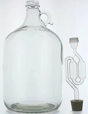 It's a one-gallon wine fermentation bottle. Plenty of room, and a bigger mouth.
- mtaylor, Paul Le Wol, Old Collingwood and 5 others
-
3
-
 5
5
-
Glad to have you watching over me, Keith.
- KeithAug, Canute and Glen McGuire
-
3
-
1 hour ago, tmj said:
Don't make a vase like whirlpool as seen in the video. Just make an inner plug and fill it with bird-shot, or sand so it will hold its shape while being surrounded by wet epoxy resin. When all is said and done, dump out the BB's or sand, pull the mold out and "Viola!" I've seen enough of your work and talent to know for fact that you could indeed pull this off! ☺️
That's how to do it!!!
- FriedClams, BANYAN, Canute and 5 others
-
8
-
16 minutes ago, Keith Black said:
I thought about the approach myself. The problem is the funnel, it would have to fold where it could be inserted into the bottle, then unfold once in position, held in place by magic, gel poured in and the freed from the gel and removed. Too many steps to success in a very tight space plus I couldn't find nary a folding funnel.
What about one of those straws with a corrugated section bent to 90 deg in the bottle, and a funnel attached at the outboard end?
Glen, I would like to propose an engineer's approach. Since you can't make the epoxy spin after you pour, you need to spin the bottle instead. Some sort of cradle to hold it horizontal, with a DC gear motor to do the spinning with the spin axis passing through where you want the centre of the whirlpool, speed controlled by adjusting the motor voltage. There, simple!
 You're welcome. 😉
-
35 minutes ago, Glen McGuire said:
" I spent the weekend doing yard work. "
HaHaHa!
- Paul Le Wol, Keith Black, FriedClams and 1 other
-
2
-
2
-
-
5 hours ago, Canute said:
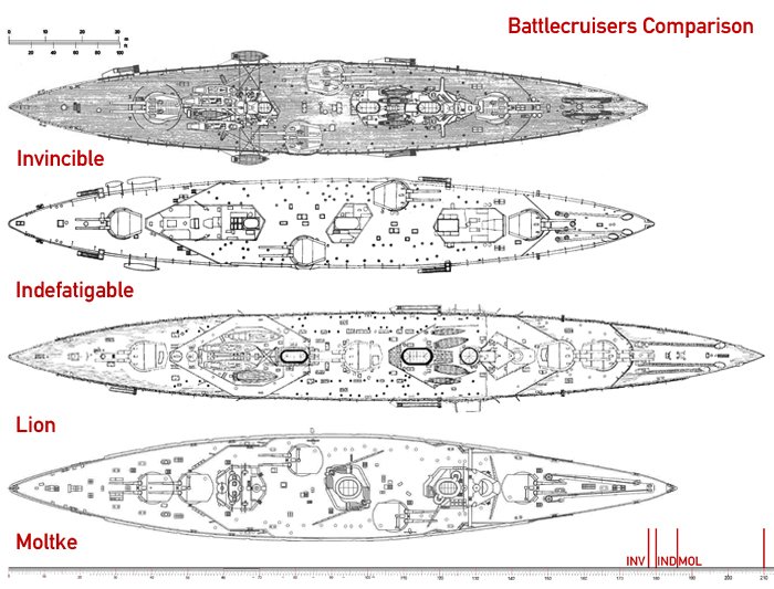
I'll follow along, too. RN battlecruisers are faves of mine.😄
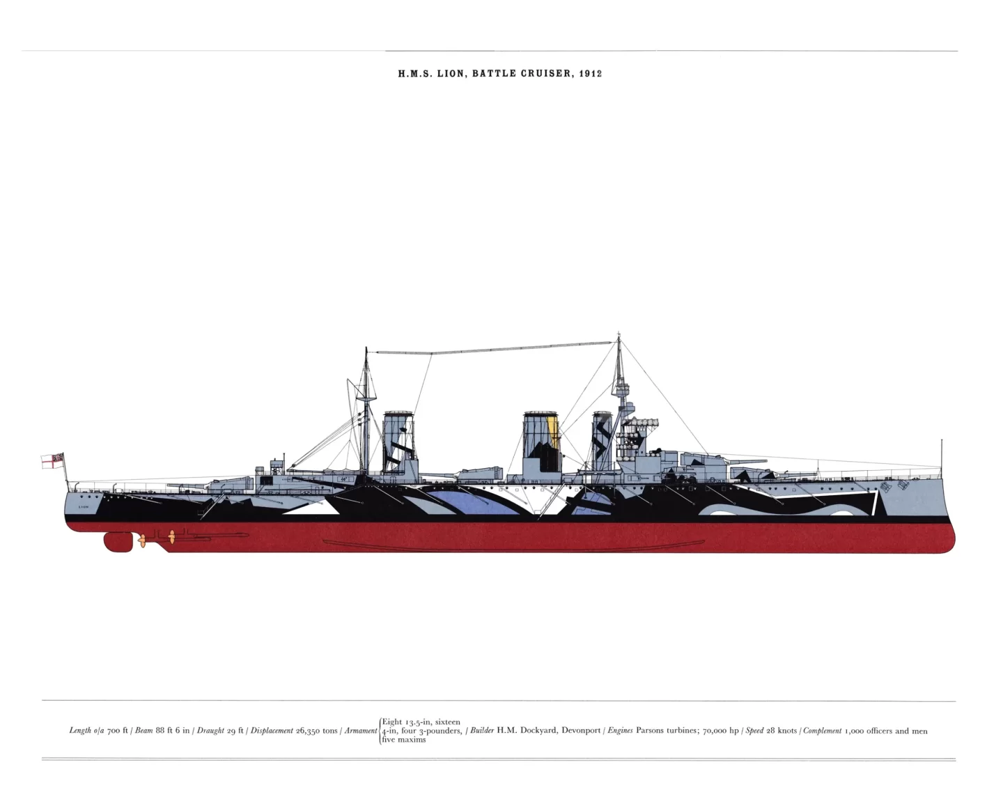
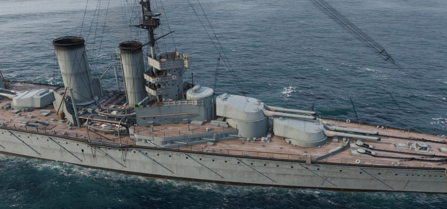
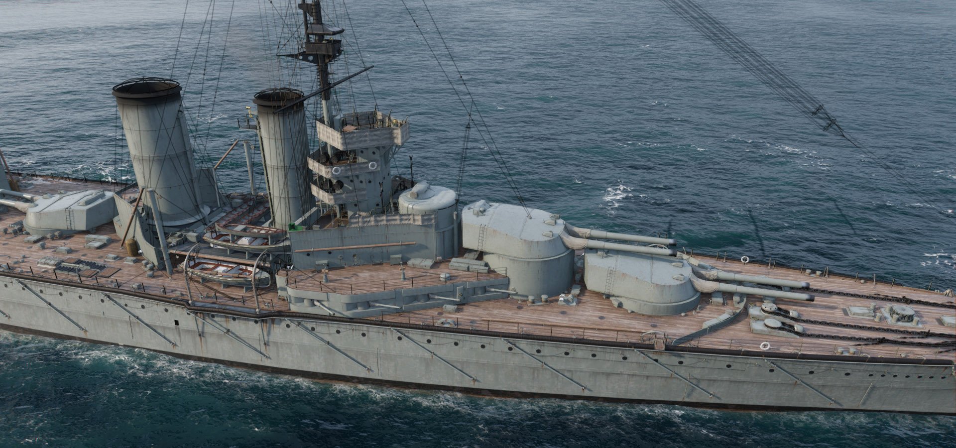
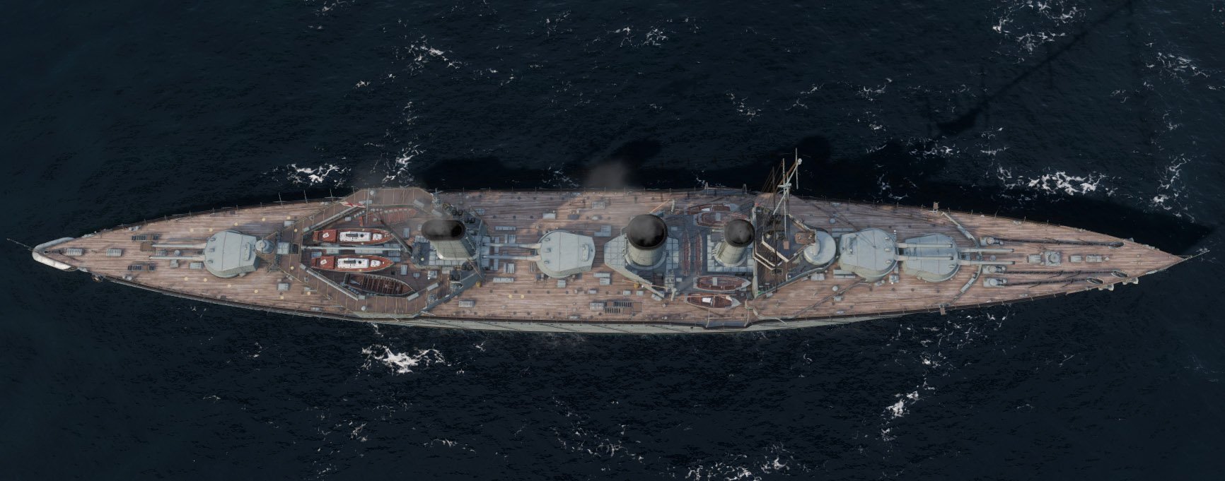
Yes, the Lion class appealed to me even as a teen because of the unusual (to my eye) turret amidships. If I had to start from scratch now, I'd probably make a model of the Neptune class with its two midship beam turrets.
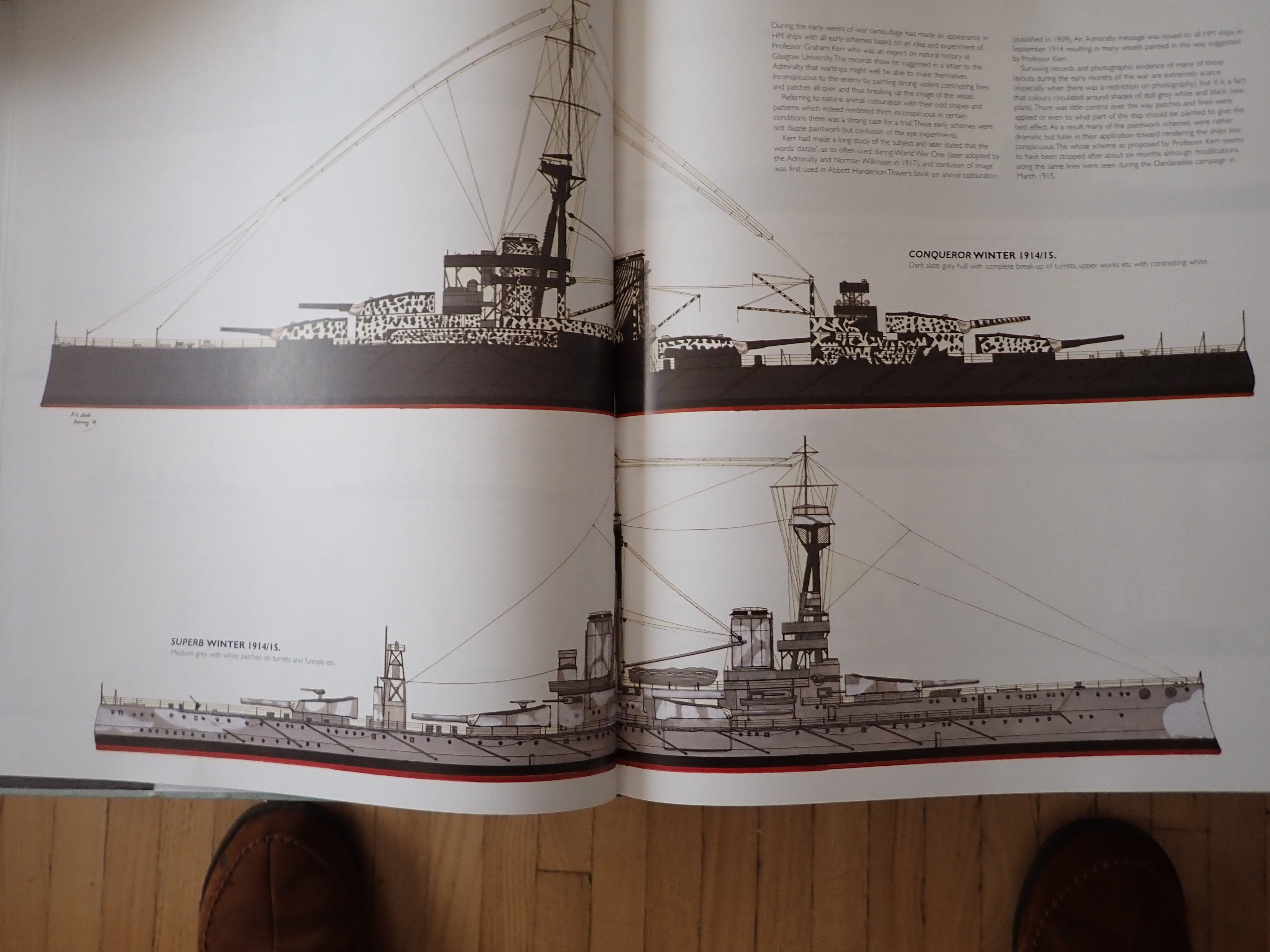
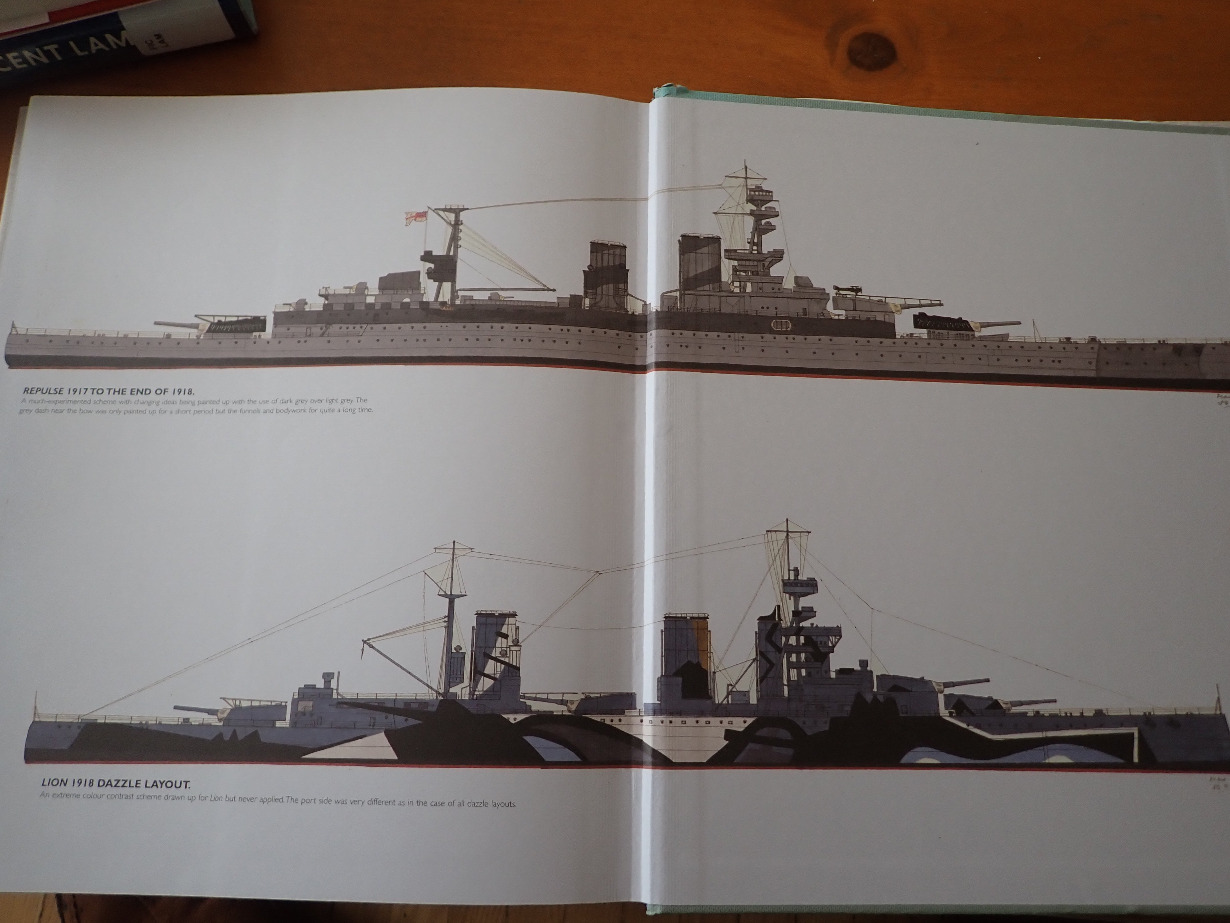
Received my copy of "British Battleships of World War One" which is quite interesting. It lists the naval estimates for each year from 1905, has many drawings and photos of each class, and gives detailed information about armour belt spans and thicknesses, armament, and most usefully a chronological list of modifications made in the course of the war. So in fact, I'd like to add the 1916 searchlight towers to Lion, but I also want to keep the torpedo net booms which were removed by then. Thus I may not be historically accurate.
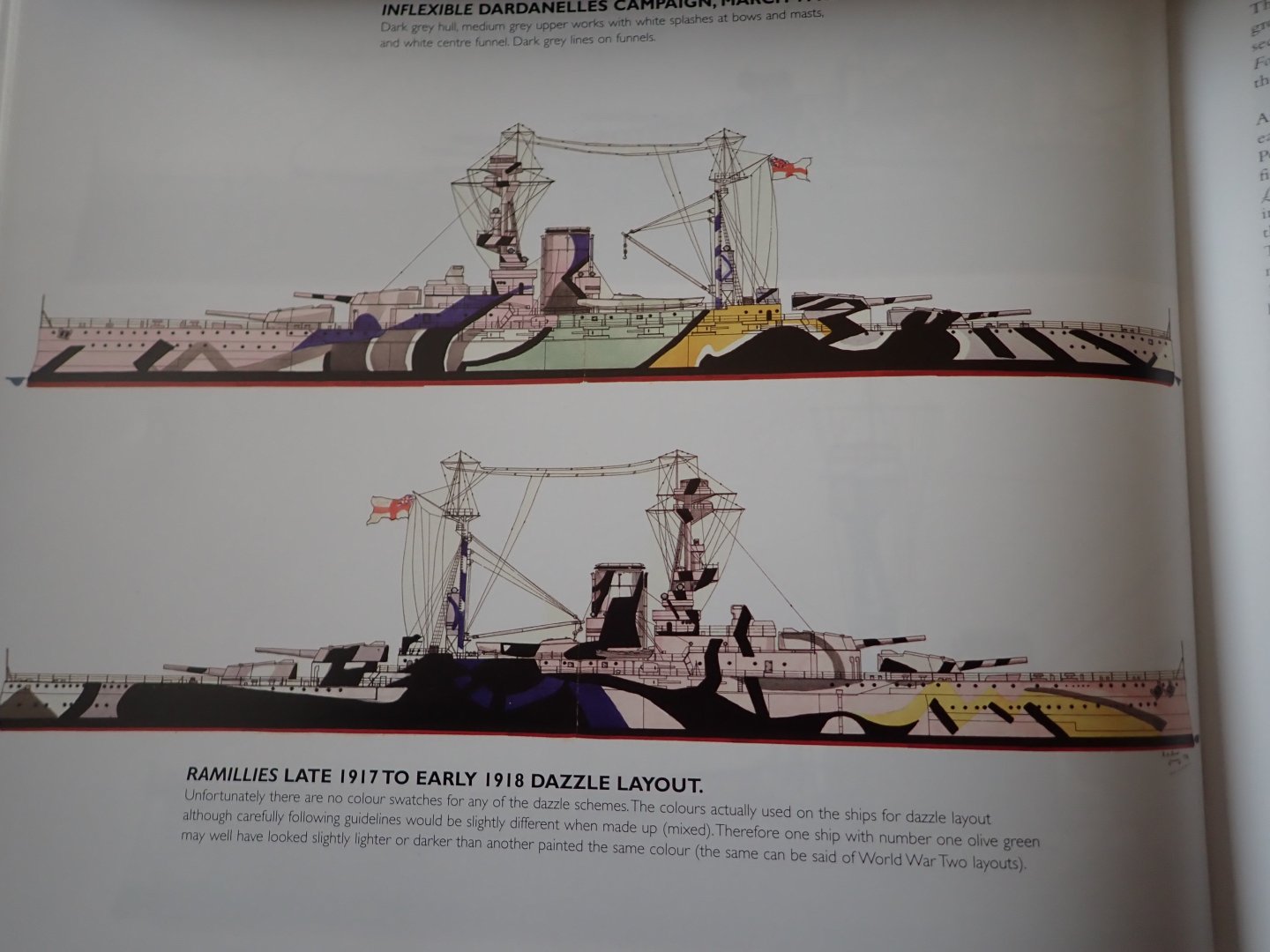
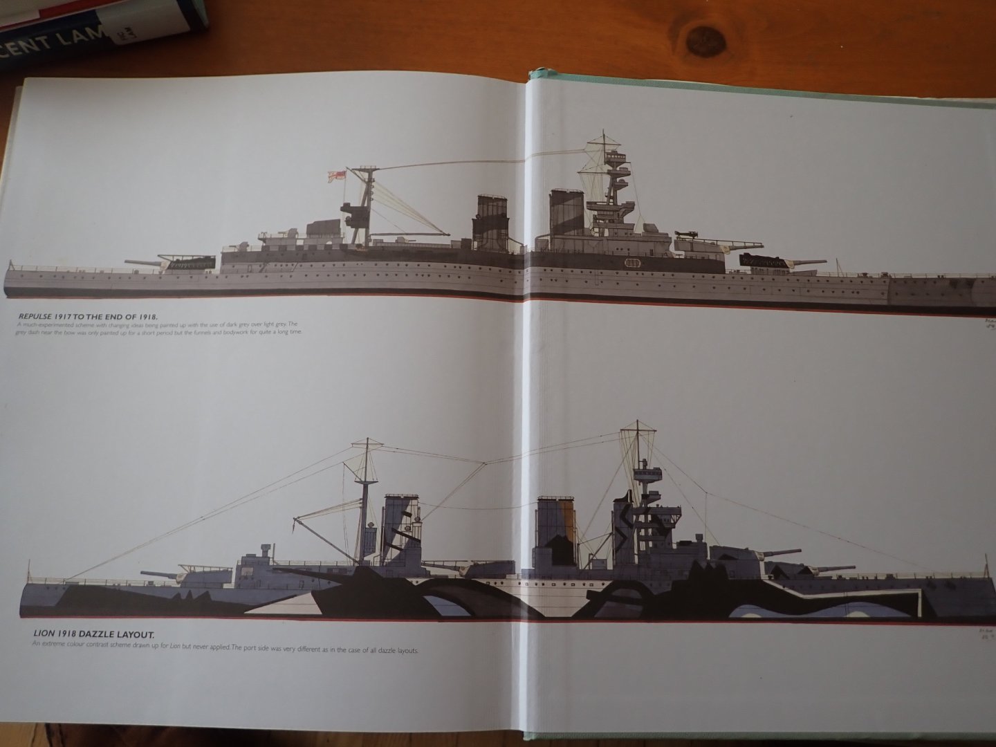
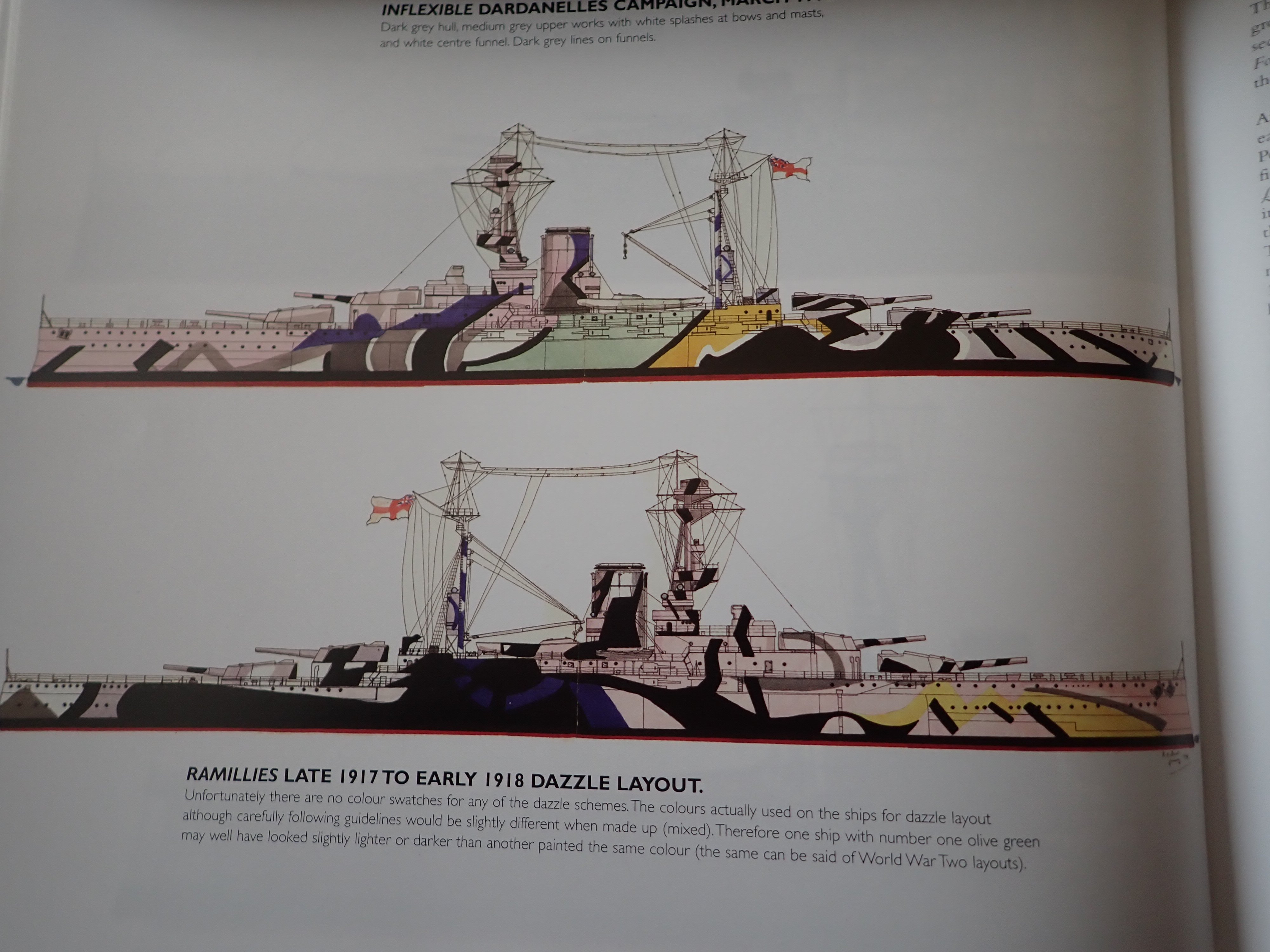
The book also has colour drawings of various dazzle patterns which were tried out on various ships. Many of them are pretty wild.
Still waiting for a second book I ordered.

- Colin B, GrandpaPhil, FreekS and 6 others
-
9
-
What about carving a half-hull, then cross-cutting it at intervals to reveal the frame shapes? I did that for the bow and stern of my Roman Galley and it worked out quite well.
- mtaylor and Keith Black
-
2
-
3 hours ago, Thukydides said:
Welcome Nick
You should still do one. It is the best way to get help as you go along. I also personally found the practice of documenting my build kept me motivated when I got bogged down in the middle. The help and feedback I got on my log made my first model way better than it ever could have been had I just done it on my own.
Good luck.
Thukydides is right. You will get all kinds of help from other members if you log it.
- Thukydides, mtaylor and Keith Black
-
3
-
Great kit, though formidable. All the best for this kit, and hoping to see a build log! (Go Habs Go!!!)
- mtaylor and Keith Black
-
2
-
Glen, you're doing a fine job on the rigging but (you can ignore me if you wish) your bowsprit bobstays look undersized to me. They're usually heftier rope than the martingales.
Just sayin' 🤫
Ian
- Glen McGuire, Keith Black and Canute
-
2
-
 1
1
-
Glen, I'm late to this party too. Thanks for the heads-up! You're doing a bang-up job so far and it's wonderful you are doing it for a family's memories.
Looking forward to seeing you decode more rigging jargon. Now you know how Bill97 felt trying to rig his Victory using Longridge's book. 😉
- Keith Black, FriedClams, tmj and 1 other
-
4
-
Glen, I'm a little late here, but I'm happy to see you off on another imaginative build. Looks great so far!
Nice to see the RR track put to use again. Must get some. They've been building light
rail lines in this town for years, creating many detours on the cycling paths.
-
1 hour ago, ddp said:
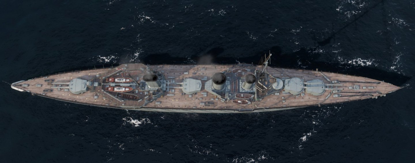
the Norman A. Ough's drawings shows the center funnel being round, correct? i think it should be oval like the aft funnel. you could cut a disk out of paper or whatever & place it where the center funnel is to see what the diameter dimensions do to the surrounding area.
No, Norman's drawings show it as oval. It's the Naval Encyclopedia's 3D render that has it round.
Thanks, I will omit the extra deck.
- Canute, mtaylor and Glen McGuire
-
3
-
Hello ddp; thanks for commenting!
You're right, as a teen I missed the two 4" gun casements on the forward shelter deck for some reason. They're on my drawings.
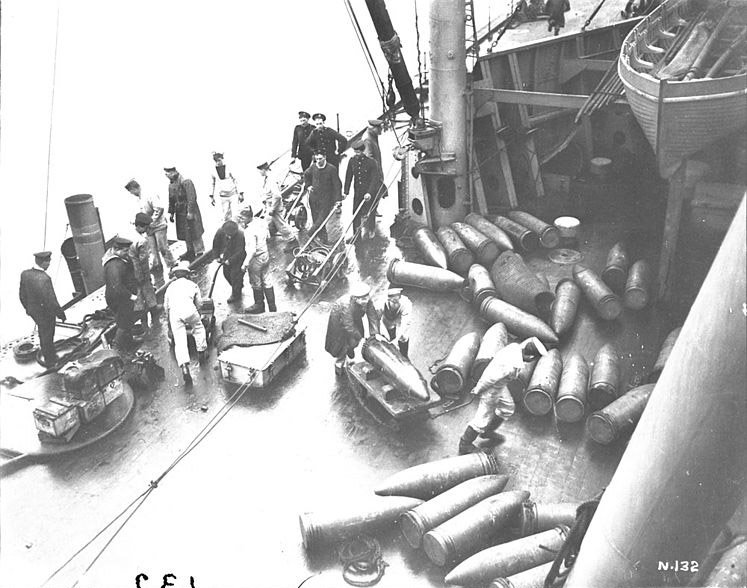
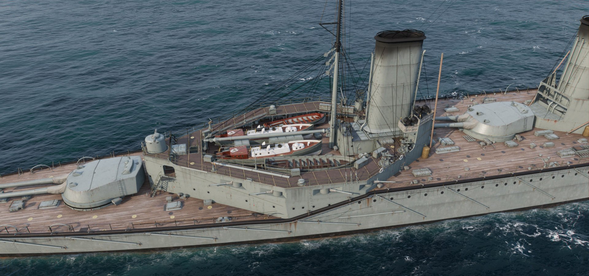
After looking over the drawings I think I will be building complete new superstructures. According to a 3D rendering in the Naval Encyclopedia the aft shelter deck is supported by posts around its inner edges leaving what is beneath it as an opening. Difficult to pick out in to tell in my drawing but now that I look again I see that it is so. The rendering also shows the aft SL towers added after 1916 but oddly still with smaller twin SL's instead of larger singles as I have seen in other drawings. On the other hand, this same 3D rendering shows four 4" guns on the weather deck level on the forward superstructure and an open shelter deck, as well as the central funnel being round not oval, so how much can I trust it? On yet another hand, it shows another deck between the two forward funnels with some boats stowed on it. My drawings show no such thing but there is a photo in the Naval Encyclopedia entry "Loading Shells Aboard 1917" which does show a boat stowed above the weather deck on some kind of beam but no deck.
I'm hoping for clarity when my two book orders arrive. ddp, it seems you may be familiar with this ship; can you comment on any of the above?
Yes the model is about 56" long.
As a teen I didn't worry too much about u/w details other than getting the hull lines correct. I think bilge keels would be too exposed and fragile for an R/C model which will be handled and carried around. The two props she does have are over-scale but again not visible when in water.
Rendering from the Naval Encyclopedia:

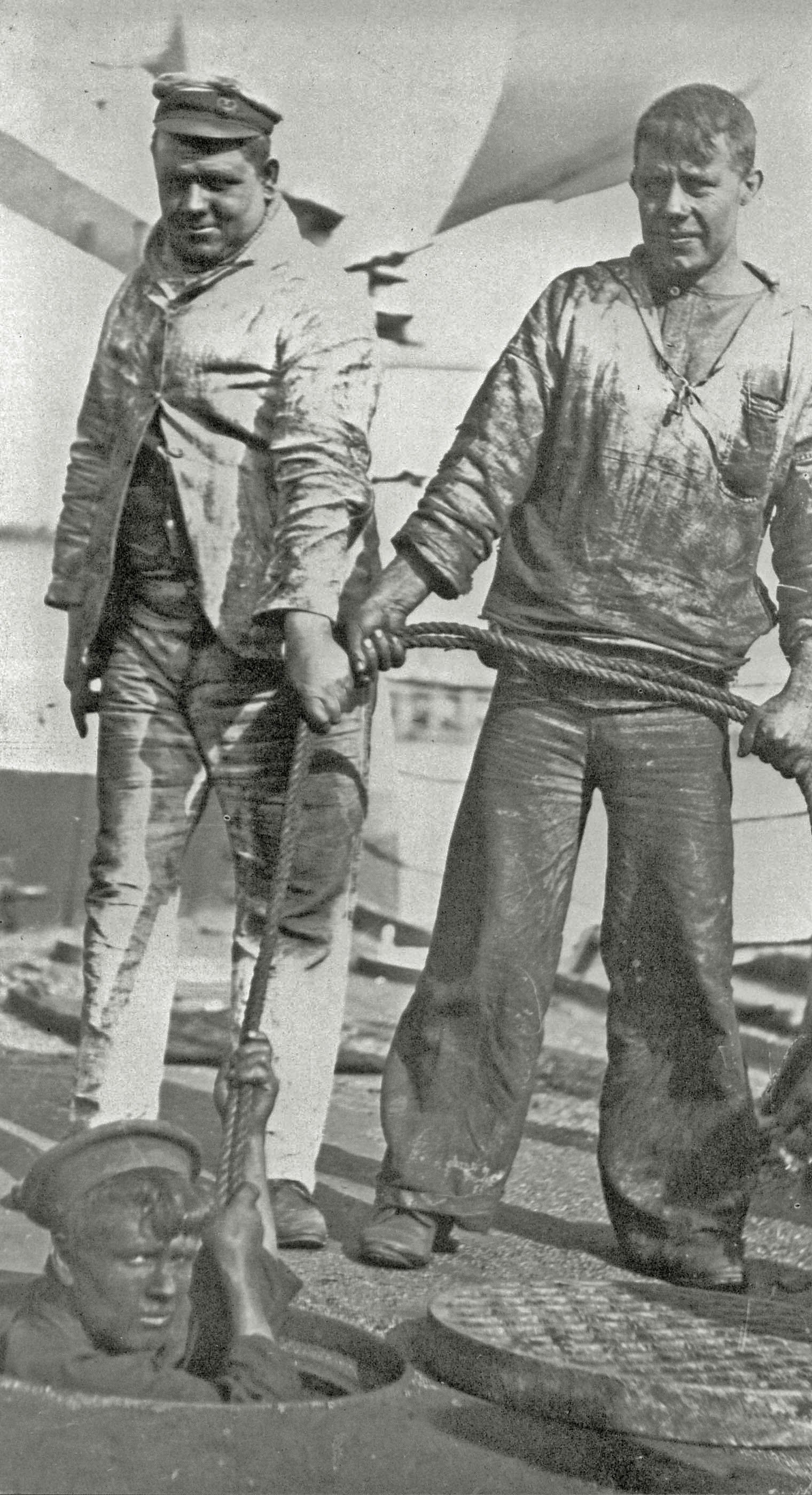
Loading shells 1917 - note the boat stowed high on beams. It's not stated which ship this is, Lion, Queen Mary, or Princess Royal, which all differed slightly.
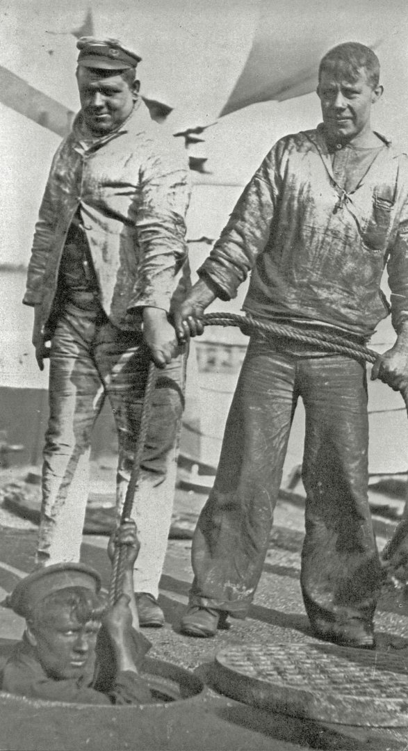
Coal scuttle - what a job! And no masks! I wondered what these actually looked like; they're exactly like manhole covers and are just small shaded circles on my drawing.
- yvesvidal, KeithAug, Glen McGuire and 4 others
-
7


Endeavour by Bill97 - FINISHED - OcCre - 1/54
in - Kit build logs for subjects built from 1751 - 1800
Posted
Good catch.