


Ian_Grant
-
Posts
1,667 -
Joined
-
Last visited
Content Type
Profiles
Forums
Gallery
Events
Posts posted by Ian_Grant
-
-
Yes. Have you seen the "Great Engineering" series at all? Very very good, ranging from constructing a 19th century offshore lighthouse on a wave-swept rock off Scotland, to building the "Great Eastern". Fascinating ship. I wouldn't mind making an RC model of her, complete with side paddlewheels and stern screw and masts too.
-
4 minutes ago, popeye2sea said:
SR was in that transition period when reefing was coming into vogue. As I briefly mentioned earlier, reefing begets footropes because of the way the sail has to be gathered and tied at the top of the yard where, with the former method, the sailors would be standing or sitting.
Henry
It's incredible to me that they worked that way .... I wonder about the attrition rate due to falls ...
-
Having a primary loop on the winch is the right approach for the drum type. Look forward to seeing your sea trial video in the spring. We will both have a new boat to debut.
-
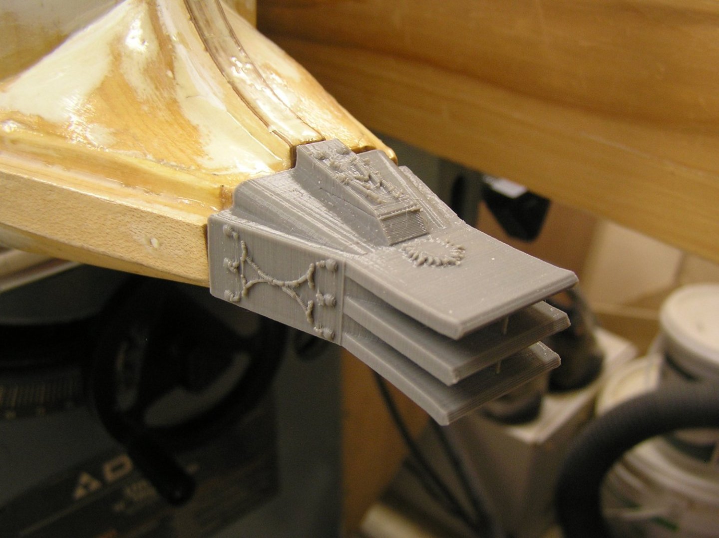
Printed the ram. It came out pretty good except for some of those curved decorations I added between the ball projections (I added some more of these to the design which are not in my TinkerCAD screen grab above). They started to fail because the printer was trying to deposit them on a slope, as I printed the whole thing standing up. I need another print anyway because as it turns out my pins projecting from the hull are not quite symmetric, and also I need to ask the Imagine Space staff about making the base part solid to allow me to use melt-in threaded brass inserts in order to attach the ram with a couple of set screws from below. This original print is all default settings, 0.2mm layer and 10% fill. I will take the opportunity to beef up those arc segments so they can print better, I hope.
I also started to clean up the deck beams by framing in the three removable deck areas (bow, stern, entire engine room). The stern framing is very heavy since this will form a handle for picking her up out of the water.


-
6 hours ago, Kevin-the-lubber said:
That’s really not bad going using TinkerCAD. I think all CAD is quite difficult at first and that quite an advanced shape. I hope the print comes out well, I imagine it’s a filament printer so you’ll at least get a nice, strong ram.
Yes, that tapered base with rounded corners is a mess of tilted cylinders and planes. I cannot figure out how to remove, say, an unwanted corner of a plane sticking out from the side of a cylinder. Maybe TinkerCAD lacks the complexity, or maybe it can be done but I don't know how.
We'll see about the print. I had to be at the library printer to get the print time estimate and while there we discussed what orientation to try. I want the decorative elements to be clean. If they come out a mess I may split it into three parts but hope not to have to go there.
1 hour ago, Bill97 said:Beautiful Ian. You guys doing your own 3D printing of parts are taking model building to a neighborhood I have never been too, nor does my GPS have any idea where it is! 😀
BIll, TinkerCAD is not too hard to use and as you see it can generate intricate shapes. You might want to look into the whole 3D thing and see if you have any access to a local printer. For example, Heller's "Preussen" has nonsensical kit ladders but my brother printed new ones for me from a TinkerCAD file I sent him. Handy for modelling!
- Glen McGuire, mtaylor and Bill97
-
 3
3
-
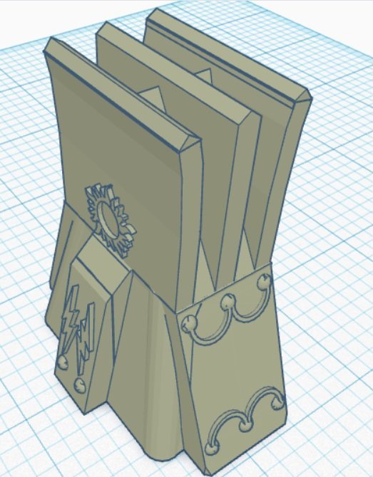
I used the library 3D printer to make a few test shapes to match the bow cross section where the ram meets it. The third try was pretty good. I then used the final shape as a base, and drew the rest of the ram. Being inexperienced with TinkerCAD this took me 1.5 days which seems ridiculous given the result, however if I had to do it again I'd be much faster knowing what I now know.
Here is the full ram. I decorated it using the shapes library. The top contains two lightning bolts where the stem enters the "casting" and I added a sun symbol on the top surface of the topmost fin. The machine predicts 2hrs43 minutes to print. Hoping for a good result. 🤞
-
On 10/16/2023 at 8:49 PM, Bill97 said:
Henry I like your narrative. I think I remember that narrative in Master and Commander.
Off topic but this reminded me .......
Remember the Aubrey book where Jack buys some gunpowder from a firecracker company going out of business, to use for great gun practice because the Admiralty doe not allot enough extra powder for training? He has Bonden and his gun crew demonstrate how fast a cannon can be reloaded and fired, but the gun crew is stopped in their tracks when the gun fires a great cloud of brightly coloured smoke with an unusual bang? Then they go down the side firing by turns, in green, blue, red, etc, with the onlooking crew in stitches? One of the great scenes O'Brien made up. One of my other favourites is the time at Sunday Divisions when Jack is pacing before the ranks of the crew for inspection, with the bosun's cat pacing in front of him.
-
Kevin, you and I are on the same voyage of discovery, realizing just how laser cutters can simplify model-making! Will enjoy seeing what you do with it .....
Regards,
Ian
-
19 hours ago, Keith_W said:
This has to be one of the more incredible build logs on MSW. With most of the other logs, the focus is on research and craftsmanship. With your log, it's also about engineering and getting the project to work. I can't imagine myself ever acquiring the skills to do what you have done.
Keith, that's high praise indeed, thank you very much! I made electric RC boats in my teens, had no time for decades, wanted to get back into it but do something unique. This will be great looking on the water but will be a bear to get there. Long, wide, and heavy. And where to store in winter? I may have to sell it.
10 hours ago, Bill97 said:Ian the RC model boat group sounds fun. Not only do you need to build a beautiful ship, you need to make it float and move. As Marc has made very clear in his modification of the Soleil Royal kit. There is no way it would not tip over based on the shape of the hull. Luckily I don’t have to worry about that.
Actually BIll people do build RC models of such ships. The secret is to have a relatively long fin keel amidships with a lead bulb ballast on the end to "stiffen" the ship. When this galley is done, and "Preussen" is finished, I would like to build an RC square rigger; not a warship with cannons but something along the lines of a windjammer. Here is a link to a very informative and interesting site about Mr. Neville Wade's fleet of such ships. I would like to build something like his "Judith Kate" based on the actual ship "Herzogin Cecile" which ran aground off Devon in 1935 under a new captain who had replaced a highly experienced captain who retired. Apparently she had just arrived to the UK and was veering inshore to receive signalled orders when she hit a rock. Of interest is that the owner, Gustav Erikson, dismissed the new captain for losing his favourite ship even though the captain was as I recall a relative. He ended up farming sheep in South Africa!
-
Thanks Bill; it's been quite a saga but now that the finishing stages have arrived I'm really looking forward to painting it up nice. I joined the local RC model boat group; apart from monthly meetings in the winter, I think they usually have one session at a local indoor pool. I'm hoping to be ready for that evening.
-
On 9/26/2023 at 1:18 AM, Louie da fly said:
Hi Ian,
The height of the oarholes above water don't look excessive at all, but it was the heights at bow and stern that seemed a bit much. However, so far I haven't seen the full midships height once the superstructure is on so I don't have an idea of how it will look when that is added.
Good luck with those rudders! Your 'disguise' idea might be the only workable answer.
Anyway, looking good.
Steven
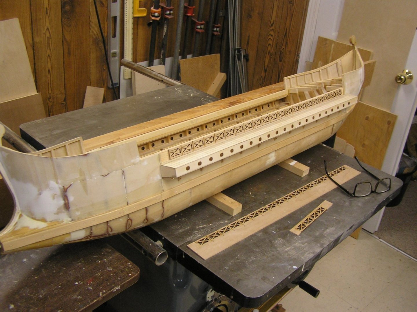
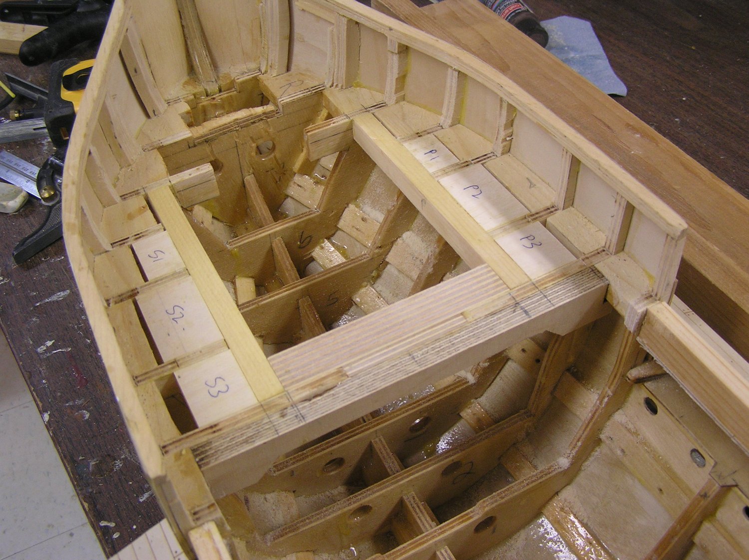
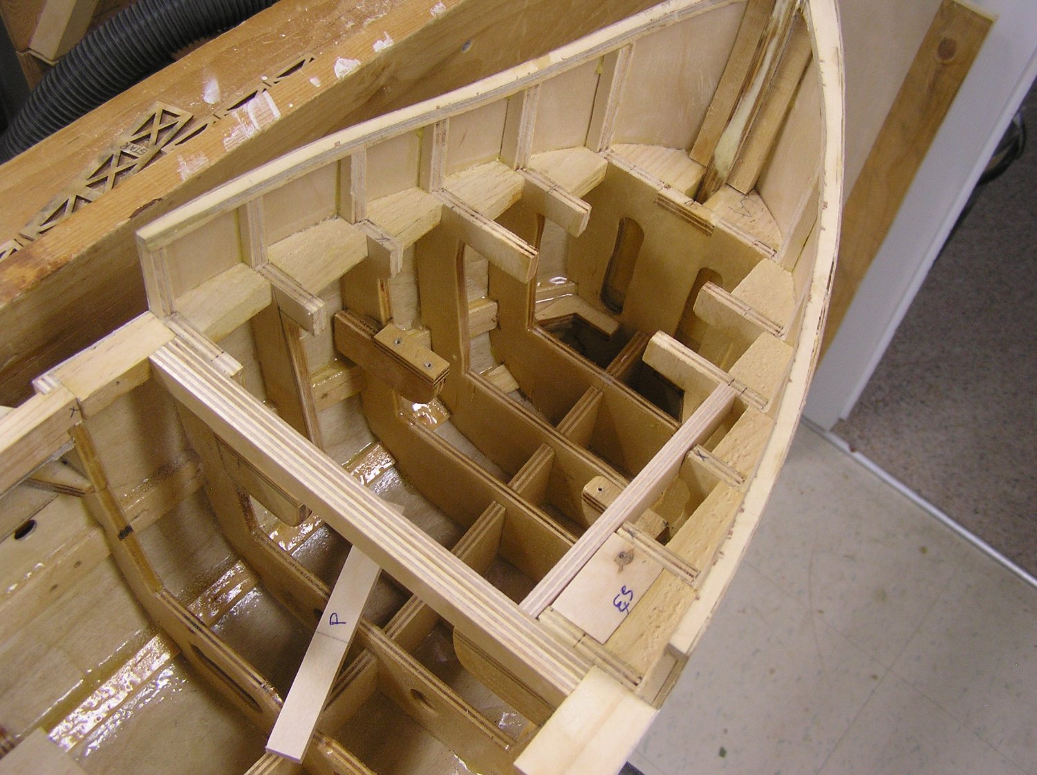
I'm building up the hull sides above the outrigger so we can now see how the hull looks with wood added to deck level. I think it looks proportional. My one doubt is that I began the upsweep of the bow bulwarks too early; I may revisit the curve though it will be painful to cut off my painstakingly laminated false top rails.
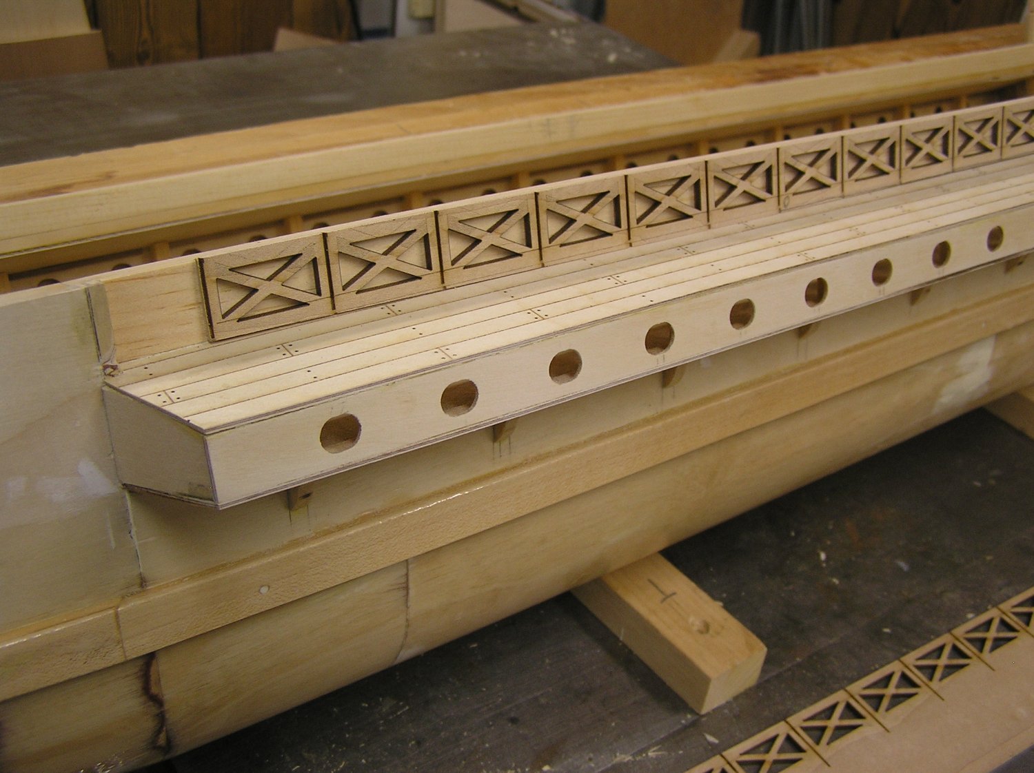
Here are some pics. I used the library's laser cutter (60W Epilog Mini) to etch some planking for the outrigger tops. My mind is opening to the possibilities of this machine. I didn't want to form all the "X" shapes in the ventilation course with bits of wood; thought I might 3D print it in sections; finally used the laser to cut them out. I ordered some decorative brass strips from Etsy to dress up the hull but now I'm wondering if I could just laser etch patterns.
The ventilation is lasered out of 1/8" cherry and will be painted white. The pine wood behind will be painted black to simulate openings into the hull. I'm wondering how to finish the planking; spar varnish would look like a bowling alley lane. I'm reluctant to use water-based because it will bring up the plywood skin's grain and I don't want to sand much and perhaps damage the etching. Also pondering dry-brushing another colour on the planks for some aging. Does anyone have any ideas?

-
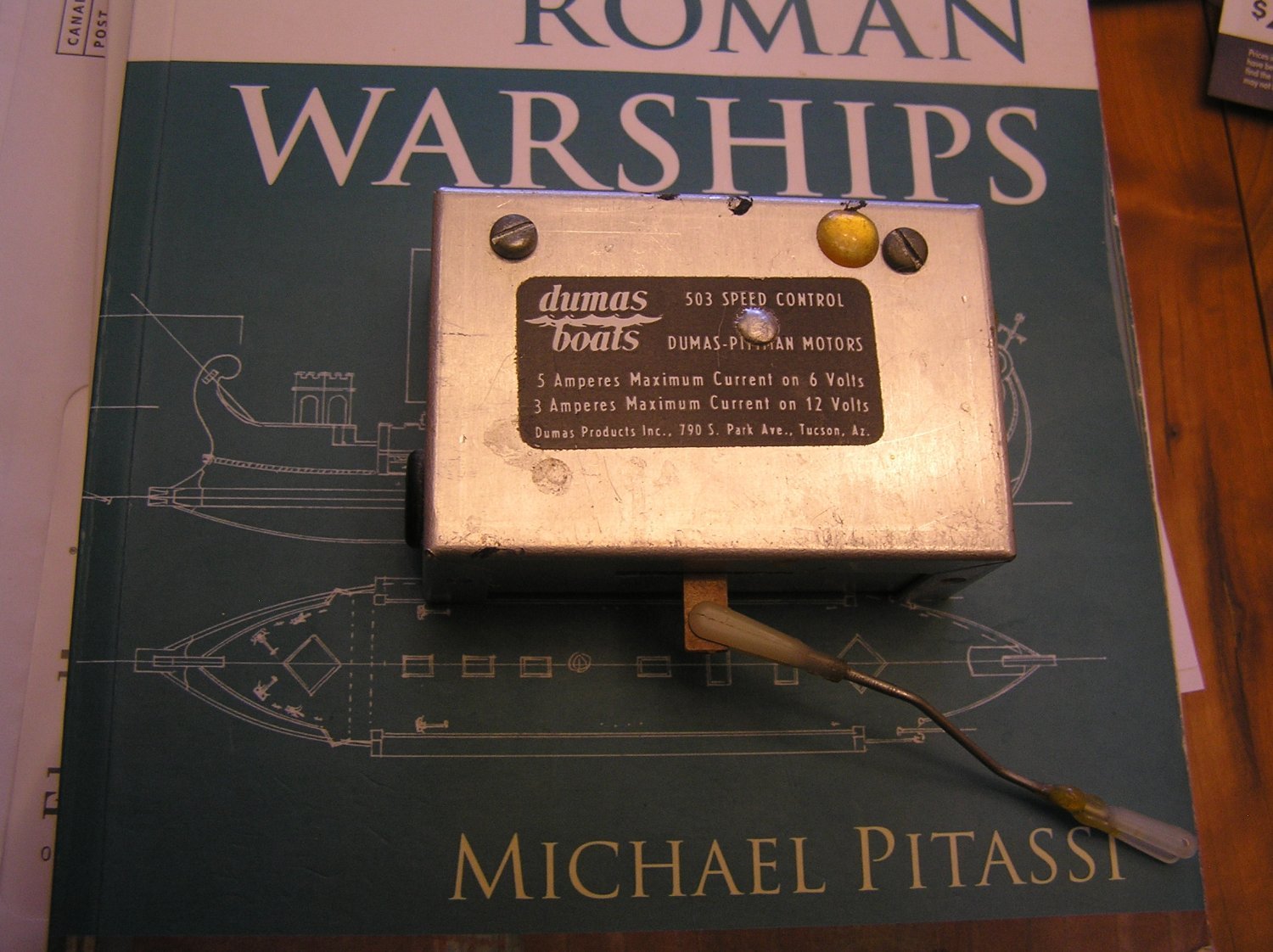
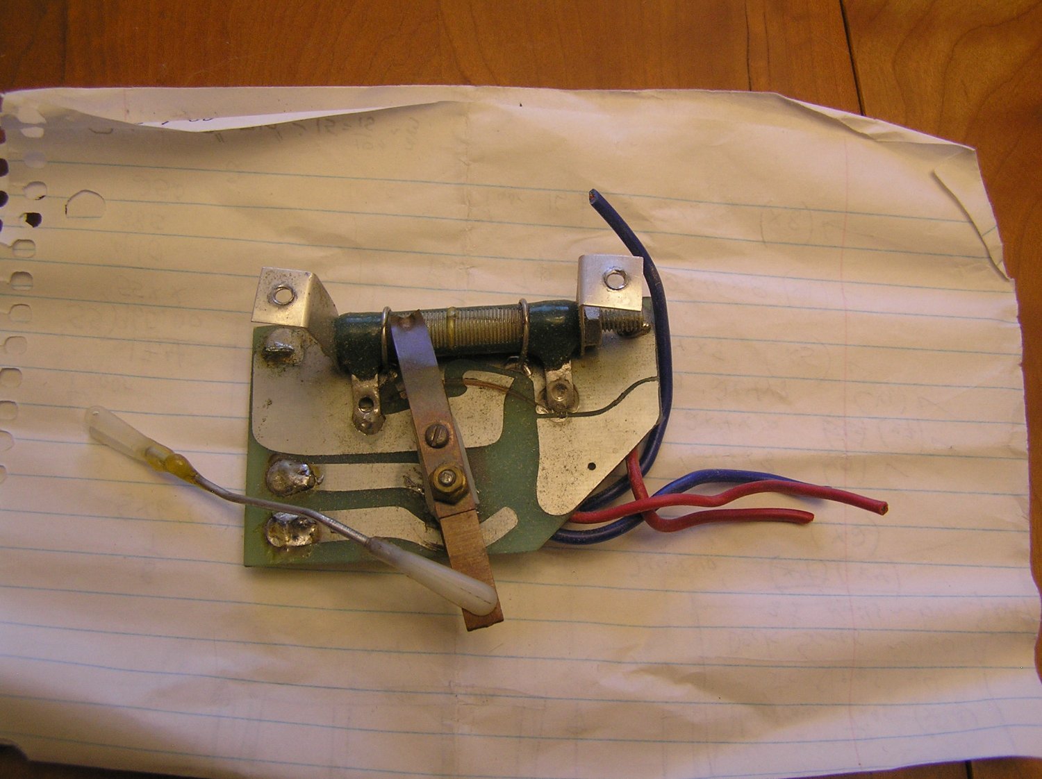
Back in the 70's I was into RC boats. Here is an old Dumas speed controller, with proportional forward, stop, reverse (complete with a blob of epoxy from almost 50 years ago!). I remember dismantling it to clean the exposed element in the wire-wound ceramic resistor, and the contact arm, to keep current flow steady. What wasted power in the resistor! As I mentioned you had to have a throttle servo to run it, unlike today's ESC's plugging directly into the Receiver.
I pity my kids who'll have to sort through all my old hobby junk when I'm gone. Or maybe I will one day dispose of stuff to ease their load. I seem to recall there's an apple basket somewhere full of old 0.049 airplane engines and parts, and I also have two 0.35 Enya engines which the hobby shop tells me are worth zero now. He did say the 0.049 engines are in demand though! 🤔
Fond memories .............


-
Especially at this scale !!!!

- Jeff T, Nirvana, Hubac's Historian and 1 other
-
4
-
2 hours ago, Bill97 said:
Wow Ian would love to see photos of your Galley. It really sounds pretty cool!
There are several videos in my rather long build log; those at the start showing the process of refining the oar mechanism and writing software for it, while the last two or three are sea trials in the pool. Now I am satisfied it will work I am working on finishing, painting, and decorating the hull.
Below is the build log. I got through about 5 pages before even starting to build a ship. 😊🙄
The most recent video is here:
- Bill97, Keith_W and Hubac's Historian
-
1
-
 2
2
-
26 minutes ago, Bill97 said:
Thanks Ian. I will always say your help and guidance on the Victory has been my foundation for this build. Am I correct that you have the Heller Soleli Royal in your stash for a future build? Will be anxious to see what you do with it.
Yes, I have an SR in my stash. I was going to build it after the "Preussen" but that build stalled when I became distracted for the past two years by my Radio-Controlled Roman Galley; designing and refining an oar drive mechanism, writing Arduino software for it, and for the past six months designing and building the hull, culminating in "sea trials" where I had it rowing around our pool. Now that I know it works I am starting to complete and pretty-up the hull. I can even laser-etch decking boards using our library's laser cutter, and the more I use it the more possibilities open up before me .... it's an amazing machine!
Will also be using the library's 3D printer to print a ram for the bow, once I draw it in CAD.
-
Looking really great, Bill. Bow is already looking intricate with some of the head rigging done. Gunport lids really nice too. Nice work!
-
Yes, modern ESC's are vastly superior to the old big clunky rheostatic speed controllers used in the 70's, which needed a servo to move their control arm and wasted a lot of battery power. And remember cleaning their contacts? 🙄
Re fiberglassing - when I made my cedar strip canoe I had an ultra smooth sanded cedar hull which became lumpy plastic after three coats fiberglass resin with cloth. It was a letdown but it comes up beautifully with sanding. Even the guy who wrote the how-to book ("Canoecraft") wrote not to be discouraged when you first see the dried resin. HaHa.
Going to be a great model. Looking forward to seeing the painted hull!
- Ras Ambrioso and robdurant
-
2
-
On 10/5/2023 at 9:42 PM, Bill97 said:
<snip .. snip>
Marc I rigged the parrels on my HMS Victory. Ian would not have allowed me to do otherwise. I do remember it being tricky to learn how to make them at the same time as rigging them.
HaHaHa!!!
-
Hi Kevin; Those are the buntlines for the (absent) course sail. As you say, without sails they are just tied off neatly in a representative location. Modellers do the same when going "bare poles", and sometimes do something similar for the bowlines.
Buntlines are used to pull the foot of a sail up when furling or reefing. At sea there would have been buntline blocks where they have them tied off and the buntlines would be spaced along the sail's foot.
Bowlines are used to pull the windward leech (side) of a square sail forward when beating to windward, They attach to the leech in two or three locations with a little "crowsfoot". Modellers without sails clinch them to the yard about where they would be with the sail furled but I think by Cutty Sark's day they were obsolete.
On Cutty Sark today, they also have those tidy-looking triple iron rings dangling in mid-air, representing the bottom corners of the course sails to which they tie off the sheet, the tack, and the leech lines.
-
-
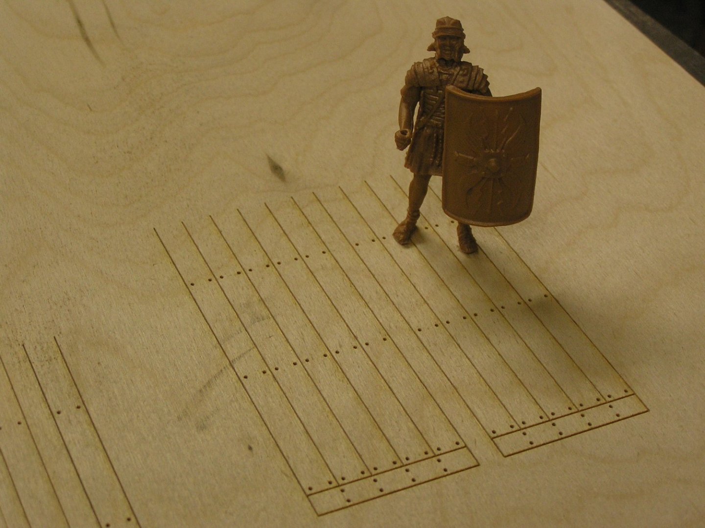
Was going to refrain from posting for a while, BUT I just went to the library and used the laser etcher to make some decking patterns for the two steering platforms, as a test of whether to do the same for the main deck too. I'm thrilled by the result. Going to "plank" the tops of the outriggers too now.
You can just see a few "test" planks at the left that were etched to select the raster speed for a good darkness level.
Marcus is thankful to have a good solid deck to stand on instead of water ...... 😏

-
Despite my previous comment, here is another short post.
Hadn't got around to stripping the interior parts until today. Before doing this, I borrowed a cat weigh scale from my wife's clinic.
Weight of hull/mechanisms/oars/servos/arduino (no battery) .......... 5.5 kg
Total lead ballast .......... 5.2 kg
Total displacement ...... 10.7 kg (!) you can see why carrying with a midships handle would be problematic...
*************************************************************************************************************************
In post #127 I estimated hull + mechanisms would be 7.9 kg. That was before I thought of cutting the metal drawer slides shorter.
So the actual at 5.5 kg is about 30% less than estimated. Actually, a bit more because the 5.5 kg includes servos and all.
My estimated total displacement, with battery, was 8.34 kg.
I designed the hull to give me some extra displacement over and above this, which would be met using ballast.
I ended up with extra displacement of (10.7 - 8.34)/8.34 = 28% .
Given that it's still a little sensitive to ballast distribution I wouldn't want to reduce it, so no hull re-work is I think the correct call.
So the overall result is not bad. If I did rebuild the hull, I'd just be losing ballast and maybe it would be too tippy.
Thanks for following. Toodle-ooh!
-
All the way to the keel, Bill.
-
6 hours ago, John Ott said:
Nice furniture, light walls, wood floor, no carpet, nice, well-lit corner. No clutter, everything necessary in easy reach. A great setting for building and rigging a great model.
Of course you know you're making the rest of us look bad.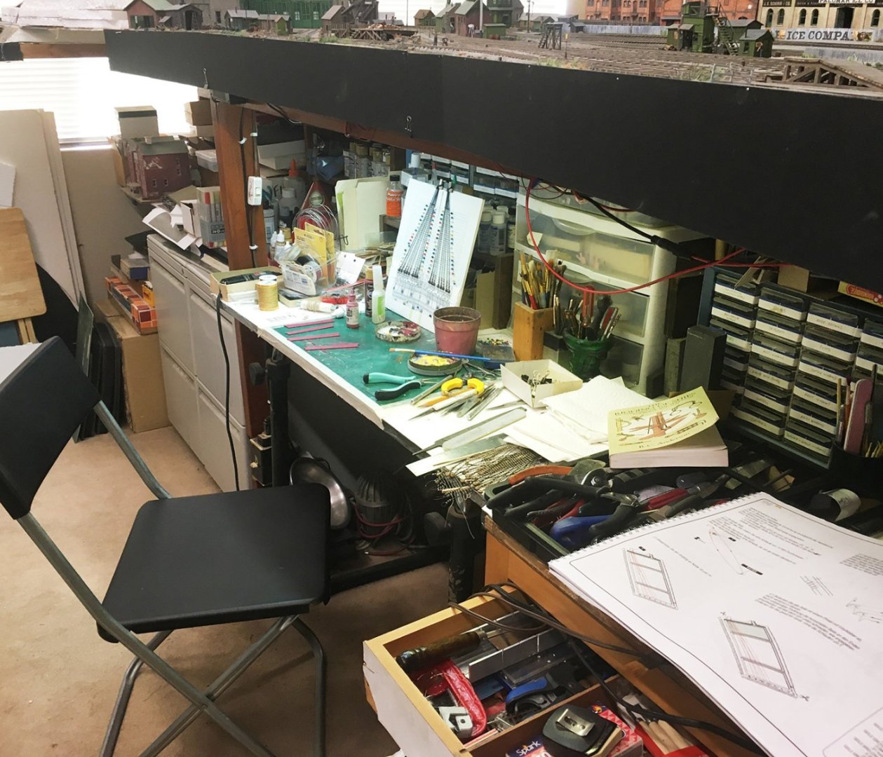
John, I see a train layout there; how extensive is it? I've seen setups that run around the entire room.


Le Soleil Royal by Bill97 - FINISHED - Heller - 1/100
in - Kit build logs for subjects built from 1501 - 1750
Posted · Edited by Ian_Grant
I can't seem to find it. TVO broadcast it a couple of years ago; I thought it was on the "Impossible Engineering" series but googling that did not reveal an episode on this ship. There are, though, some interesting youtube videos on her.