


Ian_Grant
-
Posts
1,667 -
Joined
-
Last visited
Content Type
Profiles
Forums
Gallery
Events
Posts posted by Ian_Grant
-
-
-
Tomorrow I will be taking the mechanisms, electronics, and ballast out of the hull to return to just working on a wooden ship.
Changes I have in mind for the mechanisms include:
1) Have vertical mounting slots for the upper oar beams to facilitate adjustment relative to the lower beams.
2) Since I will not have the central handle, move the lift servos closer to midships to reduce the disparity between the link lengths to each end, and move the servo mounts slightly closer to the keel line to allow slightly longer servo arms to be used.
3) Cut a notch in the u-channel where the bellcranks are mounted to allow them to tilt further down. This change combined with the longer lift servo arms will give a greater range of lift movement which I think I need to keep oars well out of water during return strokes. The existing range of movement barely meets the theoretical requirement from the oar geometry drawing. I can use the Arduino "Map" command to select whatever sub-range I want, later.
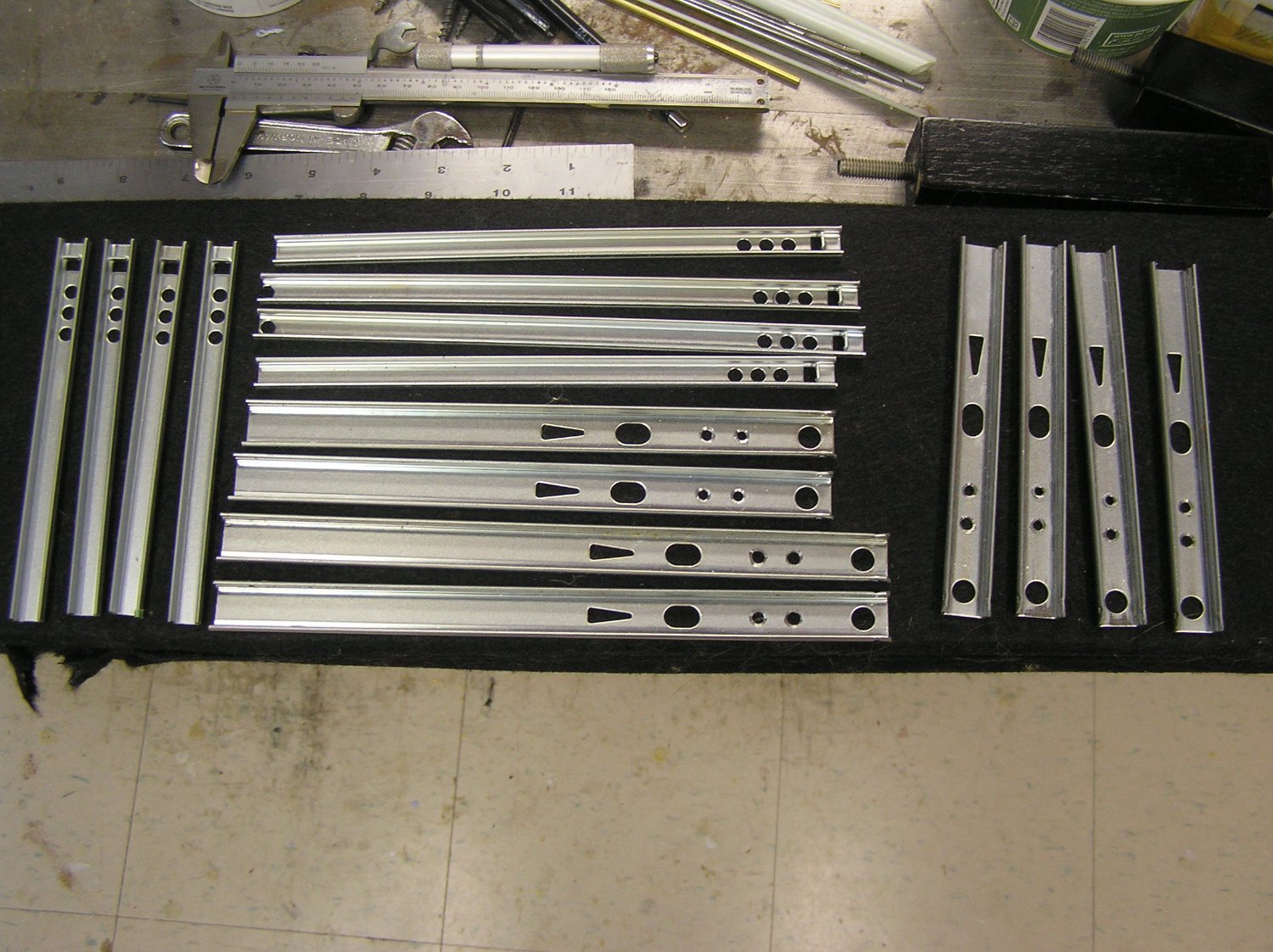
I rejected the idea of tearing the hull apart to change the bilge shape, so I will just have to live with the weight of the thing. One factor contributing to the amount of ballast is that I thought of cutting off the excess ends of the drawer slides well after designing the bilge curve. As a historical footnote, here is a pic of the metal thus removed. A not inconsiderable weight....
I probably won't be posting for a while, until I have some meaningful work done on the hull, but I will enjoy reading all your build logs.
Thanks for following this build. More later.

- mtaylor, Hubac's Historian, Bedford and 3 others
-
 6
6
-
Thanks Steven; Draw a level bulwark between bow and stern bulwarks and that's the hull.
Perhaps you are right. I'll consider it over the winter. I do see that my bow and stern bulwarks sweep up earlier than for example those in the gentleman's ship in #335; they could be reworked.
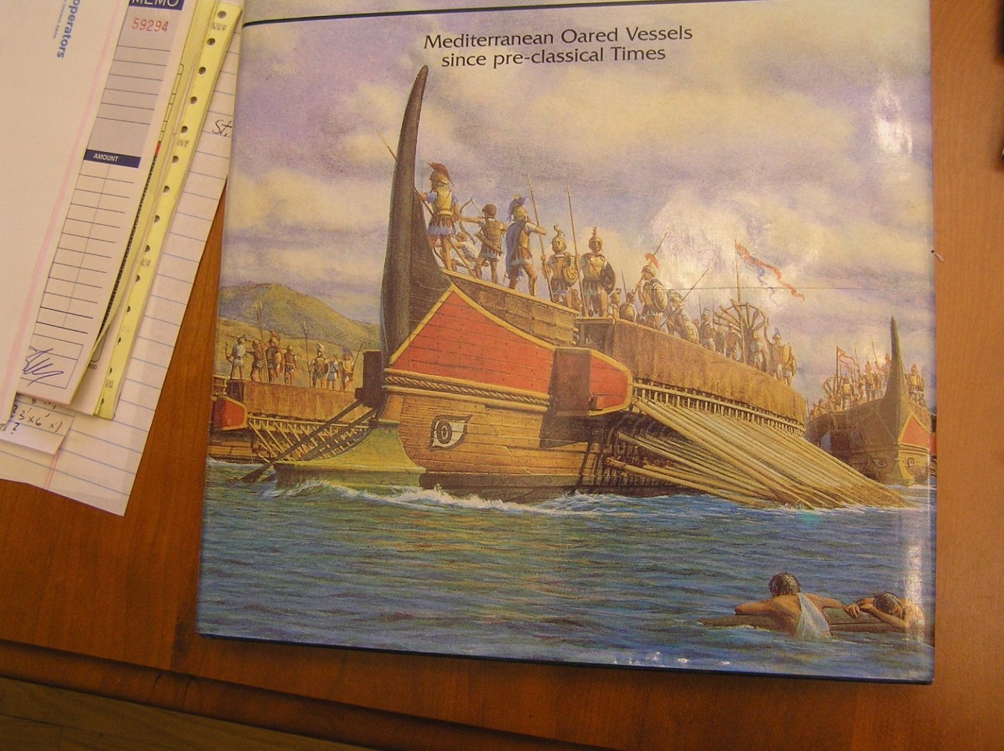
Consider the following pic from the cover of Conway's book on galleys. This Greek ship is pretty tall even without bulwarks.....
-
On 9/22/2023 at 8:40 PM, BANYAN said:
Thanks for your response Ian; your response highlights that I may not have been as clear as I should in my wording. I think your answer was definitive, but just in case, what I tried to say, was that while two oars are fitted, only one was typically used at time? From your response though I gather that both oars were either united or manned? Just interested
")
cheers
Pat
Pat - Yes both oars were used. In fact, on Hellenic triremes such as "Olympias" a single helmsman handles both, one tiller in each hand, one hand going forward and the other back depending on which way she is turning. Roman quadriremes were bigger and wider, requiring two helmsmen. See the fantastically beautiful, manned, model quinquereme in the video below (I'm hoping to paint and decorate my ship much like his although I have no actual planking to leave "natural" coloured). 🤞 At time 11:17 the two helmsmen are clearly seen, even wearing green and red to delineate their side, HaHa!
https://www.youtube.com/watch?v=bLiGM6MOBL0
If interested, his completion video is here:
https://www.youtube.com/watch?v=LuYBk0znbB8&list=PLN8dHnRD0y61NWWulgdXo7fMLYSnjZ943&index=11
-
Hi Steven, thanks for taking the time to discuss the boat on water!
To your first point, yes it's true, I've been running it at full throttle, most of the time. More relaxed rowing is available; indeed I probably should reduce software variable "MSR" (Maximum Sweep Rate) and re-compile. All this is still in experimental/development stage. Everything is open. Except cutting the bottom off the hull and rebuilding it with smaller displacement (!); I've decided that I couldn't face the work involved.
You've put your finger on the classic RC "scale problem". Let's call this ship 1/30 for round values; scale oar blades would be 1/30 as long and 1/30 as wide, for a total of 1/900 actual area. My oar blades are ridiculous for the scale, but hey, we need some traction here! Model sailing ships have it worse - for scale factor "n" they end up with, as you say, 1/(n**3) the displacement for 1/(n**2) the sail area, meaning "n" times as much sail area for the displacement. Hence all the dagger keels with lead bulbs.
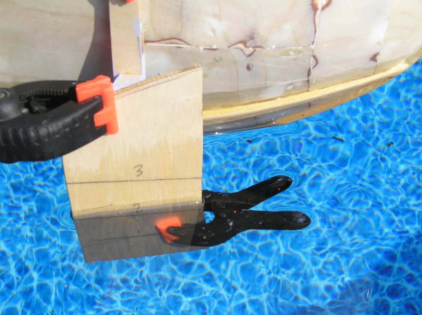
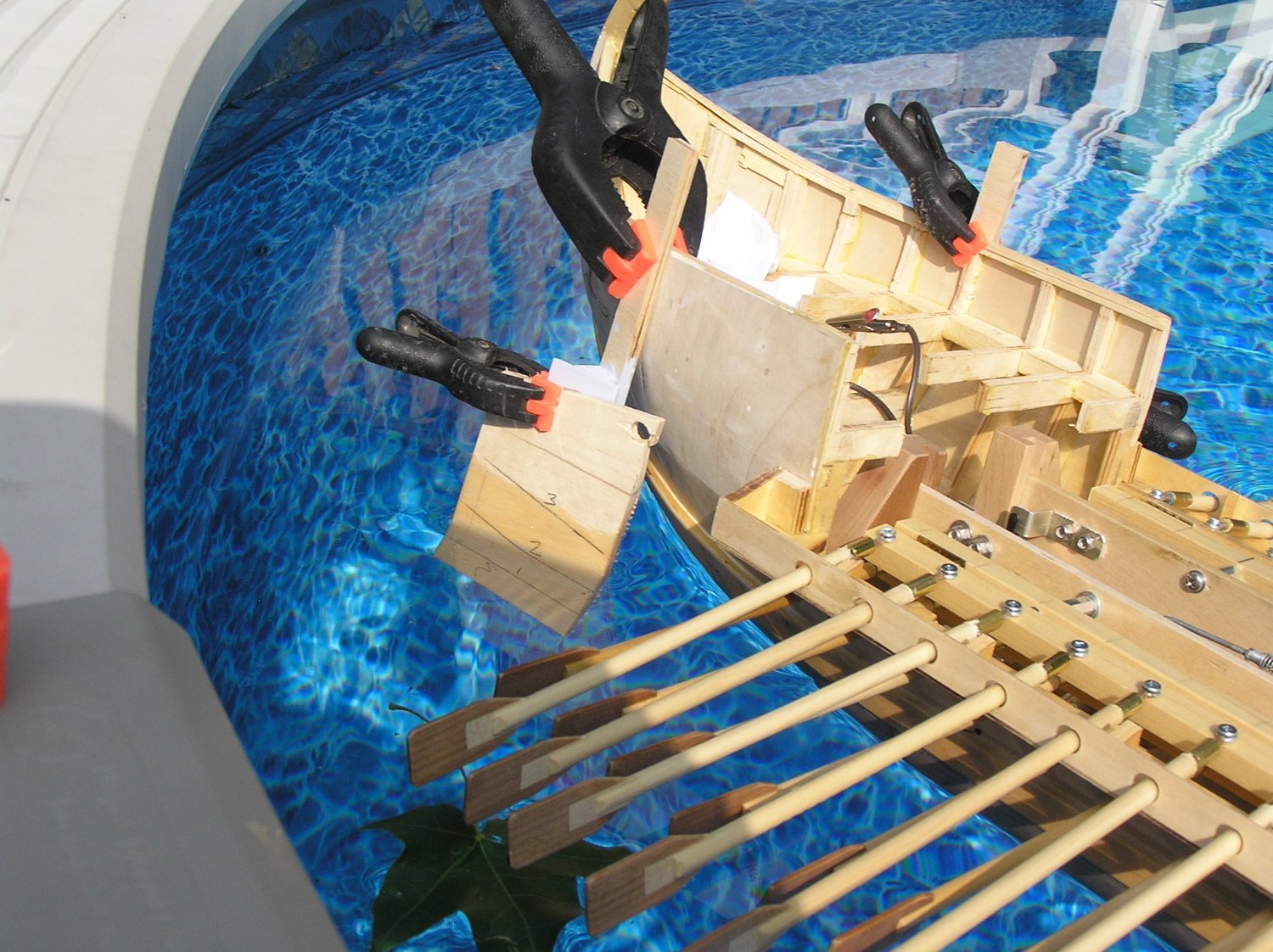
Over the weekend at the cottage I decided I **must** have some form of effective rudder control, even if it relies on stopping the inside oars (I'll save backstroking oars for emergencies; not sure they could even do it). I looked at my 30 degree dummy rudders, and when viewed from straight ahead the 1.25" wide blades presented an apparent 5/8" wide strip 2" long as resistance to the water. Now I see why they couldn't do much. To that end I played around today with larger blades clamped to my dummy rudders. With 2" x 3" blades I get pretty decent response. Two inches is as deep in the water as I want them to get; that's the limit for no rudder damage when sitting the boat on a flat surface with the resulting tilt because of the external keel. Three inches is wildly large. I will follow a convention I've seen in RC modelling mags where one paints a scale rudder on the over-large blade, then fills in the rest with black paint to "hide" the excess when in water. With that sort of dimension I may balance it a little too. Depends on aesthetics.
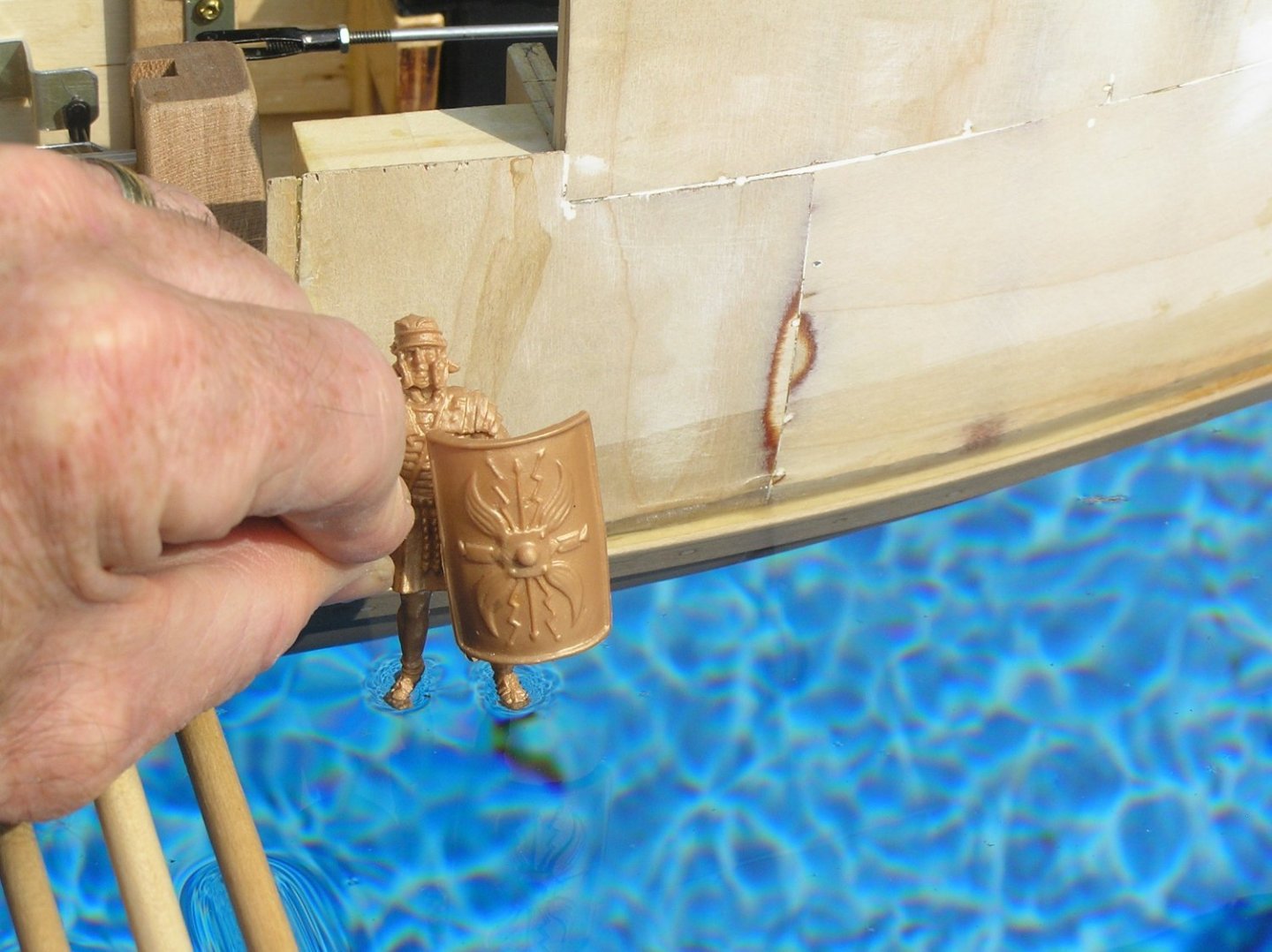
Regarding the height, yes my first drawing here looked like an overweight guppy. There are two factors (1) scale appearance would have the lower oar ports just 3/4" clear of water. I decided that was too risky so I added 1/2" for peace of mind (relatively). This extra 1/2" shifts everything up, obviously; and (2) the oar loom ends rise in the hull as the blades bite water. The deck beams must clear the oar mechanisms' beams when they hit their highest point. I reworked the oar geometry a couple of times with this in mind. Way back I reduced loom to 1.5" for this reason, but I had to change back to 2" for mechanical clearances when I decided to increase the outrigger projection to 1.25" because to my eye 3/4" was too paltry for the hull. In retrospect I could have lowered the deck somewhat by allowing for thinner beams, but I did not want the separate lift-off long deck to warp in future so decided 1/2" beams was the number. No one today really knows how tall these ships were; Pitassi quotes various classical sources and gives approx 10 feet as a quadrireme's deck height over WL. There's a pic below of "Marcus" standing on water by the break in the forward bulwark for boarding bridge deployment from the deck. Deck height looks fairly ok, even bearing in mind that Marcus is a scale 6'-2" giant of a Roman. 😏
One reason Olympias looks so low is that there are no bulwarks on the upper deck.
Here are pics of the giant rudders, and Marcus walking on water. Note, the real rudders won't be massive above waterline !!!

- Archi, Glen McGuire, Hubac's Historian and 2 others
-
4
-
 1
1
-
Bill, see Anderson pg 143 on lower yard parrels.
-
11 hours ago, BANYAN said:
Coming along well despite the set-backs Ian. An interesting video.
One small point, while I am unfamiliar with this period of history, many oar steered vessels only used a single oar at a time. Were these vessels using two? Perhaps a trial with a single oar may offer different effect?
cheers
Pat
Hi Pat; my Conway book of galleys has reproductions of ancient drawings showing Egyptian, Phoenician, and Hellenic galleys with twin steering oars. The trireme "Olympias", launched around 1990, had twins which were very effective as shown in videos available on youtube.
My Pitassi book on Roman galleys also shows them with twin steering oars, as gleaned from surviving stone relief carvings and even wall paintings uncovered in Pompeii. There's a place on my bucket list!
I realized that in the video, or maybe after it was shot, I had it rowing with oars on one side stopped (out of water) and it didn't turn much even then so my plan of shortening the inside stroke probably won't work. Maybe I'll have to put exaggeratedly large rudders on her after all. It will look awkward if I have to keep doing reverse strokes to steer.
- Glen McGuire, BANYAN and mtaylor
-
3
-
A day to remember - Sea Trial #3 with all 86 oars!!
My conclusions from this trial:
1) The upper oar blades hang lower than my geometry drawing, which is ok for power stroke but they nearly drag on the water during return stroke. Any slight ripple on the water will be a bother. Checking on the bench again, they do seem to be about 1/4" lower than planned. Will need to revisit the upper oar bars this winter and mount them again more carefully. Probably would be a good idea to change their mounting holes in the beam to vertical slots to allow adjustments on the fly. Would need to, I guess, find a 5/32" milling bit and use my drill press and some jigs. It probably doesn't help that I made those oars 1/2" longer....thinking I will take the extra length off, and make the lower oar blades the same slightly larger size, over the winter.
2) She is very sensitive to ballast amount and distribution, surprising me given her size and full, rounded bilge. Will need to adjust the whole ballast scheme when model is complete and final weight is known.
3) Realistically proportioned rudders have very little effect; there's no prop wash to apply force to them. I don't want hugely exaggerated rudders on the model so I'm wondering whether to even bother having them servo-controlled! Also, now considering rewriting the software, over the winter, to have the inside oars on a turn go to a shorter stroke, still in time with the outer oars as far as power/return goes. This would make her turn for sure. As rudder moves over more the inside stroke could get even shorter, at some point simply stopping out of the water, and going to reverse stroke at rudder hard over. Haven't thought about code but this sounds pretty complex to me since there would be different "delta-X" increments for the two sweep oars; plus we already have the new requirement of varying the sweep servo rotation rate to try to maintain a constant sweep velocity, as mentioned in a previous post.
4) She's damn heavy and awkward to carry through doorways. My initial scheme of having a central handle is an EPIC FAIL. 😭 You know that exercise where you have a dumb-bell in your hand and lift your arm straight out to the side .... that's what it would be like since you must keep the oars clear of your hip. 🙄 I'm now considering a very solidly built handle across the hull very near the stern, beneath the front edge of the fixed portion of the aft deck. One would grasp this and lift up stern first, then place other hand under the hull at mid-keel and carry it like a golf bag for example. Will be an interesting winter.
With all that, here is the video. Thanks to all for following me thus far!!!
- gjdale, Boccherini, Ryland Craze and 7 others
-
4
-
 1
1
-
5
-
Thanks, but they don't look heavy-duty to me, almost as thin as mine. I DID find some very sturdy 9v-connector-to-5mm-jack adapters in a music store, used to power up guitar pedals apparently. They were American made, thick and solid because a band can't afford to have them fall apart. I had a 9V battery with me and loved the solid feel of plugging and unplugging and I thought I had it solved. Unfortunately the standard in the music industry is that the jack is tip-negative whereas any Arduino is tip-positive in keeping with the electronics industry. I could buy one and cut the wires up but it's just one more joint to fail.
I ordered a thick-looking part on Amazon, made by "Pacific Science Supply", so we'll see how it is when it arrives.
-
Bill, as in their "Victory" kit, Heller did indeed omit any means of attaching the yards to the masts.
You have discovered the perennial problem with square rig - the shrouds limiting the swing of the yards which limits how near the ship can sail up to the wind. In the 19th century the clippers and windjammers employed iron "trusses" which held the yard forward of the mast and could swing the yard centres out off the ship's centreline thus allowing them to be braced up sharper.
In this case for these old ships I think they were just limited to staysails (the fore and aft ones) if they truly needed to get up into the wind (to claw off a lee shore, say). I suppose they could also loosen the parral to allow the yard to move forward of the mast, like they could loosen the truss pendants in later centuries, but I do not know if this was the practice in the 1600's.
-
Bill, she's looking very impressive! Good work, and keep going! 😉
-
Looking again at your beautiful pics, it occurs to me that the ESC fan could maybe use some duct for outside air on a hot day. Does the funnel actually ventilate the interior cavity? Note, I have zero experience with ESCs' as all my electric boats were made decades ago; simply circulating the interior air may be enough. You could check the ambient air max temp spec for the ESC and decide.
Looking forward to video of the maiden voyage! Great work!
-
-
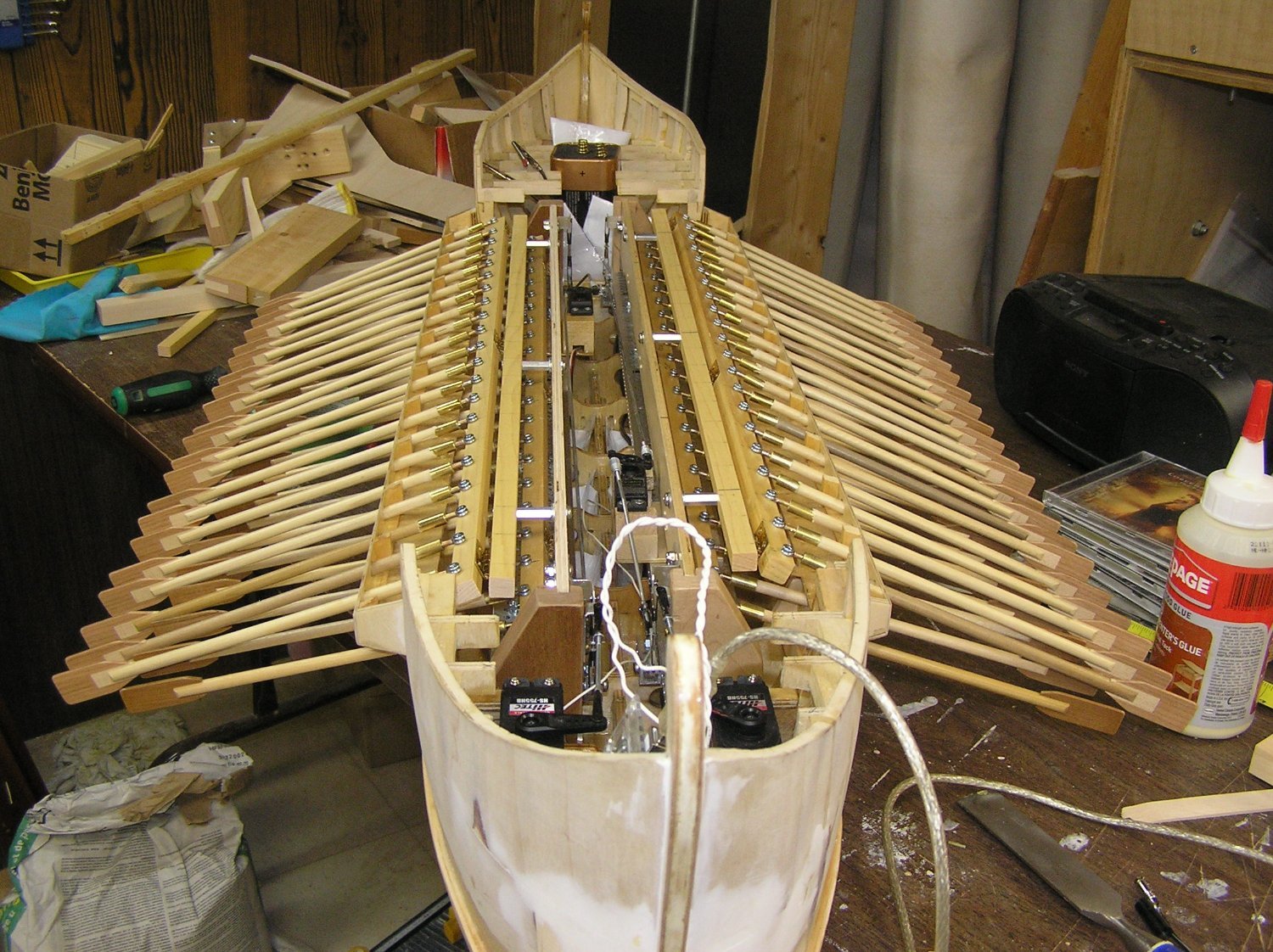
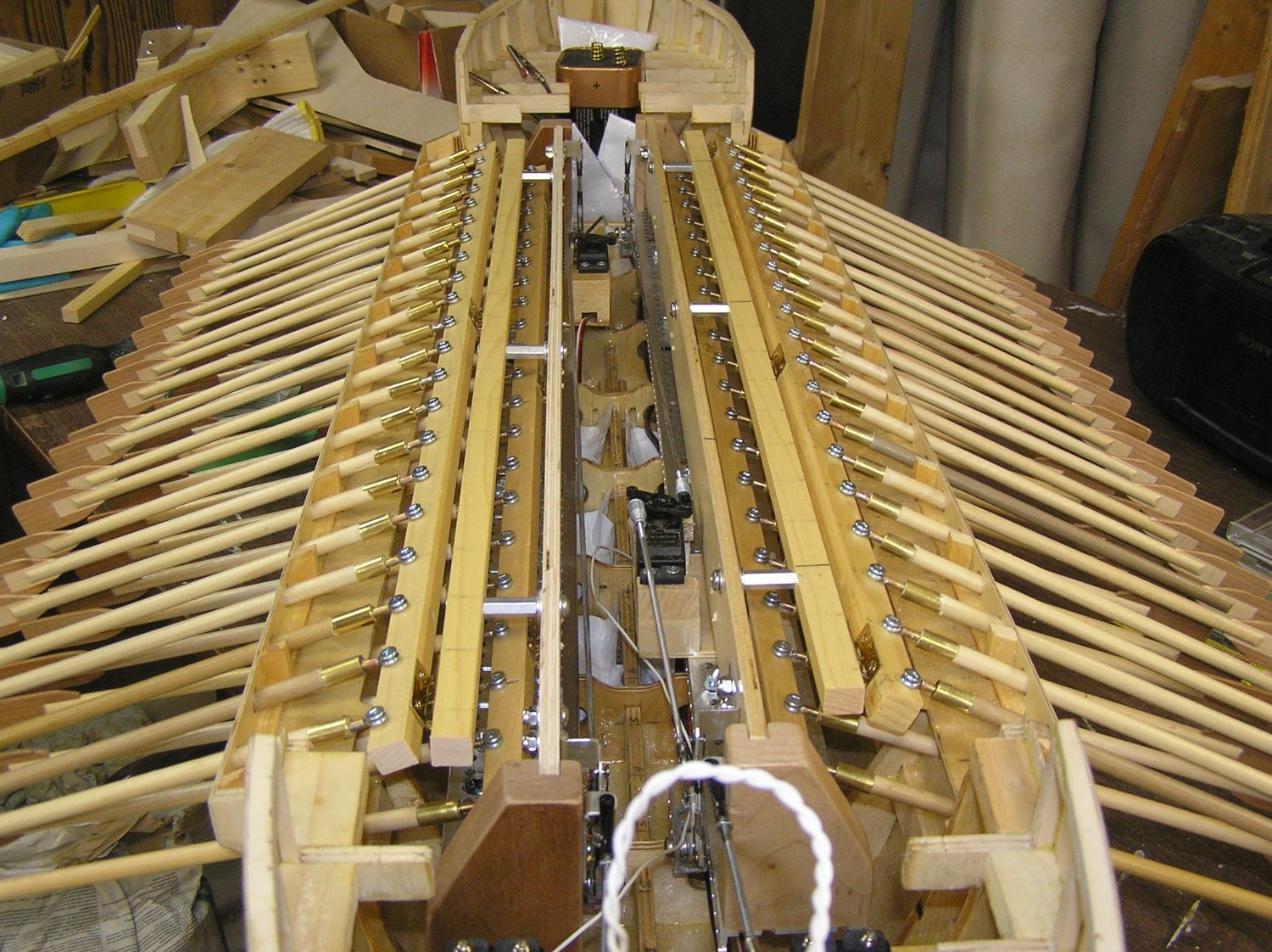
Added the upper pivoting oar bar to the starboard oar beam. She can now be seen in all her glory as an 86-oared vessel! Since I'm now using all the oar ports I fished the lamp cord I'm using for the battery connection through the bilges using the holes I had made in the bulkheads.


Too late today for a sea trial. In any case I ran into more 9V problems. I had bought a 4-pack of 9V snap connectors with pigtail leads from our local electronic components store. So far I've had occasion to unplug a 9V battery twice; both times the negative terminal on the connector, instead of unplugging from the battery terminal, tore through the connector's flimsy plastic. What a bunch of made-in-China crap! Opening it up I found the connector terminal has almost no flange inside - how do they expect it to pull out of the tight battery terminals? 😠

So once again I'll need to re-solder the jack onto another connector for the purposes of the next trial.
What to do next? I can find all kinds of these things, some as cheap as 65 cents (who can source parts, make the product, ship it, and have it sold at retail for 65 cents?). No one with any quality product. 😒 I want to see and handle any replacement candidate before buying but there's nothing else local. I'll even consider getting one of those little boxes that holds six AAA batteries, if I have the space.
Hoping to trial her tomorrow, if my son is around to shoot a video.
- Glen McGuire, Bedford, mtaylor and 2 others
-
5
-
On 9/15/2023 at 9:03 PM, Glen McGuire said:
Actually, Ian, I think the build log will be harder to top than the build itself! This has been by far the most entertaining build log for me thanks to all of y’all. Over the last few months, we’ve somehow worked all of the following into the conversation:
- Historical figures like Eratosthenes, Polybius, Archimedes and Heron as well as Byzantine pictures of ancient vessels.
- Animals like penguins, war penguins, war dolphins, war pigs, climbing cows, Galapagos penguins, iguanas, and something called blue-footed boobies. 😲
- Less than appealing animal related things like iguana snot, seagull poop, and my personal favorite - sacred scowts scat.
- Movies and TV shows like Indiana Jones, White Men Can’t Jump, Rocky, Toy Story, Mission Impossible, and Get Smart.
- Other miscellaneous topics like the Galapagos’ Post Office Bay, the calculation of manpower per oar, and the devil’s own green matchheads, just to name a few.
- And on and on and on…
Yes it was a very entertaining build log, but wait - there's more! Since you seem unsure about blue-footed boobies, here is a short video my wife shot on our Galapagos trip featuring them doing their mating dance. On this walk, we were surrounded by pairs dancing and sitting on eggs, sometimes right on the designated walking trail. The voice you hear is Raul, our Ecuadorean naturalist and park ranger, who accompanied us on the boat the entire trip and led all the walks/snorkels/zodiac rides.
By the way, many of the local souvenir places sold tee-shirts with "I Love Boobies" on the chest but I couldn't see myself walking around in one in public. Too many questions......
Looking forward to your longhorn transport ship, Glen!!
-
I think what it boils down to, reading Anderson, is that 0.5 is a good ratio if the topsails had no reefs; 0.4 is better if the topsails had reefs (and hence the topmast got longer). What with my personal confusion with three Soleil Royales' in different eras I have no idea if this ship kit should have reefs. Perhaps Marc or John know when topsail reefs came to be with respect to the purported date of this "model" ship.
I'm taking notes for my eventual build....
-
-
-
John, your log is fascinating thus far! I love your colour scheme. I see you moved the waterline up to above the bottom edge of the main wale which is what I plan to do. Would they really have had the gammoning going into the water though? I had it in my mind to move the gammoning slots up a bit.
Also. I think you have changed the "angle of attack", as it were, of the waterline? I seem to recall that if I kept her slightly stern-deep as does the Heller w/l while raising it to the wale, the decorative bits at the bottom of the 1/4 galleries ended up touching the water which bothered me too. It seems to me that down-by-the-stern is probably accurate, to have some lateral resistance in the u/w hull profile to compensate for the huge windage on the towering stern or she would need constant windward helm. On the other hand the sail plan might be designed to help compensate. I haven't really studied my model too much; it's been just sitting in my stash for a few years. I have two other build to finish first.
-
-
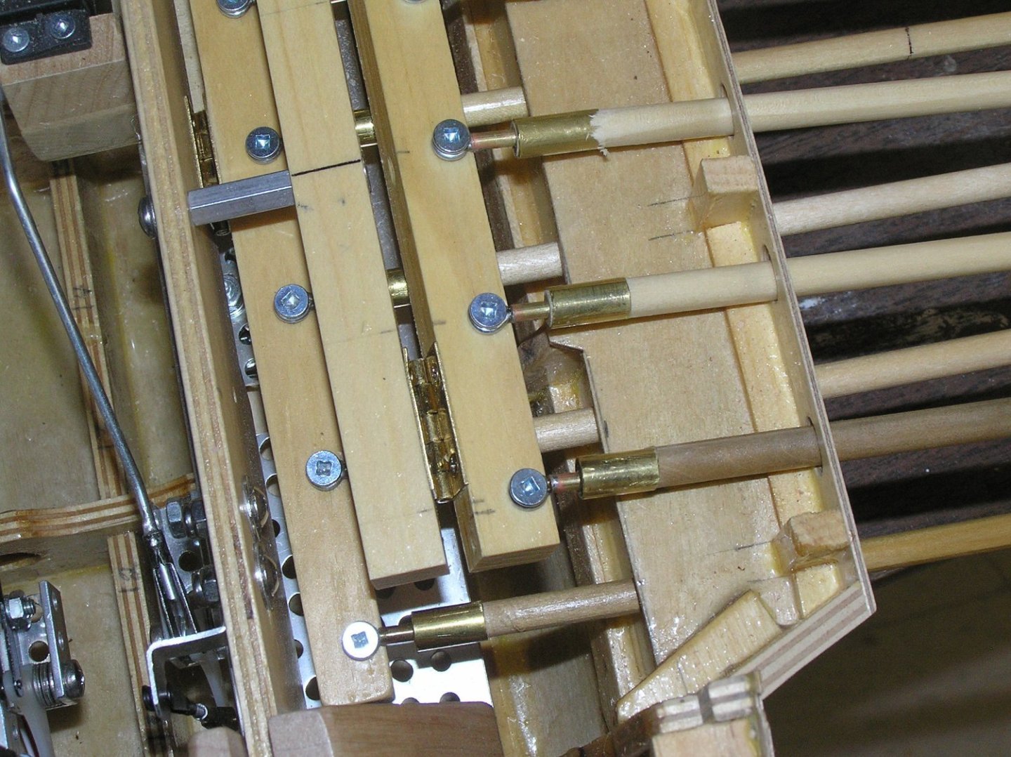
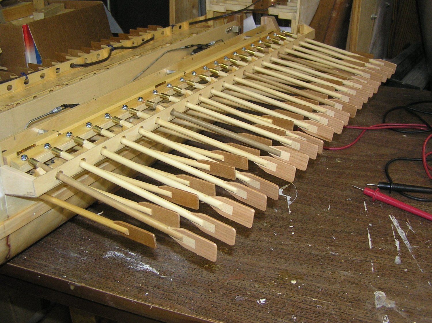
Well I have all 42 upper oars made and varnished, and 21 of them mounted on the port side. It's looking good ..... but .... when I added 1/2" to the upper oar shaft length in order for their blades to lie beyond those of the lower oars, I inadvertently created a problem. The oar ports have to be elongated to allow the shafts to sweep and I mentioned way back there is some play. When I row the oars just on the bench, sometimes a few of the lower blades cross under an adjacent upper shaft at some point in the cycle then there is a clicking noise as they clash and are corrected. The real solution is to redo the loom ends of the upper oars, removing the extra 1/2" so there is some blade overlap which should stop the lower blades from crossing under.
Or perhaps it will be ok when they are all in actual water ..... will do the starboard side then have Sea Trial #3. Soon I hope.
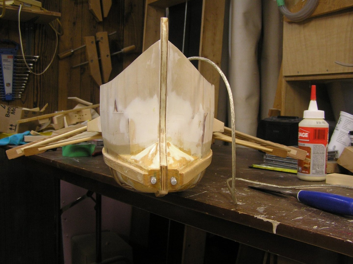
Here are a couple of pics. I changed the mechanism design to use just three hex metal standoffs to support the pivoting beam for the upper oars, as opposed to the solid wood with drilled holes I had before. The holes were intended to provide access to the mounting screws for the lower oars but it was too difficult to get to the screws in, without dropping a lot of them into the bilge, when adding the oars. As can be seen in the 2nd pic the access now is much better. See the increased size of the blades of the upper oars. They look lighter than the lower blades because they're freshly cut cherry; over time they will darken as the older blades have done.

-
Bill, in your second photo above it looks like the t'gallant mast maybe could be struck, or nearly so, if the topmast had normal trestle trees instead of that "cone" shape going all the way around the mast. The cross trees themselves look too far apart to me. Normally the middle one would be pressed against the front of the topmast and the aft one would be pressed against the back of the topmast (as Anderson says too, pg50) which would place them at little more than half the distance apart. And I agree they are too long.
You can't do anything about the first issue, but I would cut them shorter as Marc has already discussed.
Looking forward to working on my SR ......not really 🫤
But I'm taking notes for the future.........🤙
-
Regarding the cross trees, when I first looked through my SR instructions I wondered if it was yet another "Hellerism".
The reason they were constructed as shown by Anderson was so the t'gallant mast could be "struck" ie lowered vertically through the square hole between the first and second crosstrees, just as topmasts are dropped through the lower mast tops. Heller's construction leaves no such cavity.
-
2 minutes ago, Hubac's Historian said:
Don’t quote me on this, but in actual practice everything is derived, proportionally, from the lower main mast.
...... which is itself derived from the ship's beam (Anderson, Chapter 1 part III, pg 15).
Sorry to "quote" you, Marc. 😉


Barque Stefano by robdurant - MarisStella - 1:63
in - Kit build logs for subjects built from 1851 - 1900
Posted
Yes, I paid a fortune to case my Heller Victory, but after five years of working on it it's an investment in keeping it safe and free of dust.