


Ian_Grant
-
Posts
2,028 -
Joined
-
Last visited
Content Type
Profiles
Forums
Gallery
Events
Posts posted by Ian_Grant
-
-
Bob, it would be worth a little debugging before spending money on a new RC set!
The two most likely problems that come to my mind are (1) the ESC somehow burned out, and (2) the RC Tx and Rx are no longer binded for some reason. I'd be surprised if anything is wrong with the Tx or Rx.
If the ESC is burned out then it will not supply power to the receiver via the 3-pin "throttle" connection and the boat's innards will be inert. I recall you have a voltmeter at least; with the battery connected to the ESC measure the nominal 5V it should be supplying for the Rcvr. Centre pin is +5V, GND is usually a black wire. If no voltage, it's the ESC.
If the Tx and Rx are no longer linked, then the Rx will ignore the Tx and again the boat will be inert. You could test this by connecting any 6V battery to the Rx's "BATT" pins (if you have a spare 3-pin connector with the wires, or cut one). Now that the Rx does not depend on the ESC, test for servo operation. If nothing happens try repeating the binding process. If you're sure they are binding according to the instructions in the TX and Rx manuals, then OK maybe one of them is at fault but again I'd be surprised.
Wish I could just pop over to help.....
Good luck!
- thibaultron and bcochran
-
 2
2
-
Excellent display! And I'm awed at the speed with which you produced this......😮
- mtaylor and Glen McGuire
-
2
-
-
Progress slowed down due to some paying jobs done for neighbours, and I finally got around to opening our pool today.
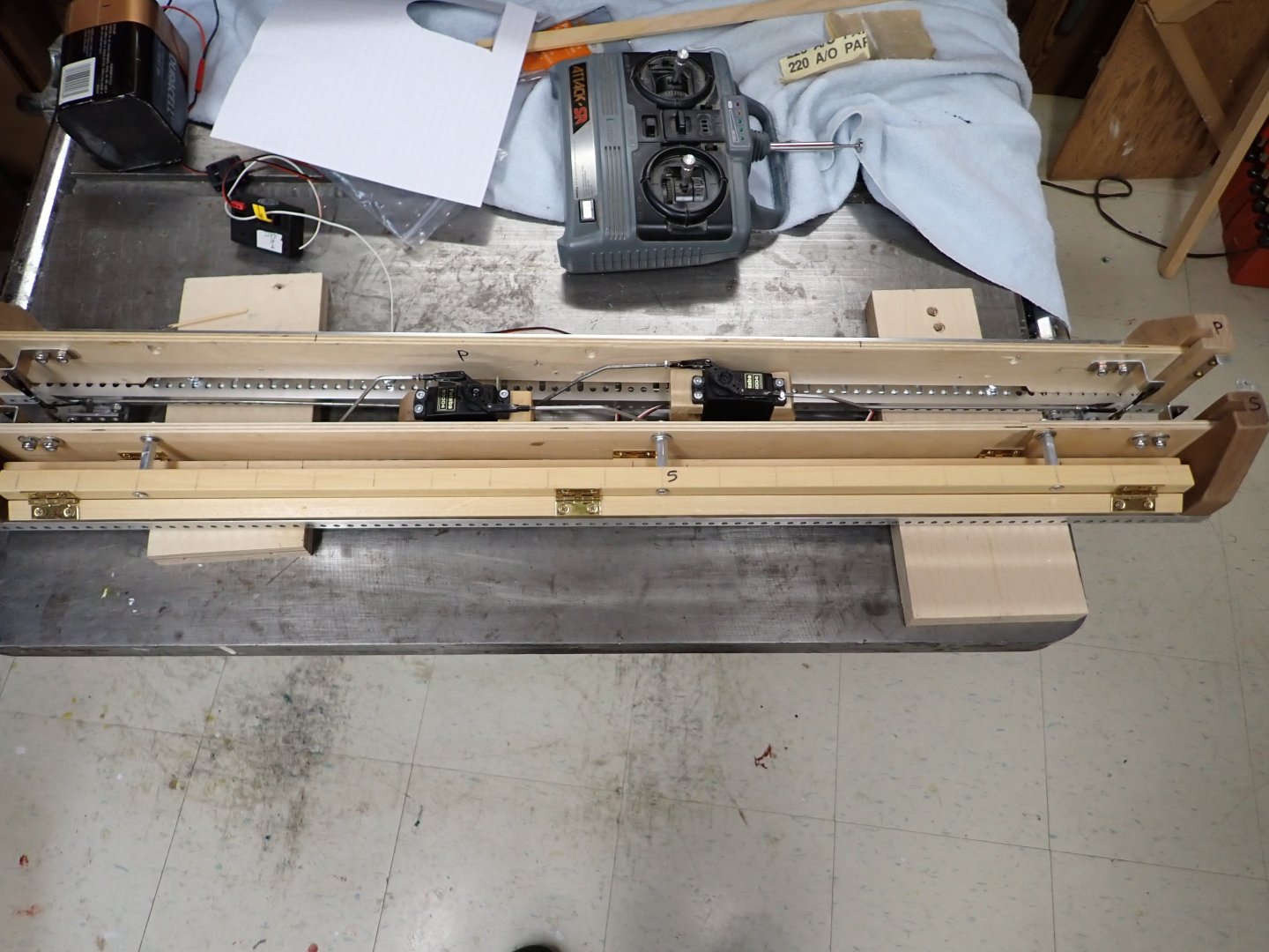
Port and starboard mechanisms reassembled; lift servos moved closer to amidships so they won't collide with the fore and aft companionway ladders. Also changed the upper oar bar mounting holes to vertical slots to permit adjustment of the upper oars relative to the lower sets.
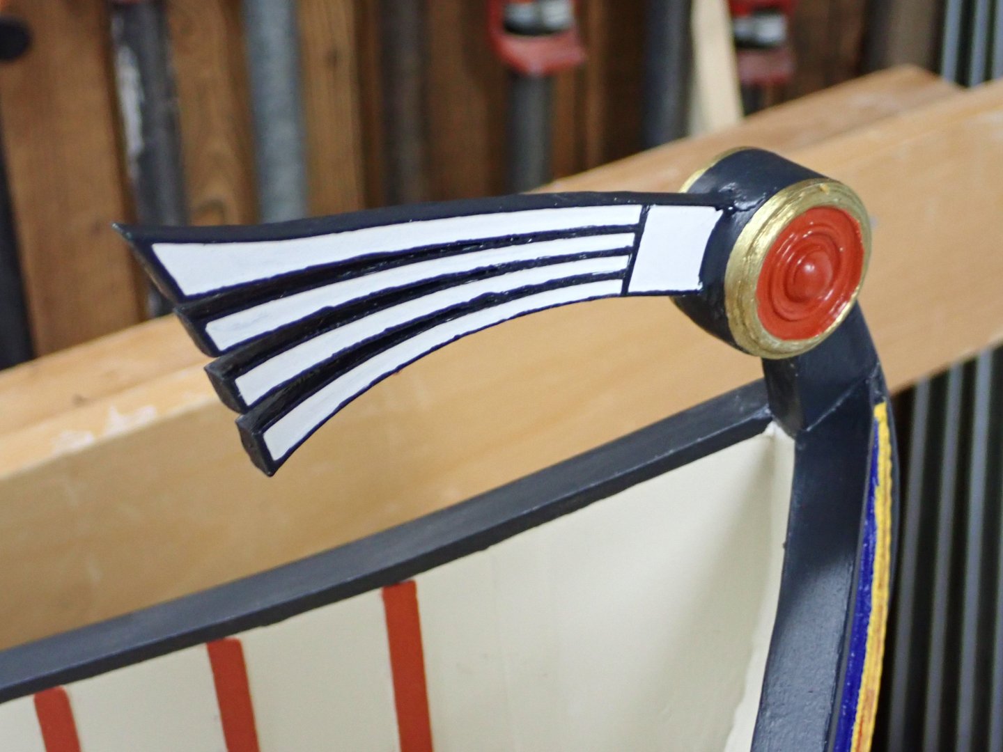
Completed detail painting of the fantail decoration.
And I received my NiMH battery pack (5 cell, 6V, 3800mAh; far smaller than lantern batteries), and a slow charger (600mA) so charges will take overnight but that's ok with me. It's less stress on the cells.
With the pool now open I can try the boat again. I want to drop the waterline a smidgen, to mid-wale which was the original plan. This will give the oars a little more clearance from catching crabs. I fear I may have to drill out some of the fixed lead ballast in the bow......fingers crossed the drill doesn't "catch" and go through the bottom. 🫢 I have yet to make the oar modifications too. Also started to think about how to make the commander's "cubby" at the stern a convincing "canvas" shelter.
This has dragged on too long; need to finish it for summer.
-
She's a beauty..........
- bcochran and thibaultron
-
2
-
Fully agree. It was all working, it's going to be something silly. After all your time and effort it's worth ten minutes in a hobby shop for diagnosis.
- thibaultron and bcochran
-
2
-
Is the ESC one of the type where one must power on with throttle at "stop", then move stick/wheel to full ahead then full reverse?
-
If the screws' blades are twisted in opposite directions, then they need to turn in opposite directions to propel the boat in the same direction ie forward or backward. Yes, just reverse the wires on one motor. Note - you may find on the water that when you push the throttle stick in what you conceive to be "forward" the boat goes backward. Unless your transmitter has servo-reversing you'll then need to reverse the wires on both motors.
-
-
4 hours ago, GeorgeKapas said:
Thank you Ian! Oh well, my unorthodox builds are still a bit of a way to go to become masterpieces hahaha 😅
Respectfully disagree, considering your outstanding Mahmudiye and Venetian galley builds.......
- Keith Black, mtaylor and GeorgeKapas
-
3
-
Good to see you back, Bob.
Yes, NiMH cells in theory are 1.2V so your 6-packs should give you 7.2V.
However, they do charge up to a slightly higher voltage. When taken off the charger they're usually around 1.4V, or 8.4V for your six-packs, as you observed. Does it matter? It doesn't matter for the batteries; this is normal behaviour. They should drop slightly after a few hours off the charger. What about your ESC and motors? It probably doesn't matter (I think you have brushed motors?) although they will burn a little more power since more current flows with the higher voltage. I think you got your stuff from "Big Bob"? - if so he will have chosen compatible components, knowing the characteristics of NiMH.
In use the pack voltage should drop to 7.2V fairly quickly.
Looking forward to the maiden video from the pond! She's a beauty.
Regards,
Ian
- bcochran and Ryland Craze
-
2
-
Gee, I was looking forward to the masting and rigging on this magnificent model.......
- FriedClams, Siggi52, Keith Black and 1 other
-
4
-
Another masterpiece in progress!
- GeorgeKapas and mtaylor
-
2
-
She was a lovely ship as were all the steel windjammers. I was working on a Heller plastic "Preussen" 5-master until I interrupted it to try my first RC build in 40 years but I hope to finish "Preussen" this winter.
Then I want to make an RC square rigger. Reading about Neville Wade's many sailing models (including one based on Herzogin Cecilie) makes me want to build a 4-master. However, I was thinking of ordering Underhill's drawings of L'Avenir instead since she was a slightly smaller ship and so would be slightly larger scale.
Looking forward to seeing your HC restored to her full glory!
- mtaylor, Keith Black and Mirabell61
-
3
-
12 hours ago, thibaultron said:
Fine Scale Modeler just published a Figure Painting special Issue. It has been about a month, but it may still be available.
Yes, I saw that in Chapters. Incredible painting job on a small bust of Napoleon even including his five o'clock shadow.
Model painting has come a long way since I made plastic airplanes as a kid; as far as I can see the typical model now has about 15 spray coats of paint for various purposes.
- thibaultron, mtaylor, Desertanimal and 2 others
-
5
-
Missed this build originally but now I'm on it. Wonderful!
- Glen McGuire and mtaylor
-
2
-
You're planning full sails? Wow!
- Glen McGuire and mtaylor
-
2
-
Really looking forward to this!
- Glen McGuire, PvG Aussie and mtaylor
-
2
-
 1
1
-
2 hours ago, Hubac's Historian said:
Hi Ian - I think the lower wale is also above water in post #103, but it is an abbreviated quarter view.
Thanks Marc; looking back I see it is the Monarche whose wale is underwater amidships, not the DR.
-
I'm late to this party but wanted to add my congratulations on the very nice final model! She looks great in her display case!
I admire your determination to overcome this old model's issues and look forward to your next build.
Ian
- Old Collingwood and Canute
-
2
-
You'll have to try harder - I had mine for 34 years before starting her. 😊 It's a common story among Heller Victory builders.
Good luck with the kit, and are you aware:
- of all the kit shortcomings?
- of the best book to guide you through the rigging?
- that brass etch parts are now available to enhance the build?
If not, all this and more can be found in Heller Victory build logs, here.
Looking forward to your build log!
Ian
- mtaylor, Baker and Keith Black
-
3
-
I can never in my ignorance pick out in the photos what you are discussing in text, nonetheless I am enthralled by the complexity of this build. Would love to see it first hand in water. Congratulations and keep up the amazing work!
- Glen McGuire, Thukydides, Canute and 2 others
-
5
-
A good while since I posted. We were away a couple of weeks hiking in various canyon national parks at the corner where Utah/Nevada/Arizona all meet. Great trip which we hugely enjoyed given terrain which was like nothing we'd ever seen.
Here are a couple of shots taken at Bryce Canyon. There are various trails which go down and wander among the hoodoos, each of which ends with a climb back up to the rim! One day there was snow, 0 deg C, so the family opted out but I had a great hike; muddy at first but tee-shirt warm at the bottom.


And here is a fun photo taken at the trading post near Bryce Canyon. We will hang it next to a similar western-themed sepia shot taken when the kids were four and eight.

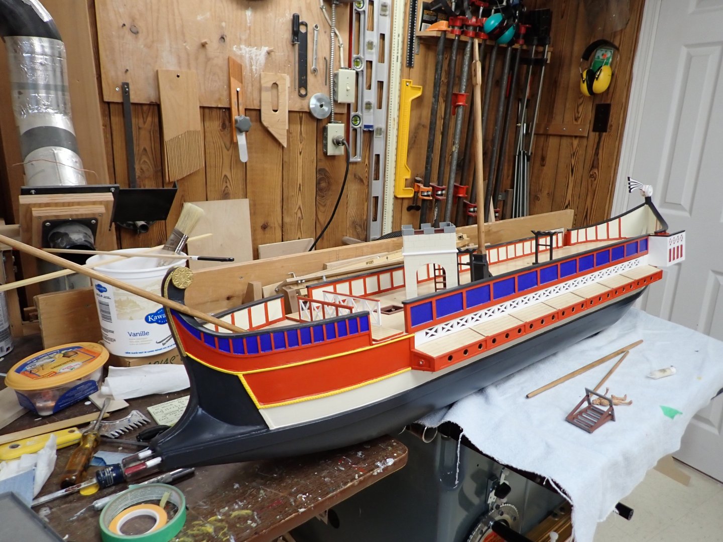
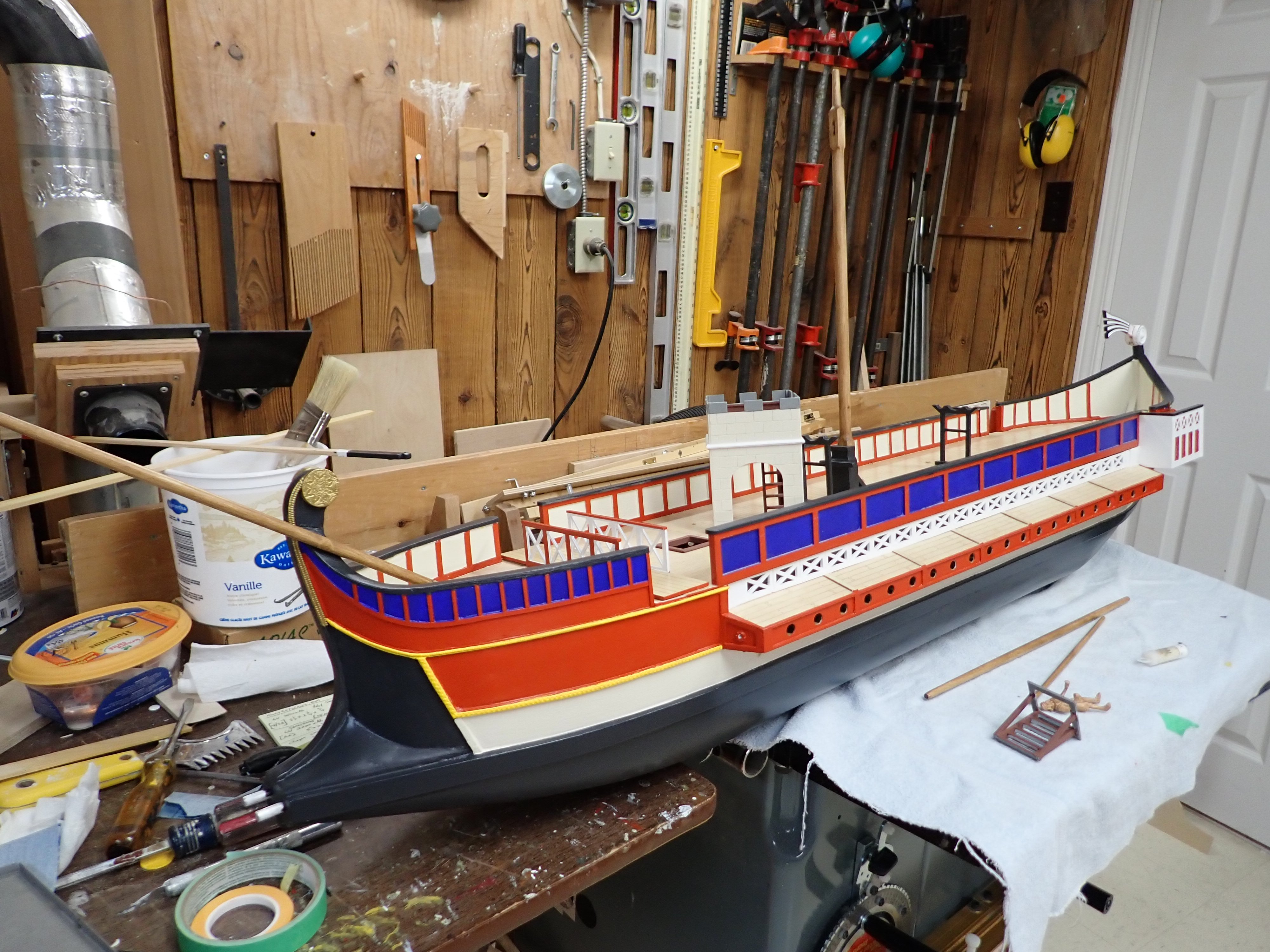
Now back to the ship. I finally painted the bottom and the main wales black, actually "Dark Secret" from Home Depot which I would liken to Humbrol "Tank Grey". It was a relief to finally see the seams between the various small pieces of plywood skin disappear. The oars and mechanisms have been removed to allow mods. I want to make the lower oar blades the same increased size as those of the upper oars; shorten the upper oars by 1/2 inch; elongate the mounting holes of the upper oar beams to allow adjustment relative to the lower oars.
I had a brief panic about NiMH batteries. Way back at the start of this project, I looked around and saw NiMH 5-cell "packs" at 6V and thought, ok, we're good to go with 6V analog servos. But recently I read that a 5-cell NiMH pack charges to something over 7V but soon drops to 6V when loaded. Consulting with the Hitec technical support line yielded the info that it's OK; the analog servos will be fine.
Now I've been looking for a suitable battery pack and charger. I put my ammeter at the battery when rowing in water and was surprised to see it only draws about 3/4A whereas I'd been expecting maybe 2 or 3 amps. I have my eye on a pack and charger but haven't ordered yet.
I also have the bigger resin-printed ballistas from my brother. He is now tasked with printing the rudders for this thing in transparent resin, which I really need quite soon in order to progress further.
- gjdale, Keith Black, Siggi52 and 7 others
-
10
-
Wow, those planks are going to look awesome when sanded...........👍
- KeithAug, Keith Black, mtaylor and 1 other
-
4


Roman Quadrireme Galley by Ian_Grant - 1/32 Scale - RADIO
in - Subjects built Up to and including 1500 AD
Posted · Edited by Ian_Grant
Thanks Steven! Yours looks great but it's far beyond my artistic ability.
Not sure how I want it to look. Or what they had if anything. In Pitassi's book some of the larger ships have what looks like a permanent structure, like the quinquireme in this video ( see time 0:46). I think a quadrireme would require something lighter due to reduced size and number of oarsmen. Pitassi indeed shows nothing in the quadrireme drawing but has an arched tent-like item in other drawings.
Something more like what is shown in the ships here. Most have a "tent" of some sort with, thankfully, one plain colour or at the most stripes. That's a relief.
https://naval-encyclopedia.com/antique-ships/roman-ships
A snag is that I was planning to attach the cubby to the rear hatch to serve as a handle (similar to the boarding bridge and the forward hatch) so it can't actually be soft. Maybe a "soft-top" arch with hidden wood in the lower sides for my big clumsy hands to grip?