Ian_Grant
-
Posts
2,156 -
Joined
-
Last visited
Content Type
Profiles
Forums
Gallery
Events
Everything posted by Ian_Grant
-
 Just so long as they aren't going to nail you with "brokerage fees" or whatever. 😬
 -
Dave, your model is very very nice! Sorry to be so late to your log. By the way, my mom and dad retired to Cobourg, away from Bramalea thank God, and what a pretty little town to be in! We all loved the beach and the ice cream place beside it. I used to cycle a loop up to Rice Lake and back when visiting; the descent back to Cobourg was always exhilarating!
- 43 replies
-
- 2
-

-
- Mayflower
- Model Shipways
- (and 1 more)
-
Your kit must be from a different lot, Bill. Mine was still molded in funky black, red, and blue plastic. Your muted tones might be easier to paint!
- 1,508 replies
-
- 3
-
-
- Le Soleil Royal
- Heller
- (and 1 more)
-
I always enjoy a Victory build, and there aren't so many at this scale. Are you aware of Noel Hackney's little book on Victory, in the "Classic Ships and how to model them" series? His book is written for builders of your airfix 1/180 model and provides many many "upgrade" suggestions as well as complete rigging instructions. Well worth the price. Meanwhile, I look forward to following you.
-
Well, Nelson did chase Villeneuve across the Atlantic and back a little while before Trafalgar (Victory's only trans-Atlantic voyage, memorably painted by Geoff Hunt); maybe he bought some Bourbon in the Caribbean somewhere....😄
-
They're great Bill! I love the cargo being swayed aboard - rum barrels? Lime juice? Two thumbs up from me 👍👍
-
Yes, Ottawa is beautiful. Thank God I was hired here straight out of the University of Toronto and so was able to kiss goodbye to traffic-choked "T.O." forever. Wonder which parts you saw on the show? Rockcliffe Park perhaps? (A wealthy enclave). (I don't live there). 😃Although I did once work on a job adding walk-in closets in the basement of a tech-megamillionaire's house in there (he flies a WW II Spitfire, amongst others in his collection!). Have you visited here at all Bill? If you like the outdoors it's a great place to live. Bicycle paths along the rivers and the canal, as well as through various neighbourhoods; great swimming in lakes 1/2 hour across the river, fantastic x-country skiing just across the Ottawa River in Gatineau Park (about 200km of well-groomed trails which can be hiked in the summer); several local ski hills plus Mont Tremblant 3 hours away; a plethora of skating rinks (I can think of eight surfaces within 10 minutes of my house) plus, even better, outdoor skating on the frozen canal (8 km one way) in the winter, also groomed, weather permitting. And this town is just not that big so it's easy to get out into the country. Maybe I could get a gig with Ottawa Tourism? 😄
-
But doesn't nail polish reek like model airplane dope?
-
She looks Great Bill....but not quite so fast....😁....the bower anchor shank should be above the middle gun deck ports - see the pic of actual ship in #1419. You may find it difficult to hang the anchor in the shoe while having it this high, I know I did because the tip of the fluke caroms off the hull before its fat end sits in the shoe. Something wrong there! I think I trimmed a little off the fluke's tip to get it to hang. Once you lift the bowers up a little, you truly are done....😃👍🤙 Looking forward to following your SR build! It's been great fun. Regards, Ian
-
Yup, we encountered no less than seven cement trucks coming from Hana, usually on a hairpin bend. I was starting to wonder if there was a cement truck factory there. 😄
- 134 replies
-
- 3
-

-
- Captain Kidd
- bottle
- (and 3 more)
-
Highly original, as always! 👍🤙 That second symbol we ran into in Hawaii, when people were giving me it when the Hana highway on Maui dropped to a single lane at one of the many narrow bridges and I yielded. 👀 I asked one of our rental owners if they were in effect giving me the finger but apparently it means, loosely, "Stay cool". Interestingly one of the characters flashed it on CSI:Hawaii last night.
- 134 replies
-
- 3
-

-
-
- Captain Kidd
- bottle
- (and 3 more)
-
You've got it. Even if you add the buoys you don't necessarily have to add the coils. At sea the buoys would not be rigged, just hanging on the shrouds out of the way. I just connected one to show what it was. Rather like the way they hang each anchor on the real ship differently, to show the different stages of catting and fishing.
-
**** This post is mainly a note to myself as an aide-memoire in the event that I lose the napkins I did these calculations on **** So the set of three drawer slides under the aluminum channel weighs 0.38 kg. Eliminating them on two sides saves 0.76kg. Almost exactly half the weight in excess of that of the "Lion". I estimate I get 1kg (2.2lb) additional displacement for each 1/4" increase in the galley hull's depth. That's without making the bilges fuller. To add the 4.64kg of additional displacement required, keel depth (if keeping the slides) must increase by 1.2". That seems a lot. I can gain an additional 0.7kg by making the bottom flatter and the bilge fuller. Remember that Lion is all 1/32 ply skin and no fiberglass (since all ply panel joints fall on ribs or stringers). If I plank the galley which means F/G exterior it could be heavier. God, what a guessing game🤣😢 **** End of Note ****
- 536 replies
-
- 2
-
-
- Quadrireme
- radio
- (and 1 more)
-
Well, 4-1/2 feet, 5 feet; near as dammit after 40 years out of your sight! 😀
- 536 replies
-
- 2
-
-
- Quadrireme
- radio
- (and 1 more)
-
Hi Bill, that's the line to the anchor buoy hanging on the shrouds; it goes up and is coiled beside the buoy. It only looks like it goes to the block because the threads run very close together. The three blocks are the same rig as the three in your photo, except you have rigged your upper block in black. These are on the fore topmast breast backstay. The chain is the shank painter which I described in #1419.
-
The oars take up about 30" of the proposed 54" hull; that's the size of the "Lion".
- 536 replies
-
- 1
-
-
- Quadrireme
- radio
- (and 1 more)
-
Richard, is the plan still to install an oar drive mechanism? If so I look forward to it eagerly.
-
While driving to the cottage today I wondered about eliminating the heavy metal drawer slides since I only need 3/4" of movement each side of centre position. What if I retained the aluminum base beam and just had it slide on Lee Valley UHMW "Slippery Tape", intended to lubricate drawers in carcasses? It would just need a couple of short guide blocks to retain it laterally, with a bit of a lip to retain it vertically. Guide blocks could have the slippery tape too. There would be nothing to get rusty..... Will weigh the slides intended for the other side in the morning. Now all I need to do is change the beam to baltic birch ply and all the servocity stuff (which I paid a fortune for) will be "made redundant". But I like the idea of the aluminum base channel sliding on the tape, which only its two flanges would contact as opposed to the full face of a plywood base. Also the ply base's edges would be hard to totally smooth out.
- 536 replies
-
- 2
-
-
- Quadrireme
- radio
- (and 1 more)
-
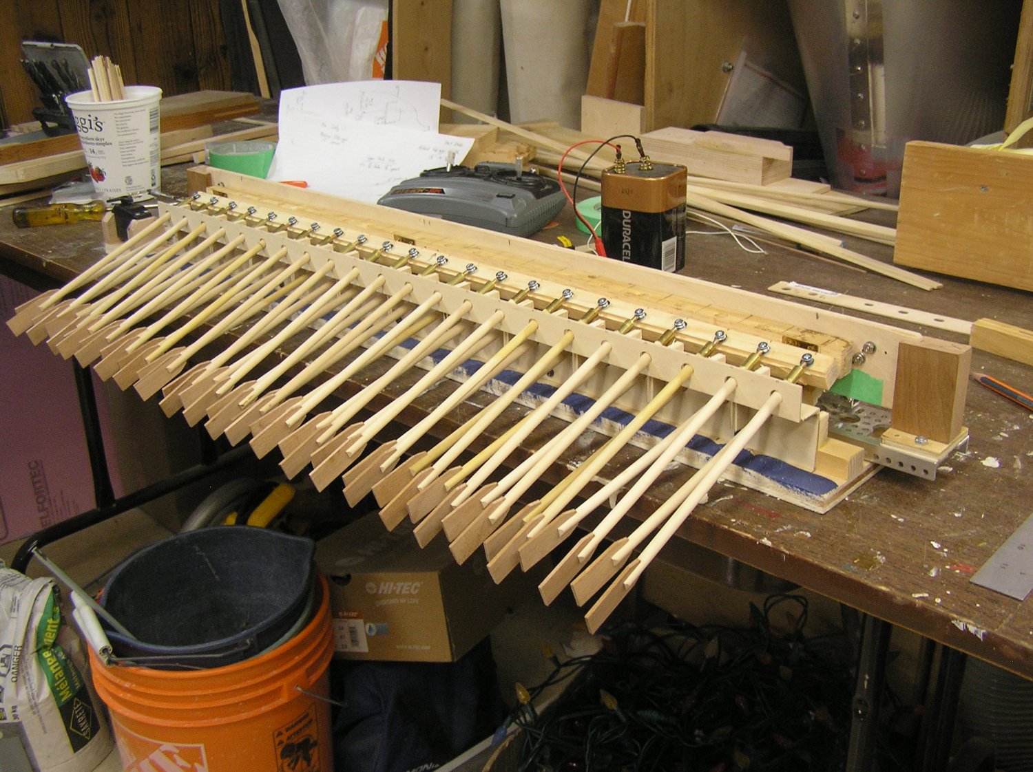
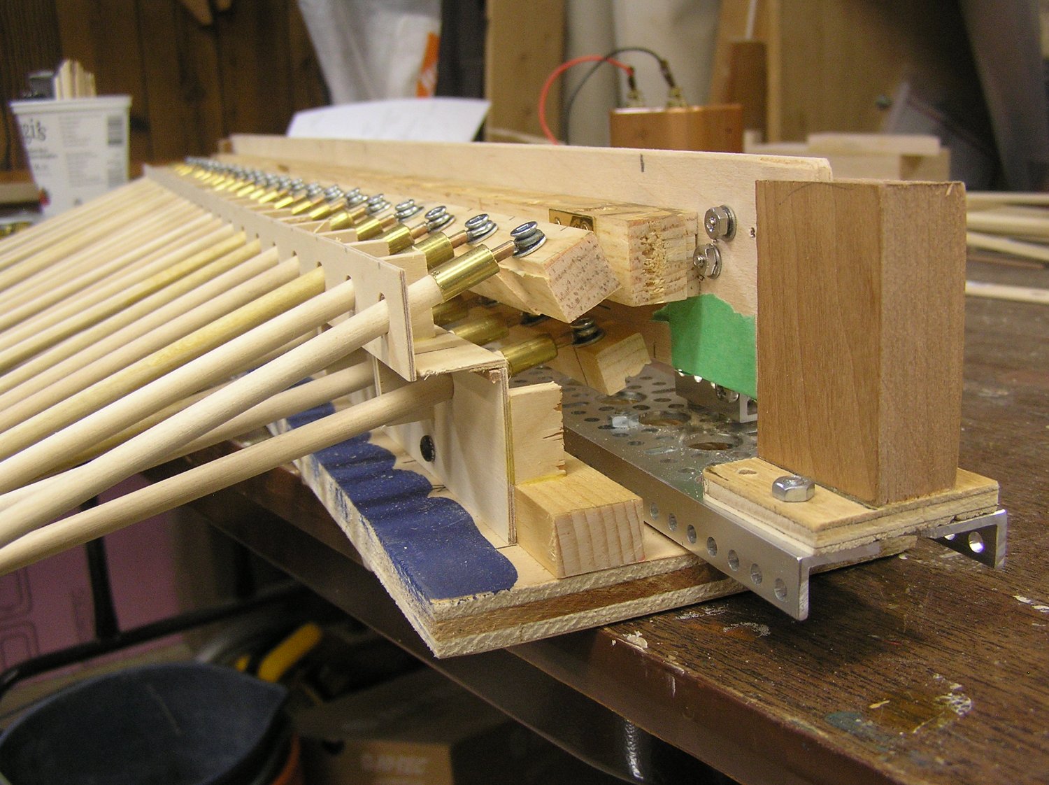
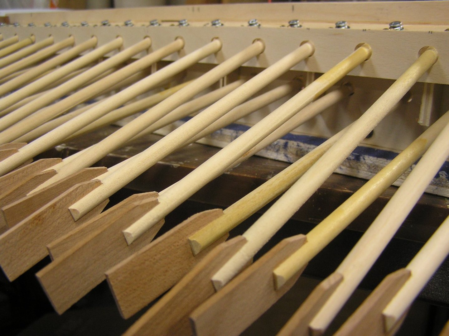
I hooked up the Arduino to see the entire reme rowing. There was bit of a rattle when moving up and down at the ends of the stroke which I attributed to the loom eyes shifting along the flat head screws mounting them to the oar strip (the screws had to be left loose to allow the oars to pivot up and down since the oar strip's upper surface remained horizontal as the beam moved). The oar strips were changed to the hinged design, allowing the loom screws to be tightened as theoretically the looms only need to swivel on the strip, not tilt up and down. Here are some pics of all 44 oars in both remes installed with the new strips. In the second one you can see the strips tilted, with one of the hinges quite visible. I like the third one which hints at how the galley hull will look with the oars emerging; of course the actual hull will have much nicer brackets supporting the outrigger. I'm happy that the angles all seem to match my revised drawing of oar geometry. What I need to do now is determine the range limits of the servos, in terms of their control pulse widths in microseconds. For this I need a little test program, and for that I need an Arduino book again because I need to use a function I have never tried. Again, I find the on-line Arduino help not very helpful at all; I much prefer to have a physical book I can leaf through. Back to the library........... Once I know the servo ranges I can modify the code and see the whole shebang row 🤪. On another topic I borrowed a cat weigh scale from my wife's vet clinic in an effort to determine what kind of volume the galley's lower hull will need. My old battlecruiser "Lion" mentioned earlier in this log is about the same length and beam as proposed for the galley. It weighs 4.16kg empty (ie no motors, battery, or fixed ballast), 6.85kg ballasted to waterline. My calculated estimate of her underwater displacement, by dividing the hull into rectangles and triangles on paper, was very close to this. Let's assume the empty galley hull being of similar wood construction weighs about the same as the Lion, say 4.2kg. The oar mechanism with oars and servos weighs 1.87kg, two thus weigh 3.74kg. Galley hull plus oar drive weighs about 8kg. Add about 0.34kg for the NiMh battery and we're at 8.34kg, which is 1.5kg heavier (!!) than the Lion. I estimated the displacement of the galley underwater hull by similarly dividing it into rectangles, triangles etc, and came up with about 3.7kg which is 4.64kg too low. Bedford was right, again, back when he suggested I make the bilge fuller to gain volume. I'll need to probably abandon all pretense of a "correct" underwater hull in order to get the volume I need. Must double-check my galley volume calculation first, since it's quite low. My plan now is to come up with a keel depth and beefy midships section shape to get me the required volume, then carve two half hull representations of the transition from this cross section to pleasing bow and stern. Then I can use a contour gauge to get intervening sections to cut bulkheads. Best way I can think of rather than fiddling with drawings and templates. Or spending months mastering CAD.


- 536 replies
-
- 5
-
-
- Quadrireme
- radio
- (and 1 more)
-
Bill I would think long and hard about trying to change them at this point; in the end it makes little difference. Yes, Robert's rigging looks very neat. He is helped by the Caldercraft's larger scale...😄
-
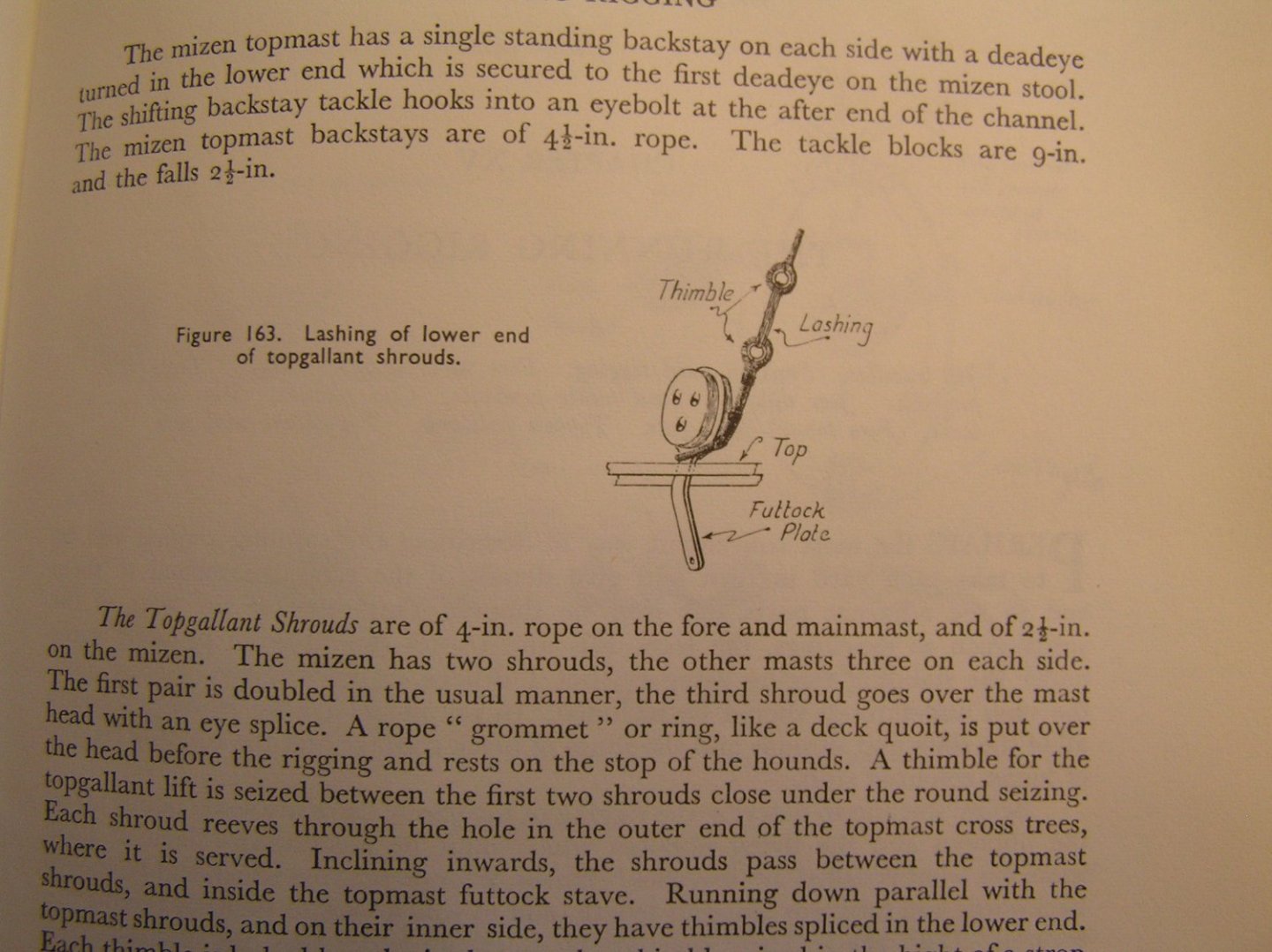
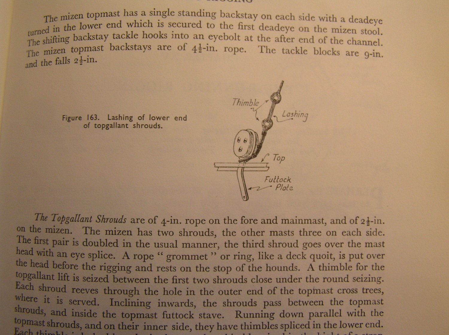
Robert and Bill - my bad! Somehow I just got it in my head that Robert was talking about the shrouds. Yours are nicely done! Hmmm..... Petersson shows the topgallant lifts indeed belaying to cleats on the topmast shrouds. Lees says the topgallant lift was "taken to the lower top where it was made fast to a deadeye or cleat". I know I did not add cleats for these lines, I must have just tied around the strop, for what it's worth.
-
Bill, shroud cleats are only used for some running rigging, at deck level. Actually Robert has the belaying point for the topgallant shrouds correct, except that there should be thimbles. Somewhere earlier in this log I posted a pic of mine. Here is the relevant Figure from Longridge. Robert, if you don't have his book I respectfully suggest that you look for a copy; it is the bible for rigging this ship. Realistically, however, you could omit the thimbles; they're hard to see behind the topmast shroud lashings anyway.