Ian_Grant
-
Posts
2,156 -
Joined
-
Last visited
Content Type
Profiles
Forums
Gallery
Events
Everything posted by Ian_Grant
-
 You're probably right; the aluminum is riddled with holes actually. And will never warp. Possibly my best plan is to design the hull to give me the estimated displacement, then if the built hull turns out to be a bit heavier, eliminate the drawer slides thereby saving the 0.76 kg. If it's lighter, I could add internal ballast. Or eliminate the slides anyway and have more ballast. I will probably be quiet for some time now. Need to review the library's materials on using their machines then get myself approved for them. Will post when there is something to show. Don't anyone hold their breath.....😵
- 536 replies
-
- 3
-

-
- Quadrireme
- radio
- (and 1 more)
-
I guess we'll find out! Yes, a crew will be needed. I'd like to have the two helmsmen, some marines, an optio commanding them, a couple of archers in the tower, crews on the scorpios (artillery), commander gazing forward,..... I've been talking to my brother, the 3D printer guy, about that. For example, I found this guy on the internet; he's "fully rigged" which Andrew says means you can pose him as you like before printing; as opposed to printing then having to cut him up to move his arms etc. You could even scale him to get men of different heights. For $40 you get the file then print as many as you like. He'd do for the marines and could be modded for the optio. I think I will be learning about resin molding in the future. https://www.turbosquid.com/3d-models/maya-roman-legionnaire/371829 Glen, that's hilarious! 🤣 But actually you have the little guy on the stern....😄
- 536 replies
-
- 1
-
-
- Quadrireme
- radio
- (and 1 more)
-
Bill, they used to paint the u/w hulls with "white stuff", their version of anti-fouling paint. It was a white sulfurous resin. I plan to sand off all the exaggerated wood grain below w/l when I get to SR and just leave the plank seams, for what it's worth. Oh and by the way, you should move the w/l up the hull which means sanding off Heller's molded w/l guidance. I have no experience with silver solder but it seems to give far stronger joins than lead/tin. I think there is a whole thread on soldering on this site.
- 1,508 replies
-
- 2
-
-
- Le Soleil Royal
- Heller
- (and 1 more)
-
First the ship, then the second bank of oars. I'm finished with the software for now so I'm going to dismantle the oar bank to weigh the aluminum channel; if it's fairly heavy compared to plywood I will modify the bank to a wood plate sliding on Lee Valley "Slippery tape" and try that out. If successful I will go with that approach. As I mentioned earlier I need to beef up the u/w hull to displace the resulting expected weight of it all. What I am coming up with to attain the necessary volume is a most inelegant midships shape 😬. When I have a hull I will be measuring its displacement ASAP to verify. I'm even thinking about just covering the hull framing in two layers of plastic wrap or silkspan or something, just to try to make a quick measurement of weight required to get it to waterline. Here is video of another model; 1.3m and 6.5kg displacement. Not sure if he has a propeller "assist" in her. My estimated hull is a couple of inches longer and 1.8 kg heavier, half of which is the darn drawer slides.
- 536 replies
-
- 3
-
-

-
- Quadrireme
- radio
- (and 1 more)
-
Modified code again to replace the rectangular stroke with parabolic entry and exit on the power stroke with flat central portion. Now that I've seen rectangular, trapezoidal, and parabolic strokes I conclude that the stroke shape is not important; the vertical movement is so much less than the sweep movement that the eye cannot discern the difference. Since I now had the parabola formulas in the program I decided to have some fun with the stroke as shown in this video. I'm very happy with my code; it has been robust in the face of frequent changes and obviously is not a wobbly house of cards which is what I was afraid I would end up with. Perhaps "C" itself forces you to write in a structured way..... I will now move on to a hull design and build (finally, I hear people saying......). One last thing to show - I built a water tank to see the oars row in water. Not for long as they are glued with yellow carpenter's glue and are not varnished or painted as yet. I'll need to sand the corners off the blades before applying finish. Anyway here is a brief video. You can see where my garbage bag liner sprung a leak 😆. No danger of the mechanism flying off to the side..😄..I must say it's hard to imagine this having the power to move what will be a fairly heavy hull. I hope to God after all this effort, and effort to come, that it does.🤞✌️
- 536 replies
-
- 5
-
-
-
- Quadrireme
- radio
- (and 1 more)
-
It does look great! Glen, what size is that chest - what's the grid on your cutting sheet?
- 134 replies
-
- 3
-

-
-
- Captain Kidd
- bottle
- (and 3 more)
-
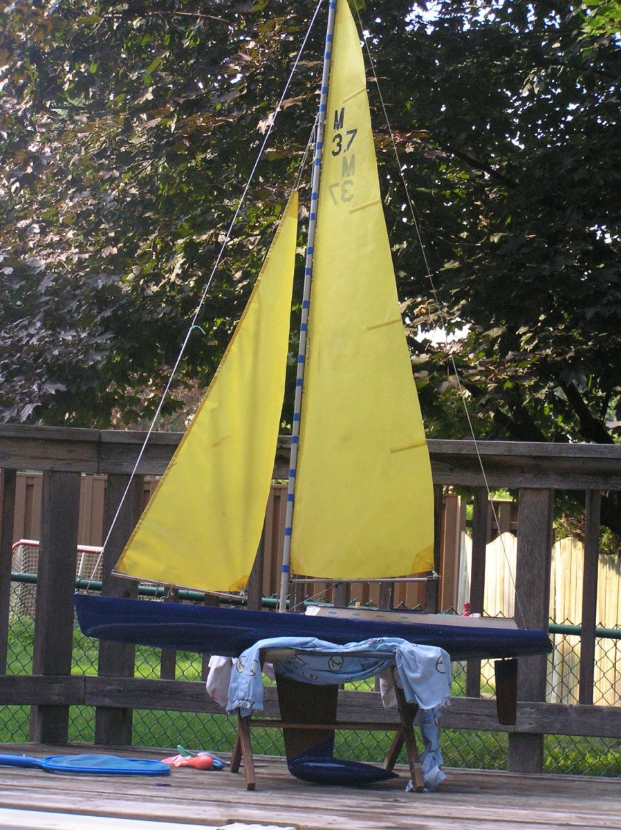
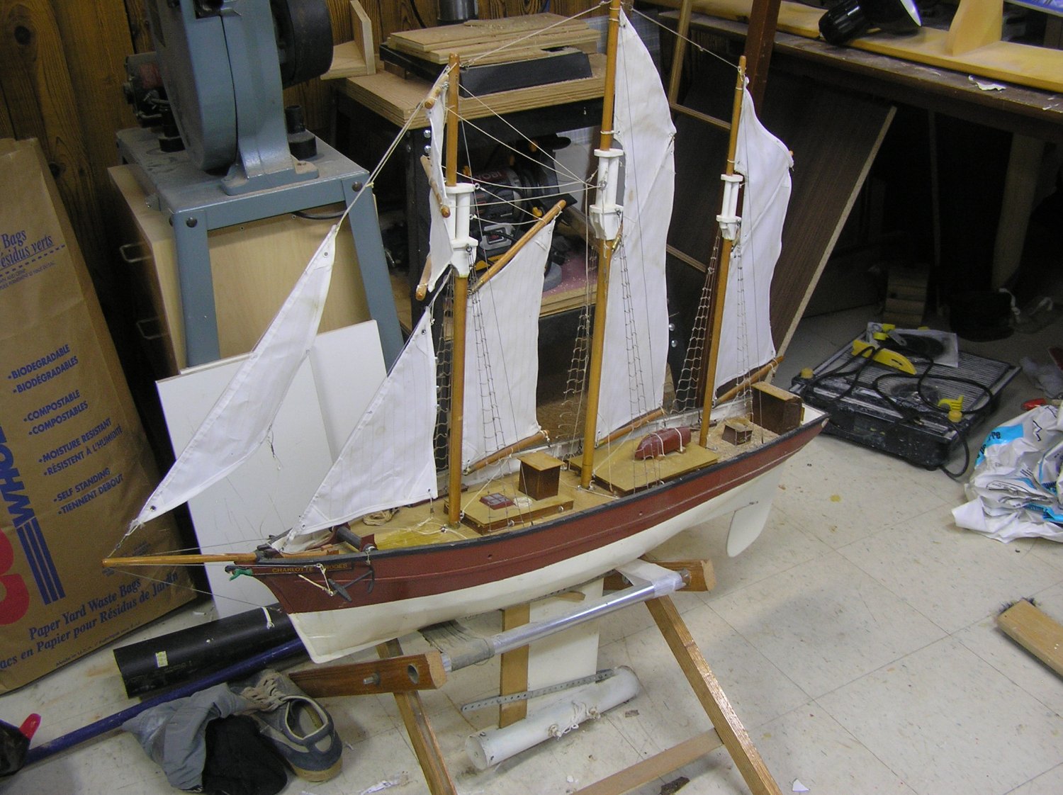
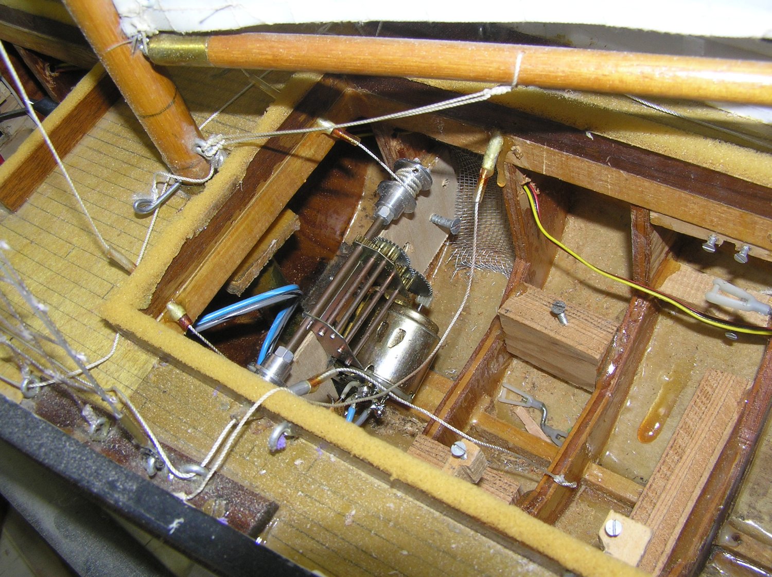
Maxx, I too would like to build an RC square rigger, after I get an RC galley going. I did an RC topsail schooner as a teenager back in the late 70's when the average sail winch was about the size of three hockey pucks😄. She sailed but I had trouble tacking her; mostly failed to get past the wind's eye. I decided my fin was placed a little too far aft but then I moved out and life "intervened" as they say. Here are some pics of my RC sailing models as they are today. The yacht was refitted a few years ago. That's a drive from a plastic model tank which was used to adjust the square topsails on the schooner. So I'm quite interested in your model. That is some honkin' motor!! Is it just back-up for when the wind dies down? Are you going to have full control of all the square sails? I'm curious about your winches; did you order winch or drum type? I'm guessing drum since you have no bulkhead cutouts to give an arm room to swing. My old winch was a big drum which was troublesome if hauling in a slack sheet since tangles could ensue. There is a great book by Phillip Vaughn Williams, "An Introduction to Scale Sailing Models" which outlines different ways of rigging winches. Excellent read! Looking forward to more of your build.


-
....if you say so.....😄
-
And he used to be MichaelD. Perhaps he is dodging the tax man? 😄
- 1,508 replies
-
- 4
-
-

-
- Le Soleil Royal
- Heller
- (and 1 more)
-
Oh yes I'm sure they would!
-
Hello Jack; I live in the west end near Pinecrest Cemetery, so, nearby to you. Yes Great Hobbies at Hunt Club and Merivale has wooden ship kits, mainly Occre, and even a few fittings. They're about it for wooden kits in this town. They're mainly into RC cars and electric airplanes by the look of it. I can never seem to spend less than half an hour there even if I just dropped by for a small item. OOPS! Later Edit.....They do carry Amati, Billings, Corel as well as Occre for on-line ordering; that's why i remember only seeing all those white Occre boxes. They do have those cool OCcre metal locomotive kits which I was tempted by last time. 😲 Welcome to MSW and I look forward to seeing a ship build occurring right here in Ottawa! There aren't too many of us I think. 😄
-
Mayflower by tj456 - 1/19 scale
Ian_Grant replied to tj456's topic in - Build logs for subjects built 1501 - 1750
I've been wondering about that too..... -
Looks great! I took a look at those after-market parts links you mentioned, wow are they ever nice for upgrades. I particularly like the belfry railings which I understand from Hackney the kit omits completely.
-
Hi William, this kit does indeed make up to a beautiful model. Like many here I made this kit in the 70's as a teenager and still have it. I agree with Wawona - get a wooden deck; those raised ridges where caulking should be are irritating. These decks were not available back then, and even if they had been who would ever have known without the internet? 😃 Since this is your first ever sailing ship I wouldn't sweat too many exacting details on the rigging. Using the supplied plastic blocks with a touch of paint will spare you the task of stropping many many aftermarket wood blocks (and their cost), because the supplied blocks have an eye molded in as a strop. The model builds up beautifully with them. The Revell rigging instructions are actually very good and when followed result in an impressive amount of rigging. I still have mine; glancing at them I believe they omitted standing lifts on the upper topsail yards (on my instructions from the 70's anyway). I didn't know then to add them. I agree too that the shrouds and deadeyes are best replaced. For one thing the deadeyes on the lower shrouds are spaced apart about 8 scale feet which is ridiculous. The molded shrouds/ratlines do not look realistic (my ancient kit had these molded in a "soft" sort-of-thread-like material which is far too thin and does not tie off at the masthead at all realistically; perhaps they are changed to rigid plastic now?). Bear in mind though that you will have to tie all the ratline clove hitch knots! 😬 At a guess allow maybe 12-15 hours??? Not too sure about it. I know my Victory's ratlines took a l-o-n-g time. I have kind of stalled my Preussen build since I reached that stage - not sure if I can bear rattling down 5 masts at 1/150.... I also agree with Wawona about the plastic eyelets. You can buy copper replacements almost exactly the same size here, if you are not comfortable with making them at this scale: https://www.cornwallmodelboats.co.uk/cgi-bin/sh000001.pl?WD=eye copper&PN=4703-Eyepin-Copper-2mm--100--A4703.html#SID=367 Good luck and enjoy building your model! You can be as fussy with it as you are willing to spend the time and effort. You will be rewarded with a beautiful display. ps that's a nice secretary desk but with the bowsprit on and when rigging you will need a larger surface without the side uprights to bump things like yard ends etc 🙄 ...spoken from experience
- 6 replies
-
- 1
-
-
- Cutty Sark
- Revell
- (and 2 more)
-
Bill, I believe it is an elongated chain link in the centre, but when pulled between two links oriented parallel to the side of the ship it naturally orients itself perpendicular to the side of the ship, and the viewer then cannot see its two bars.
- 1,508 replies
-
- 1
-
-
- Le Soleil Royal
- Heller
- (and 1 more)
-
I should have mentioned these five circuit board prototypes covered in socketed TTL were entirely wire-wrapped (giving away my age here). That added another dimension to debugging/modifying. Fond memories...!
- 536 replies
-
- 1
-
-
- Quadrireme
- radio
- (and 1 more)
-
Thanks gsdpic for the explanation......problems with hardware/software are all perfectly logical in the end, when you find them at last. I spent my career on hardware. I used to think to myself when debugging a problematic PCP "There's always a logical reason...". This is a great digression but it's something I never forgot: Early on in my career, in the 80's, I was assigned to design a prototype Viterbi coding system to provide anti-jamming capability in a military radio system. Nobody in the engineering group knew anything about Viterbi's scheme so I started by reading his original IEEE paper. I designed a larger prototype according to his example small design, but worryingly I did not quite fully understand the math behind it all. My colleague meanwhile designed a companion gadget to inject random errors in a data stream, at a desired rate, in order to test the Viterbi prototype. We found that the prototype was correcting errors in incoming data, but not as many as it ought to have been. I was about tearing my hair out fruitlessly probing around for problems, could not find any, and finally as a last ditch attempt went through the math board chip by chip (this thing consisted of five PCP's entirely built from MSI TTL) with IC clips and a logic analyzer until I found an octal flip-flop one of whose output pins went high if clocking a "1" through but then went low again at the falling edge of clock, for some reason. One quarter of the decoder's calculations went through this register and were thus corrupted, spoiling the error-correcting performance. The powers that be were threatening to cancel the project even though I was ahead of schedule (probably convinced I knew not what I was doing 😆) so it was a particular triumph to replace this chip and see the error correction performing as expected literally minutes before a departmental lunch with visiting suits. In fact, my manager poked his head into the lab to tell us we were leaving for lunch just as I threw my arms in the air, shouting "YES!". 😃 One of the great moments in my career.....😊
- 536 replies
-
- 2
-
-
- Quadrireme
- radio
- (and 1 more)
-
HAHA!! Yes, I've had problems with nested IF's so I try to avoid them. In this case I found through judicious insertion of Serial.print statements that the program was running all three IF statements every time it looped. Compiler decided that my garbled conditions were true, every time. 🤪
- 536 replies
-
- 2
-
-
- Quadrireme
- radio
- (and 1 more)
-
No, I had for example: if (minsweep <= sweep <= catchend) { etc etc which would have been fine on a math test, I just wasn't thinking. whereas it should have been: if (minsweep <= sweep && sweep <= catchend) { etc etc
- 536 replies
-
- 1
-
-
- Quadrireme
- radio
- (and 1 more)
-
Thanks Bedford for following and your helpful comments e.g. your prescient one about beefing up the u/w hull for the weight. As to commitment, I look upon this as a design challenge, something unusual, and it brings out the stubborn engineer in me. I spent my career "making stuff work". 😉 Not sure about the value for catch fraction.....don't want to waste too much of the stroke only partially in....need to see it in water. Might have to change program to run in slow motion for observation. Me too! I will get going on the hull this winter. I'm hoping to use the library's laser machine to cut out all the rib profiles and keel etc from baltic plywood. More software to blunder through...😬 Thanks Glen! I appreciate all those following along with this. 👍
- 536 replies
-
- 1
-
-
- Quadrireme
- radio
- (and 1 more)
-
You might not say that if you had seen me trying to run a little test program to check out my code for the "lift" values during the trapezoidal power stroke......wanted to make sure it worked before sending it to a servo. Basically my lift code placed in a "for" loop to run it through a cycle. Wasn't working as expected at all, thought the "for" loop wasn't set up right (first time trying one), changed to a "while" loop with no improvement, then finally realized I had messed up the syntax in the "conditions" of three "if" statements which sort between the catch and steady portions of the stroke (forgot "&&" between two comparisons in each set of conditions). Stupid error, however I can't understand why the compiler didn't bitch at the strange input. In any event it all worked out.
- 536 replies
-
- 1
-
-
- Quadrireme
- radio
- (and 1 more)
-
I wrote a little test program to move the servos to static positions, according to numbers I type in and which the Arduino uses to set their control pulse widths in microseconds. I was then able to inch the servo arms along to decide on their extreme positions given the physical setup. Arduino provides a "map" instruction which is used to scale a variable's range into a new range with all readings adjusted proportionally. The guts of the program assumes full movement of the servos, and at the end they are "mapped" into the limits found as above just before the pulses are output to the servos. When I have a ship I will use the test program and again "map" to its physical limitations, on a per-side basis. I also changed the software to have a better stroke shape. Originally the stroke was simply rectangular, with the lift servo moving abruptly up or down at the ends of each sweep. I added a "trapezoid" stroke shape. The entire return stroke is flat; the power stroke consists of a ramp down into the water to full immersion, a central flat portion underwater, then a symmetrical ramp up out of the water. The ramps, or "catches", are defined by a new variable "catchFraction" which is the ratio of the two ramps to the overall sweep length. "catchFraction" is entered at the start of the program before compiling. I use one of the DIP switches on my daughter board to dynamically select between these strokes. Enough words, here is a video. The oars are run with "catchFraction" =1.0, then with a value of 0.4 to demonstrate.
- 536 replies
-
- 4
-
-
- Quadrireme
- radio
- (and 1 more)
-
I know the buildings you mean; I've pedaled past the one on the lake many times. It's a shame the one on #2 near Abbott isn't being used for something. It looked so much better when someone repainted the front years ago but they apparently couldn't continue (red tape from council?). Still a great place to be though. *End of digression*