Ian_Grant
-
Posts
2,156 -
Joined
-
Last visited
Content Type
Profiles
Forums
Gallery
Events
Everything posted by Ian_Grant
-
 When I became aware of this issue, I thought (when I get there) I will get some sculpy clay or something, fill a little box with it, then press 1/2 a cannon barrel into it, flush. After it's dry I than clamp it in position on my drill press table and place cannons into it one by one to drill. The projecting "hoist handles" or whatever would be a minor issue.
- 1,508 replies
-
- 1
-

-
- Le Soleil Royal
- Heller
- (and 1 more)
-
Yes, that's the photo I remember. Bashed one is much better. The hole is for the breeching rope in the old French fashion..
-
Bill, still think you should PM Dafi. Look at the details he's going into for cannons on his Constitution; he did the same for SR's guns.
- 1,508 replies
-
- 1
-
-
- Le Soleil Royal
- Heller
- (and 1 more)
-
No indicating marks or notches? It seems a jig is required for sure.
-
Yes, the breech end should be about even with the rear of the carriage to allow it to sit nicely on the quoin (elevating wedge). What did you think of the wheel positions?
-
Glen, I laughed when I read that. However, ..... obviously there's no room for any drive mechanism in your hull, but if you could engage a watchmaker I'm sure he/she could come up with a tiny horizontal linkage to join the oar looms within the hull, each with a swivel joint. Then all you would need is a vertical arm to oscillate this linkage back and forth, said arm going down through a hole in the bottom of the hull, then down through a hole drilled in the bottle, to a synchronous gear motor and some sort of cam linkage hidden within your treasure chest base. There, I've planted the basic idea, now all you have to do is expand on the details...... 😆
- 134 replies
-
- 4
-

-
- Captain Kidd
- bottle
- (and 3 more)
-
1/32" railings! Pass the headband magnifiers please ......
- 134 replies
-
- 4
-
-
-
- Captain Kidd
- bottle
- (and 3 more)
-
As I recall from looking at my SR instructions before stashing it, they want you to paint an area on the bow black. could this line be the dege of the black bit?
-
If/when I get to my SR I will move the trucks and trunnions on the visible guns, and leave at least the trunnions as is on the hidden guns. Somewhere or other I saw before and after shots of these cannons modified. Built straight from the box, they look odd with the wheels too close together, and more especially with the breech ends dangling out in space behind the carriage. I'm pretty sure it was Dafi but God knows where in his extensive writings. Suggest you PM him and ask about it.
-
I didn't know you had an airbrush, Bill. Did you ever use it on Victory?
-
Fantastic work! I marvel at the height of the hull over the water compared to the underwater portion. Makes the Heller Soleil Royale look like the epitome of stability. 😆
- 156 replies
-
- 2
-
-
- marisstella
- marisstella model ship kits
- (and 4 more)
-
What I object to is people who take any two random dogs and breed them and come up with a cutesie name for the puppies, then sell them for a prince's ransom. That said, such puppies are probably healthier than many "purebreds" with their various health issues due to inbreeding.
-
Very cute puppy. It is hard on kids when a dog that's been around all their lives goes; we went through that too.
-
You're getting good at those decks Bill! Nice work.!
- 1,508 replies
-
- 3
-
-
- Le Soleil Royal
- Heller
- (and 1 more)
-
Thanks Glen; I just thought my log was a bit wordy when I look back. Will try to be more succinct from now on.
- 536 replies
-
- 2
-
-
- Quadrireme
- radio
- (and 1 more)
-
Yes, after a while I tended to put consecutive explicit IF statements, rather than IF....ELSE...ELSE...ELSE etc. It just got confusing to read, and hard to pick out which "}" applied to what section of code. Shout out here to the "Auto Format" tool in Arduino which indents "{" and "}" according to what it sees as the program flow. It can help show that you missed a "}" somewhere. Thanks for your humorous anecdote!
- 536 replies
-
- 1
-
-
- Quadrireme
- radio
- (and 1 more)
-
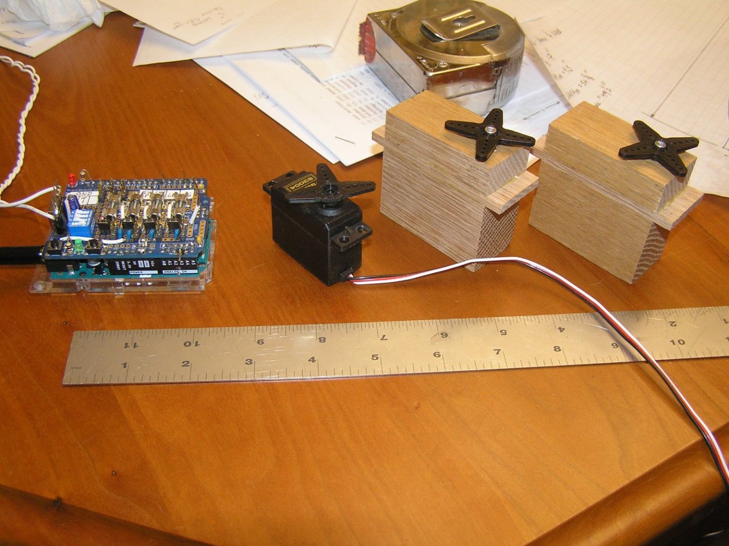
Welcome to those skipping straight here from the start instead of plowing through the prolonged history of the mechanism development. Finally getting started on actual hull development. Very little is actually known for certain about these ships, and of course there are no lines drawings extant. I'm using Michael Pitassi's book "Roman Warships" and building on his reconstructions. I also have on hand the lines for the "Olympias" which is a recently constructed full size trireme designed by a naval architect with archaeologist input. Unfortunately I already know my u/w hull needs to be much deeper than that of Olympias to support the weight so I cannot simply employ her lines. 😭 Galley Model Parameters: 1/32 Scale. Approx 54" LOA for a ship of about 145 ft. Approx 8" WL beam. 44 oars per side, in two remes of 22, staggered. Interscalmium 42" in accordance with Pitassi. (this is spacing between oars in a reme). Sea trials of Olympias quickly showed that her interscalmium of about 3 ft was too cramped for proper rowing. The archaeologist had used an ancient measure for which several values existed during ancient times and the consensus is the selected value was too small. Powered by a 5-cell NiMH battery producing 6V for the servos, and a 9V battery to power the Arduino Uno and RC Rcvr. Two oar servos per side, one for "Sweep" motion and one for "Lift" motion. Lift servos are standard size; Sweep servos are "Giant Scale" for continuous torque expected, and heat dissipation. Oars are approx 8" with loom 1.5". Oar angles when in water are 17 and 24 degrees for the lower/upper reme. Expected displacement approx 17 or 18 lbs. Because of this the u/w hull will not be "realistic", it will need to be bulked up to provide the displacement volume. I made a couple of mock-ups of the "giant" servos compared to standard-sized servos. I need these to make sure there is sufficient space at the bow to house them. Here is the Arduino "Uno" microcontroller board which runs the software to control the oars, with my servo interface board plugged into it; a standard servo; and the mock-ups. That's about it for now. I'm sure I will be a while drafting.
- 536 replies
-
- 4
-
-

-
- Quadrireme
- radio
- (and 1 more)
-
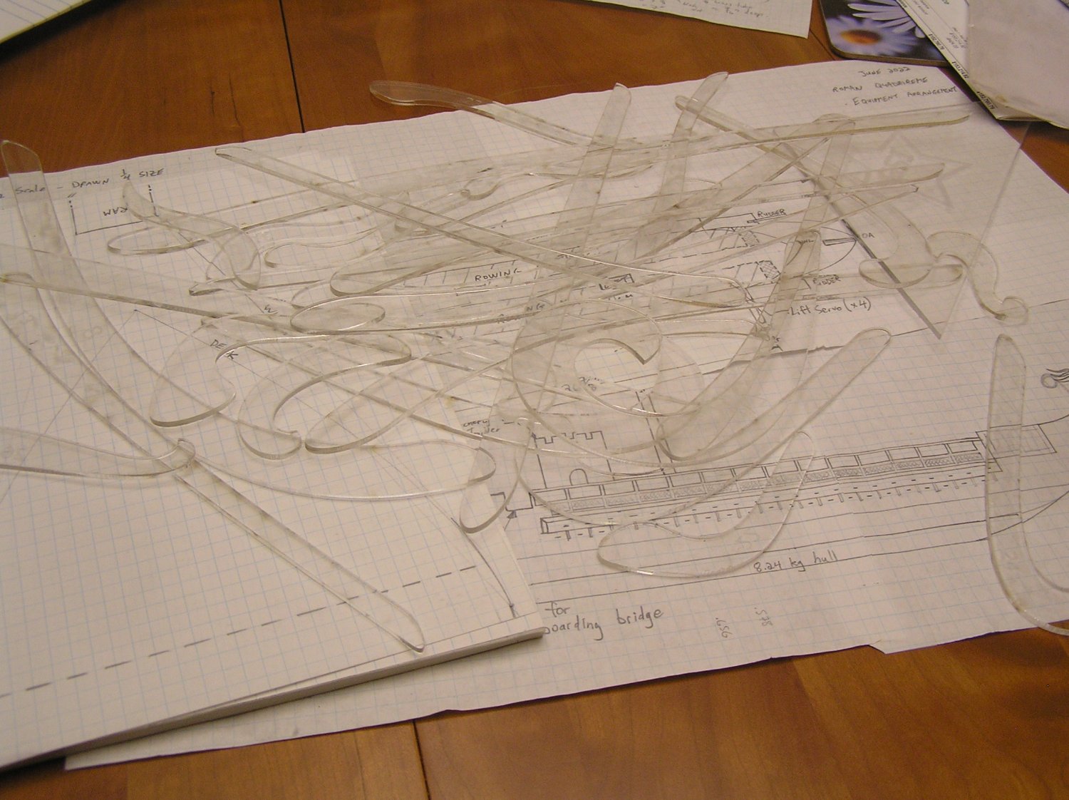
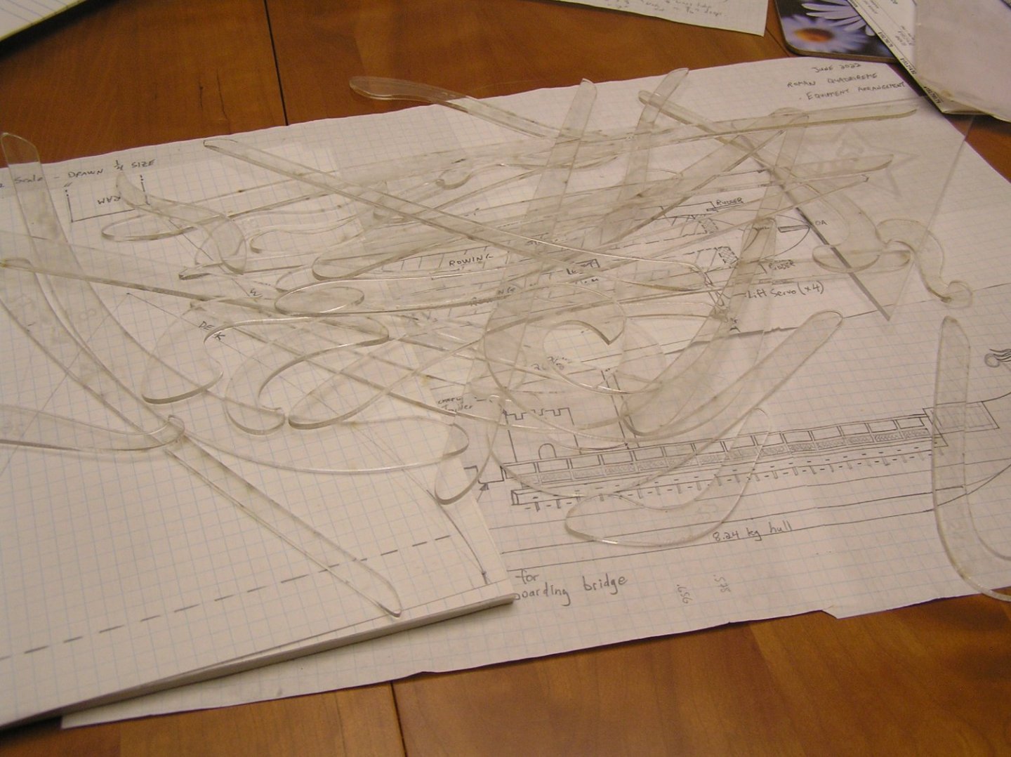
In order to draw the bow and stern lines, lacking any knowledge of or interest in mastering 3D CAD, I needed a set of ship's curves which are now rare and pricey. Member iMustBeCrazy kindly supplied to me a pdf file with 4 pages of images of a ship's curves set. I used it and our local library's "Imagine Space" laser engaver/cutter to produce my own curves using 1/8" thick acrylic. These cost me a grand total of $12 which the Imagine Space charges for a 12" x 24" sheet of 1/8" acrylic out of their closet. A steal!
- 536 replies
-
- 4
-
-
-
- Quadrireme
- radio
- (and 1 more)
-
Well, she did quickly sink - maybe when the wind gust hit they couldn't "let fly the sheets" because of this ...... 😄 Just being a smart alec........carry on!
-
Oh Glen, if you've never seen Blackadder, especially the Regency and WW I series, you have missed out. Look them up on Youtube! You'll never forget Lord Byron, the mad king, the coffee house, Dr. Johnson's Dictionary, the actors and "Macbeth", Blackadder's Jacobite Scottish relative (a particular highlight for me given my family name), then life expectancy in the RFC, meeting von Richtofen, Captain Darling, Lord Flashheart, .......... now I need to watch some episodes over again.
- 134 replies
-
- 4
-
-
- Captain Kidd
- bottle
- (and 3 more)