Ian_Grant
-
Posts
2,156 -
Joined
-
Last visited
Content Type
Profiles
Forums
Gallery
Events
Everything posted by Ian_Grant
-
 Impressive work with the i-beams and brass! But tell me (maybe I missed this earlier in your log?) why did they pile the lifeboats up like this? And how would they sway them out if needed? Thanks.
 -
Glen, you're a glutton for punishment, but as always this will be memorable to watch I'm sure.
- 134 replies
-
- 3
-

-

-
- Captain Kidd
- bottle
- (and 3 more)
-
Yes, I forgot that's all on the upper parts. Carry on ....
- 1,508 replies
-
- 1
-
-
- Le Soleil Royal
- Heller
- (and 1 more)
-
Bill, do you want to add some small evergreen strips on the inside of the gunwales at the railings, to add some molding detail where Heller just made the molds flat? Best done before you glue the hull halves. Or at least fill and sand those ejector markings which will be visible.
-
Could Mrs. AON be pranking you? 😀
-
Kevin, Rob Wiederrich's beautiful "Great Republic" scratch build is a great resource for clipper rigging, with many good photos. He has detailed rigging photos. I recall his chain sheets in particular because he formed his sheet blocks on the centre bands from brass. I tried it for "Preussen" but at 1/150 I could not do it. 😭
- 444 replies
-
- 1
-
-
- Cutty Sark
- Revell
- (and 2 more)
-
Curious about your plan to waterproof deck access hatches for the RC equipment.
-
Hi Kevin, That's Revell's rendition of the cheek block for the sheet line to the sail above. The fairleads on the lower yard are for the chain sheets to the lower topsail; on the lower topsail yard they're for chain sheets to the upper topsail. Sheets run from the sail's clew corner, through the cheek block, through the fairleads, and finally through the sheet block at the centre band and down to deck.
- 444 replies
-
- 1
-
-
- Cutty Sark
- Revell
- (and 2 more)
-
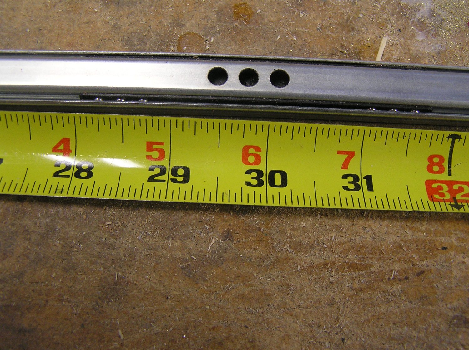
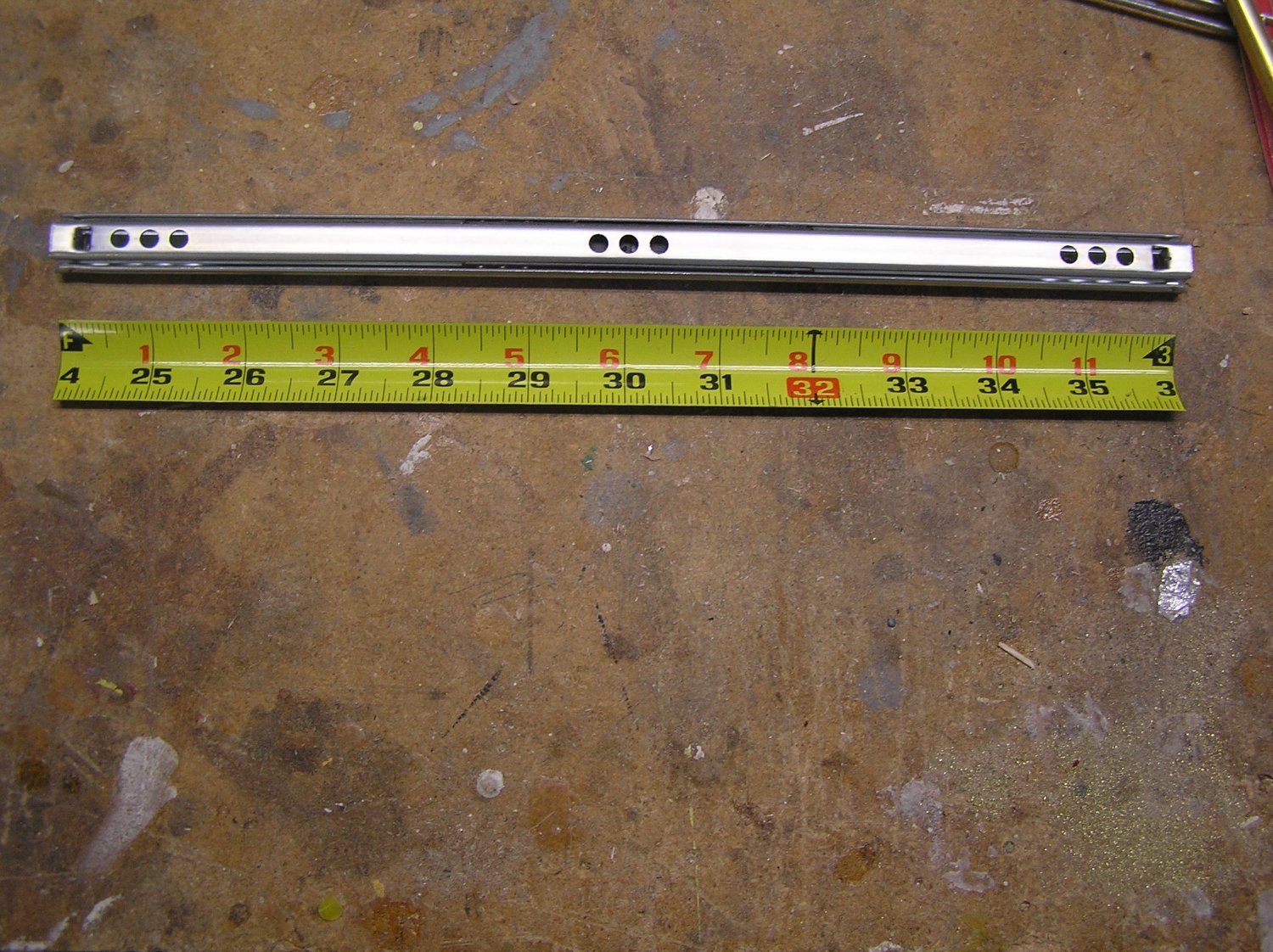
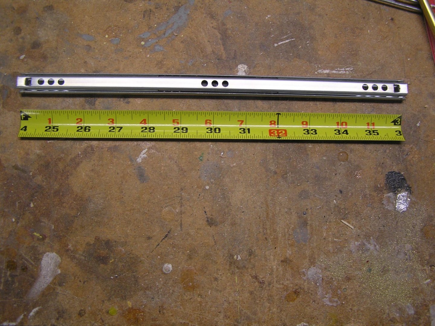
It has dawned on me (God my aging mind is getting slow!) that I can save some weight on the slides. I only need them to move 3/4" each side of "neutral"; I'm not pulling out a deep drawer so I could cut off a lot of their ends. For instance here is a close-up of a 12" slide: The actual BB carriage is only about 3.5" long, and if I move the metal slide 3/4" (say) the carriage only moves 3/8" in that direction since it is moving relative to both sides of the slide. I could in theory just cut the metal parts off 3/8" beyond the carriage ends with the slide centred, and drill new mounting holes i.e. I'd be left with "mini-slides" 4.25" long thus losing almost 2/3 of the weight! Like having my cake and eating it too.... I won't cut it that fine but losing a little more than 1/2 the weight of metal is easy to do. I'm going to the library tomorrow to take their one-on-one certification course to use their laser cutting/engraving machines. Just need to figure out InkScape to draw the ship's ribs 😬

- 536 replies
-
- 5
-
-
- Quadrireme
- radio
- (and 1 more)
-
Bill, when you do start the cannons be aware that they're a little strange as supplied. The trucks (wheels) are too close together and the trunnions are too far forward on the barrels. Assemble the carriages with the trucks closer to the corners, and if you're up to it cut off the trunnions and drill new holes through the barrels using a jig on your drill press. Dafi had good before and after shots of some cannons he modified.
- 1,508 replies
-
- 1
-

-
- Le Soleil Royal
- Heller
- (and 1 more)
-
Nice. And I see a winch drum there too. Hitec?
-
"diagonal knees" I haven't heard of up to now. Is that something special to "Constitution"?
- 64 replies
-
- 1
-
-
- Revell
- Constitution
- (and 1 more)
-
Scott, Wire for the standing rigging would be typically a little under 1.5"DIA for lower and topmast stays, about 1.0"DIA for topgallant stays, a little less for royal stays. Lower shrouds and topmast backstays same as lower stays for fore and main, same as topgallant stays for mizzen. Topgallant backstays on each mast same as its topgallant stay. Royal backstays on each mast same as its royal stay. So the scale thread sizes would be 0.375mm, 0.25mm, and 0.2mm. Typical commercially available sizes are 0.1, 0.25, and 0.5mm unless you go somewhere like Syren Model Ship Company who have much larger variety. I got these typical numbers from "Rigging the Clipper Ship and Ocean Carrier" by Harold Underhill. Well worth picking up a copy.
- 44 replies
-
- 1
-
-
- Thermopylae
- Revell
- (and 3 more)
-
I think that is what is referred to as "brailed up" i.e. not actually tightly furled. Looks like they are just leaving port and have sails ready to drop once they are clear. You don't see the clew lines when sails are hauled up to the yards because the lines are within the bundled sail. I'm having trouble picking out the sheet lines - they should be entering the bulk of the sail somewhere midway along the bottom on their way to where the clew lines pulled the clew corners upward and inward. Nice picture! Where did you find it?
-
All you really need is an inexpensive dovetail saw, a marking guage, and a couple of freshly sharpened chisels. Nonetheless, I use a jig now too. Mine is just an economy jig; couldn't justify a Leigh jig for variable pin spacing 😢
-
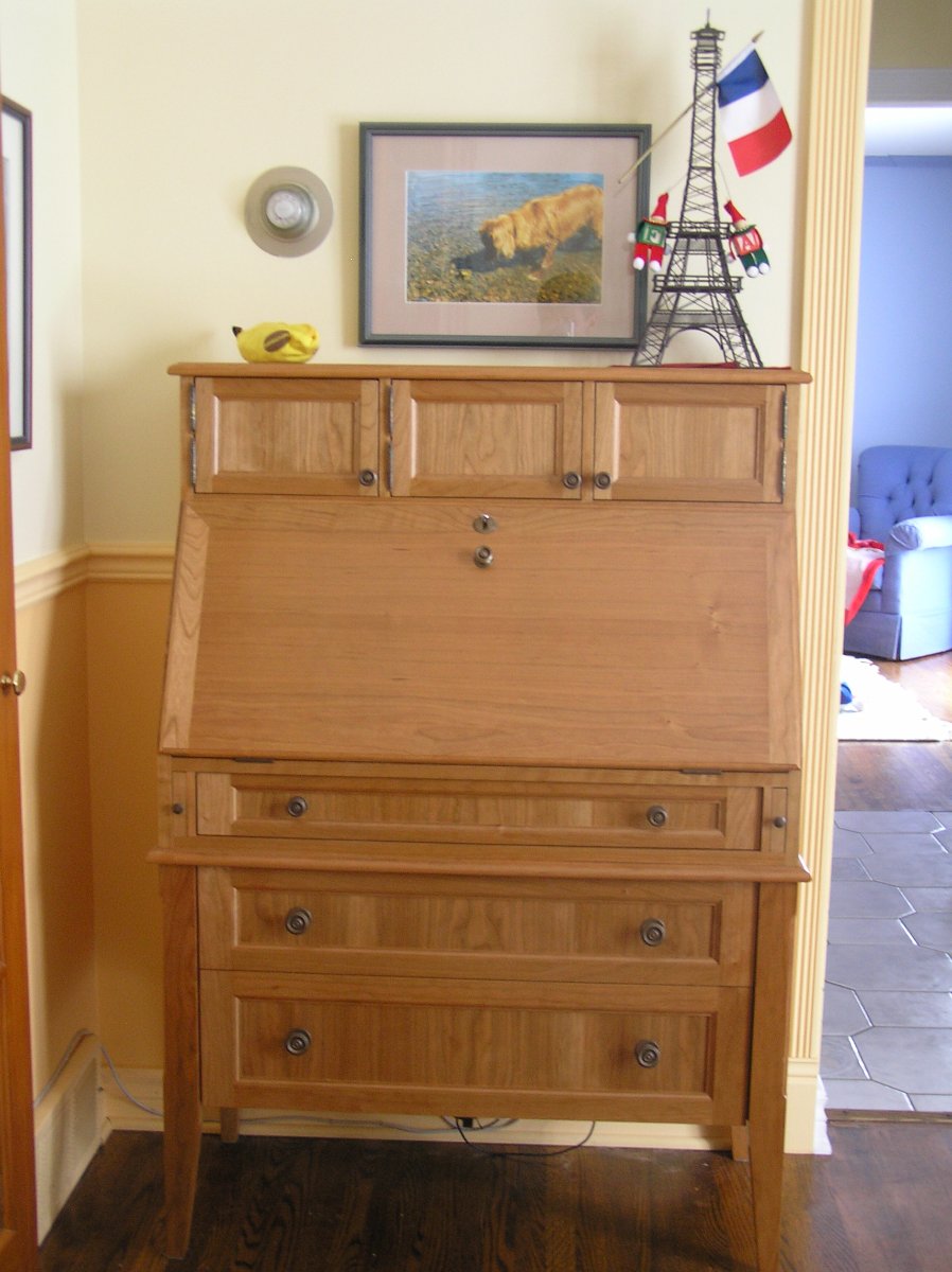
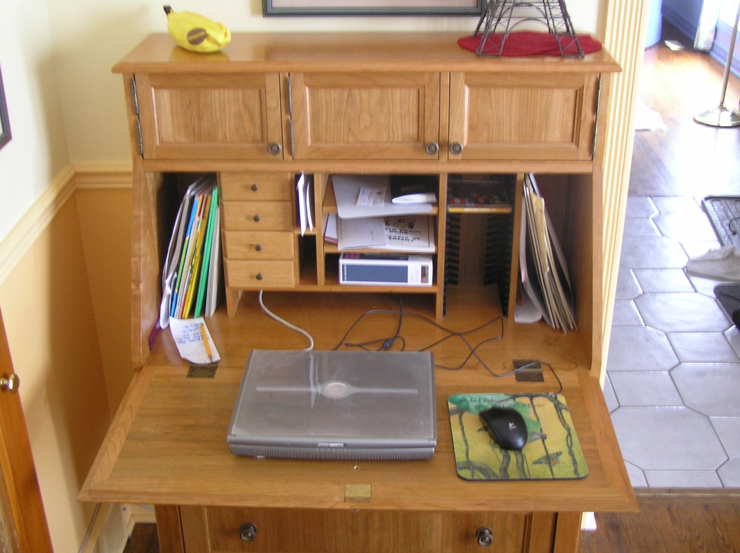
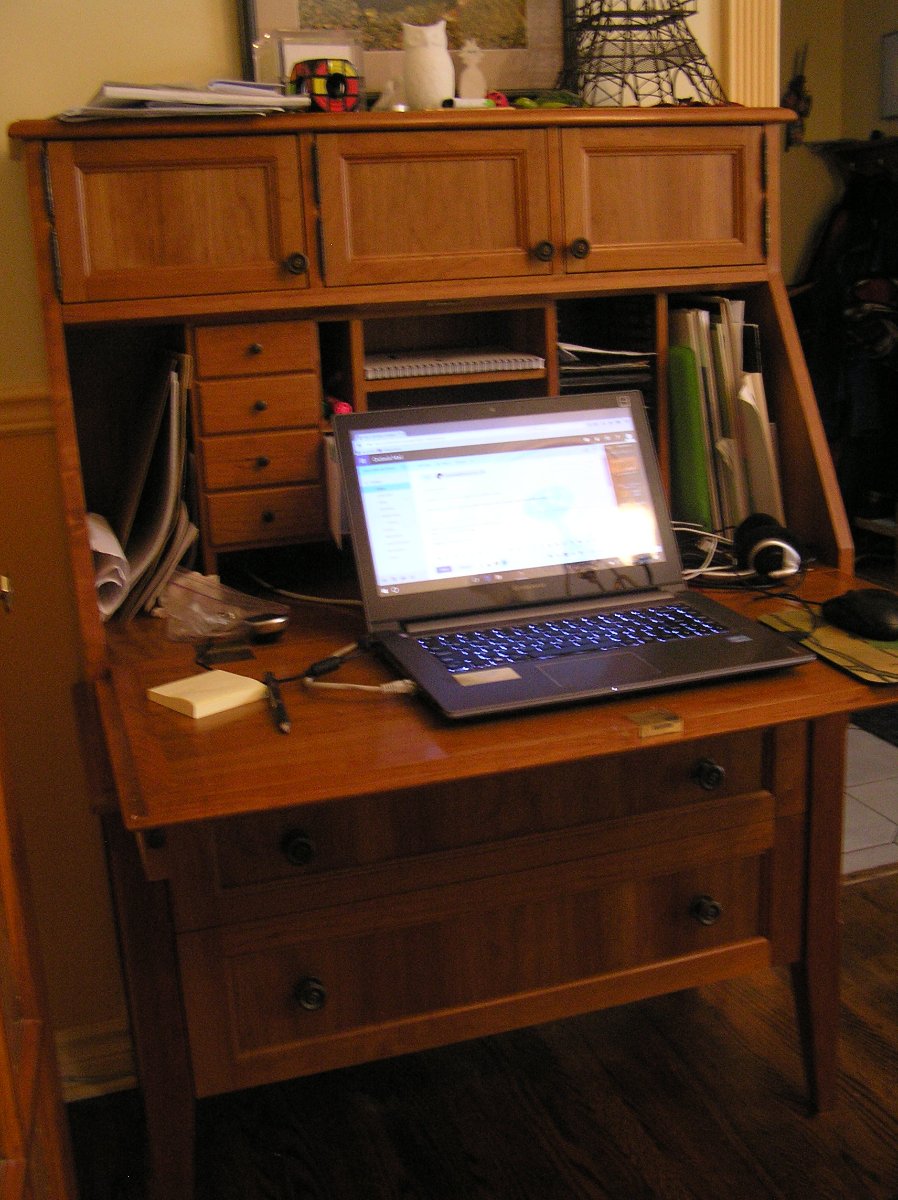
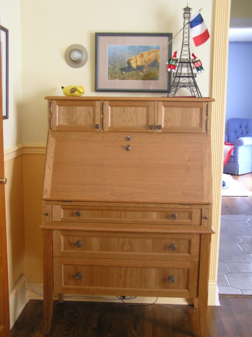
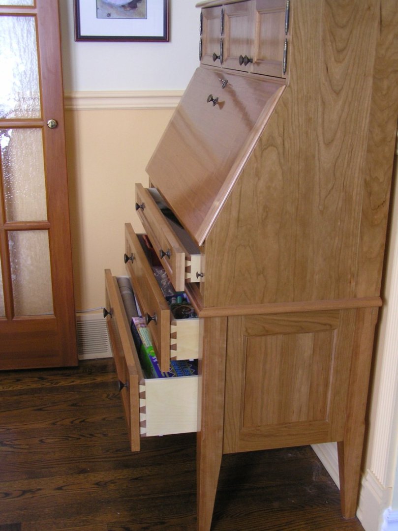
Bill you and I have much in common! One more project that I have photos of.....this desk that I am typing at. Cherry, which has become my favourite wood. It's nice to watch the wood darken and redden over time. First four shots are when it was new. Fifth is a more recent pic of its current glorious patina. All dovetails hand cut. We really must move to a new thread..........


-
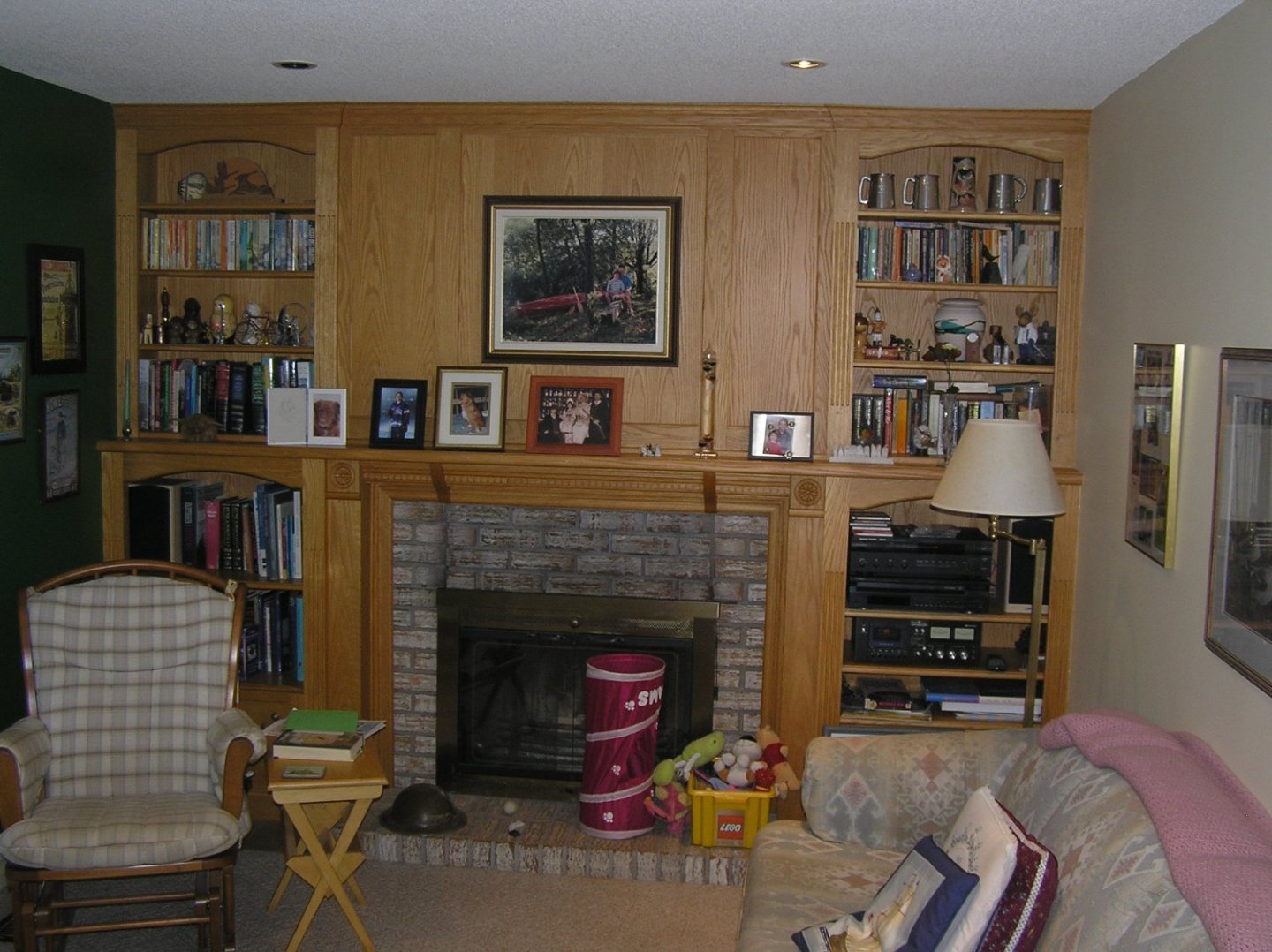
Yes I made the legs. Routered the flutes too. Here is the fireplace as it used to look with the old bricks. I did all the woodwork around it decades ago. Before that it was just a vertical column of bricks to the ceiling. I wanted to make this rather narrow room look wider by having the mantel span the lot, introducing a strong horizontal element. Excuse the mess.😬 If there's no furniture woodwork thread we could start one. I saw where one guy has his bathroom reno logged.
-
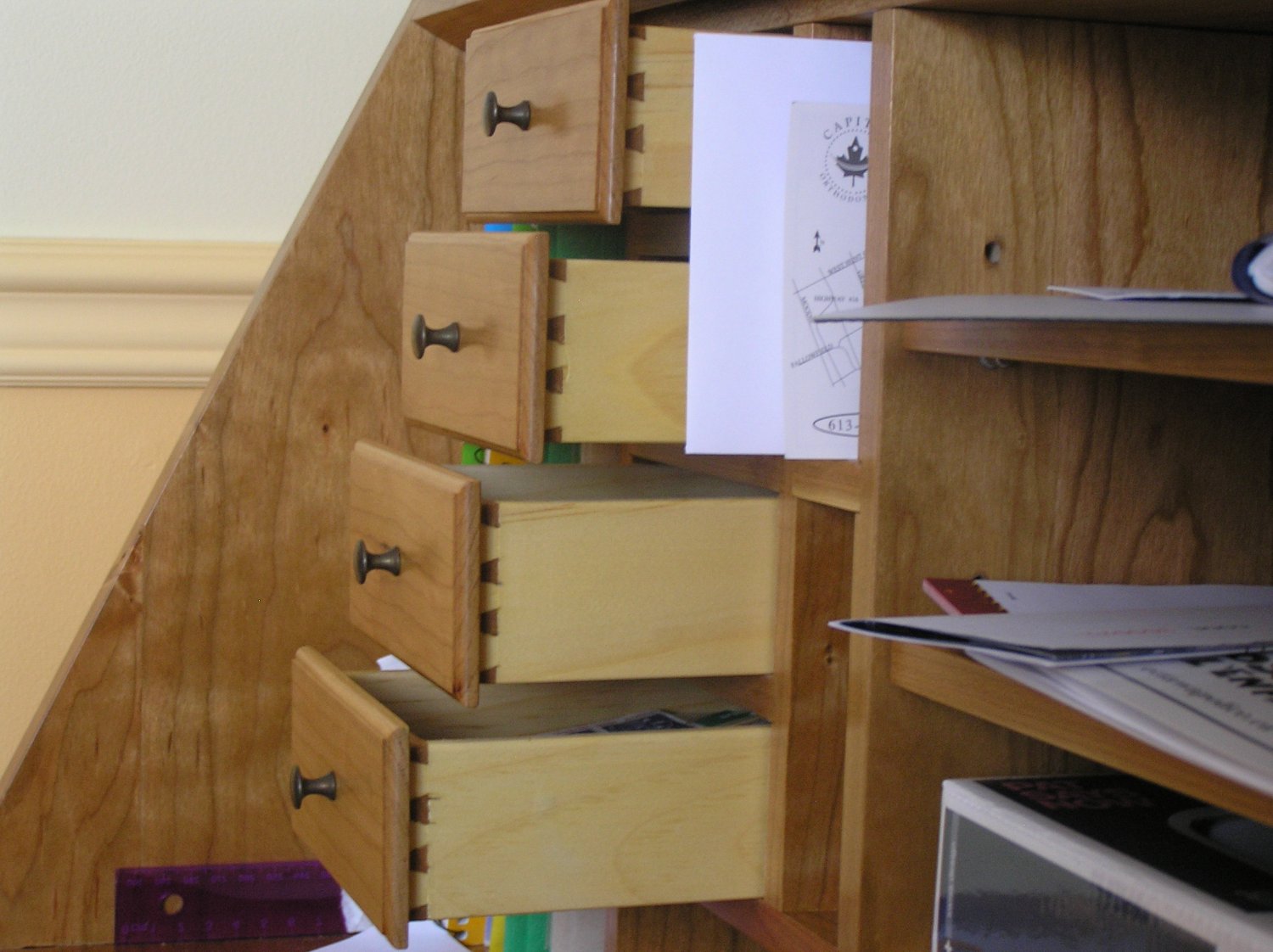
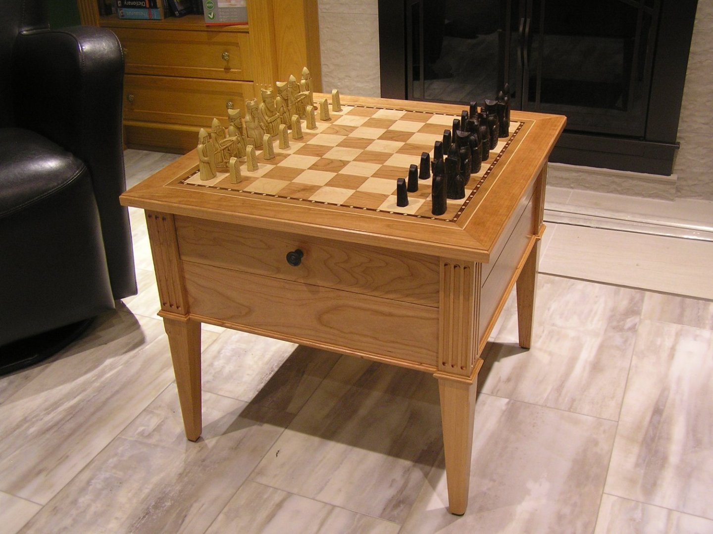
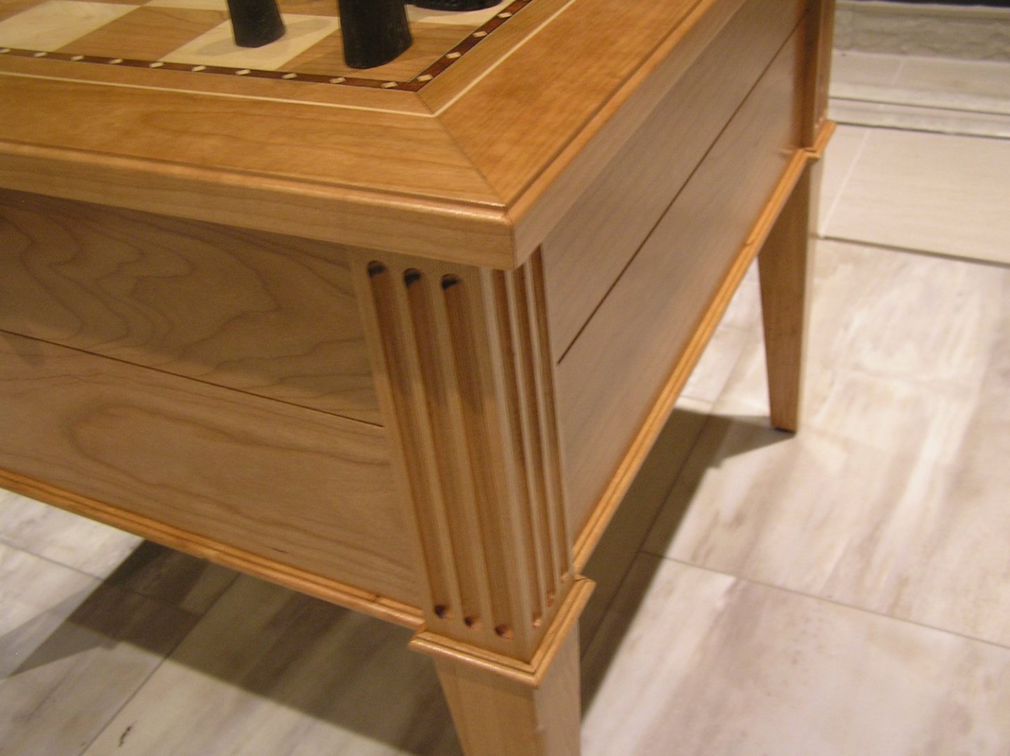
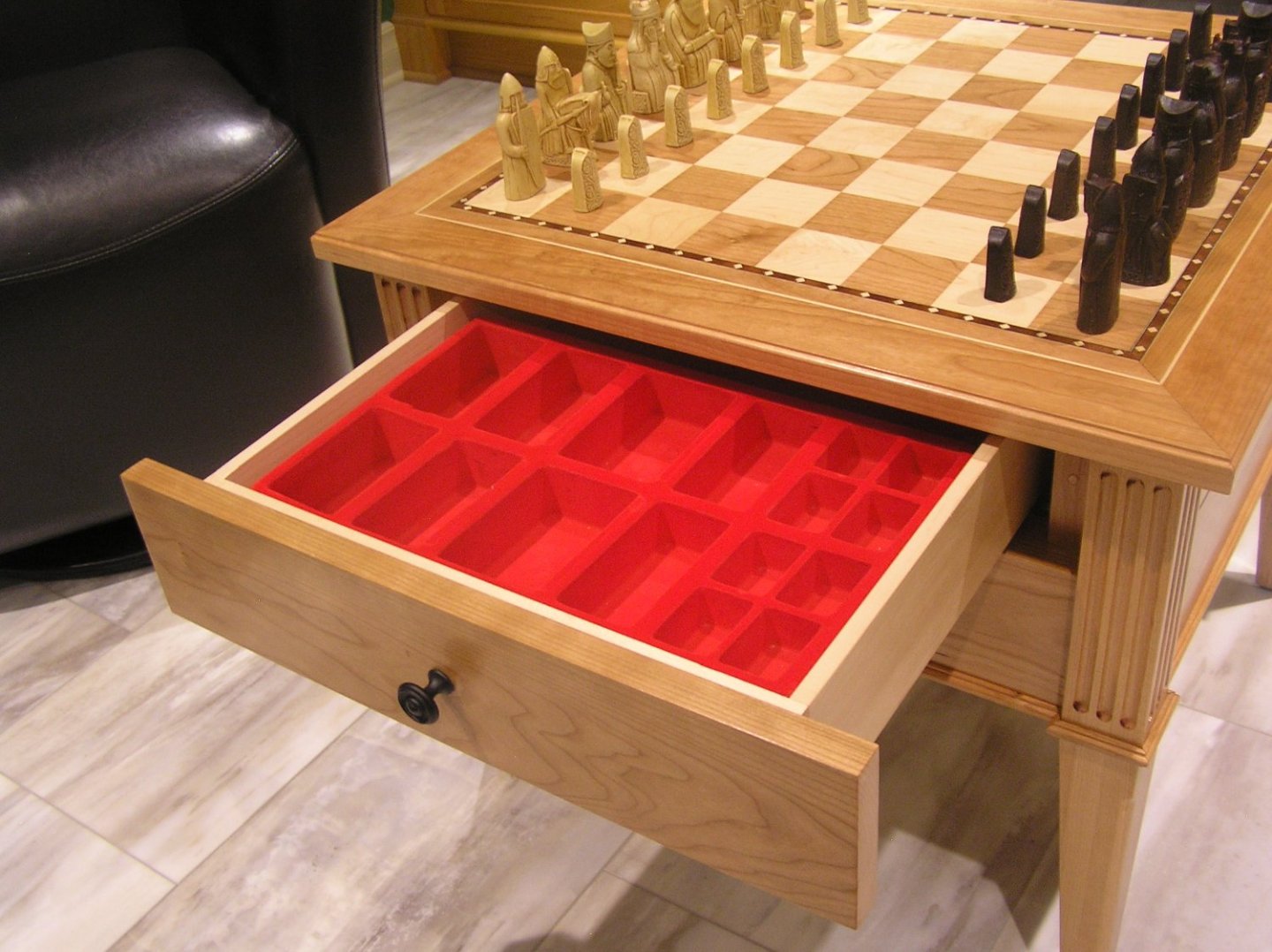
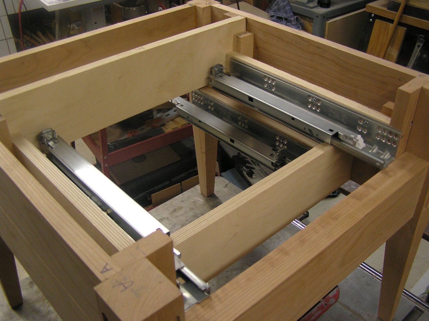
Bill, since we're trading woodworking tales, here are a few pics of my my last project: Chess table from cherry and maple. I'd been meaning for years to build one for a nice chess set I bought in Bavaria years ago but finally decided to do it when we re-did our family room. Also tiled over the old exposed bricks around the fireplace and installed new doors, and laid down vinyl interlock tile. The chess men came in a box, cradled in two layers in red velvet compartments. I sized the drawers to re-use these nice pieces. The drawers are stacked and open on opposite sides. It can't be seen but the corners are dovetailed using a router and jig. They use soft-close Tandem Plus slides ($$) which mount along the bottom, out of sight. Here are the slides during construction. The very fine trim around the bottom edge would have been wrecked by my 18ga nailer so it was a perfect excuse to buy myself a new pin nailer. What a great little tool - I didn't even fill its holes they're so small. The inlay around the playing field is banding from Lee Valley. I fell in love with this 12th century chess set when I saw it. Very viking-looking and I love the expressions on the faces. It's a replica of the "Isle of Lewis" set which was found on a beach where they had been buried. I've seen the originals in the British Museum.

-
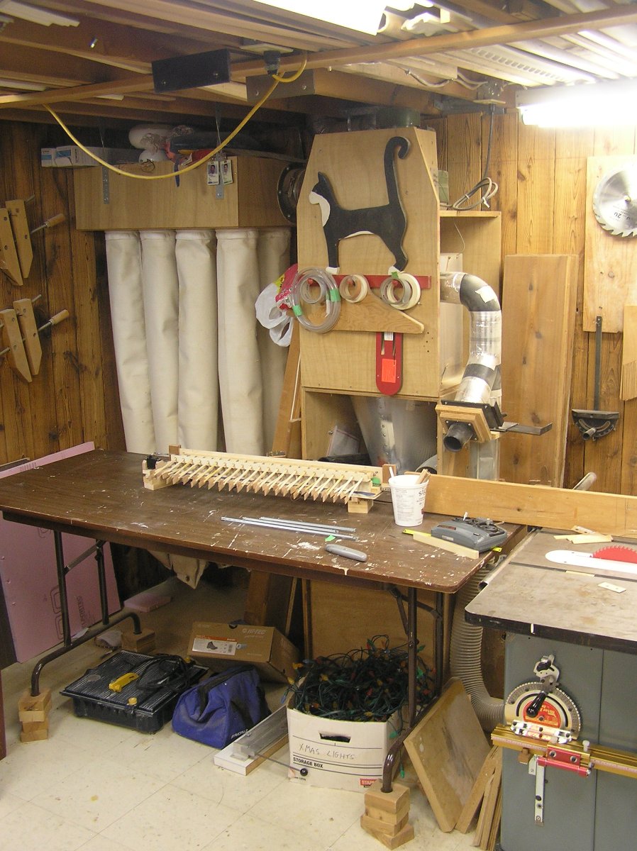
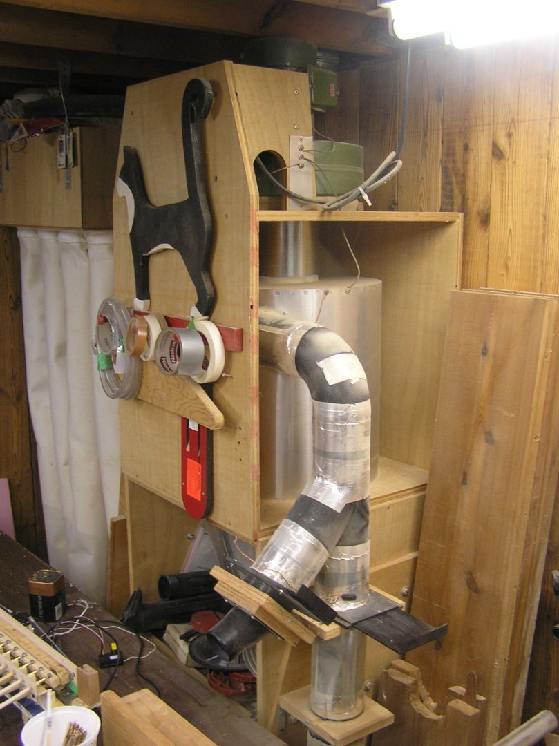
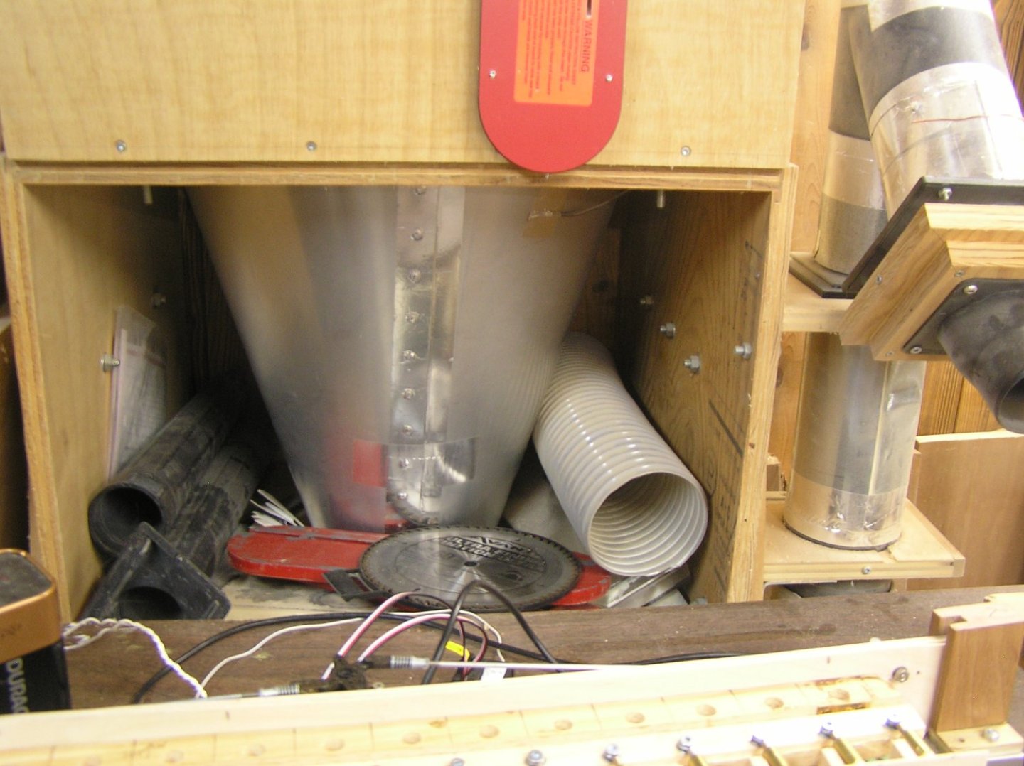
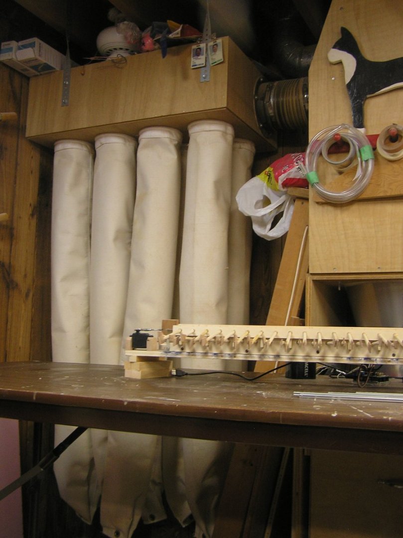
Thanks Bill, clear and understood. Yes, I have a complete wood shop including a 3hp Unisaw. I was interested to see your shop but I noticed you don't seem to have dust collection. I highly recommend a system of some sort. Many years ago I added dust collection with a home-built cyclone separator and final filter. This was after going to wood shows to shop for a system and seeing a puff of dust from the filter bags every time they turned their systems on. That demonstrated that fine particles were passing through their filter cloth, the very particles that can lodge in your lungs. Around that time an issue of Fine Woodworking had an article on cyclonic dust separators which included a photo of a guy feeding dust and chips into his separator's inlet port with a dustpan, with nothing visible coming out of its disconnected outlet. Lee Valley had a little book about dust collection with detailed math about pressures and flows and sizing ductwork. From this I learned that most of the systems you see for sale have insufficient outlet filter surface area for the airflow; if the pressure per square inch is too high then fine particles are blown right through the filter material. After all, it can't be airtight! That's why many syatems now have pleated bags which give some more surface area but really not enough still. I bought some "filter socks" from Oneida Air Systems which was just starting up at the time. A set of these gives vastly more surface area than any single bag, leading to lower pressure per square inch and no dust coming through. Hear are some shots of my system. The design for the cyclone I think was in an issue of "Woodsmith" but don't quote me. I bought a 1.5hp filter system just to get the motor and blower; the rest of the pieces I never used. The overll system sits next to my unisaw. Duct from saw to filter can be seen between saw and outfeed table. It's a very short connection to keep it efficient. The "y" connection allows connecting a hose from other machines. The sliding shutoff s select between the two. Detail of the inlet ducting. Green motor and enclosed fan are at the top. They suck air up the internal pipe in the separator. The conical part of the separator. Junk store all around it 😬. There's a removable collection bin on wheels beneath it. Fan duct to home-made plenum is at the top, keeping the connection very very short. Normally the plenum would be at the bottom with the socks held above it to allow dust to drop off into the plenum for cleanup but I decided minimal duct length was higher priority. Even after all these years there is very little dust accumulated at the bottom of the socks; hardly anything comes through the separator. I have to be careful to empty the collector bin outside, with a filter mask on, because there is always very very fine dust in it. Bill I recommend such a system. There are many available now including cyclone lids for standard garbage cans, although I don't know how well they work. As an aside, in a couple of these pics you can see my final prototype for the servo-driven rowing mechanism for an RC Roman galley I have been working on, 44 oars a side, sitting on the table. There's a video of this rowing, with water, in my last post about this prototyping. If you are interested just search for "Arduino" and my log will come up.

-
Bill I'm curious about the joinery in your case. For my Victory I had a local plastics place make me the four sides and top in plexiglass with no framing. In fact, the front/top/back are one piece bent on a radius to form the top edges. But this was quite costly. Next time I will build one too. Did you dado the plexiglass into the wood? How is all the wood joined at the top corners, given that your strips are small in cross section to keep the case airy looking?
-
That Airfix hull looks pretty nicely molded to me. I thought it was looked upon as inferior to the newer Revell of Germany Wasa? Or has Airfix retooled it?
-
Nice stern painting at this scale especially! I agree with shipman, it would be a LOT of work to cut out the windows to replace with etch. I didn't even do that for my Heller Victory.