Baker
-
Posts
4,276 -
Joined
-
Last visited
Content Type
Profiles
Forums
Gallery
Events
Everything posted by Baker
-
I found this buildlog on a Dutch forum. Impressive model. Of course with Dutch text but with nice pictures. http://www.modelbouwforum.nl/threads/hms-victory-caldercraft-1-72.205911/ http://www.modelbouwforum.nl/threads/hms-victory-caldercraft-1-72.205911/page-23
-
 Beautiful planking. I have the same idea to use Plexiglas as a base. But I have not reached that point yet. I am therefore curious about your working method and the result. Good work.
 -
And greetings from Belgium
-
Thanks, I'm doing my best. LOL 😂 I do not like sports. The only "sport" i do is rifle shooting (completely legal according to all Belgian laws of course!!)
- 756 replies
-
- 1
-

-
- galleon
- golden hind
- (and 2 more)
-
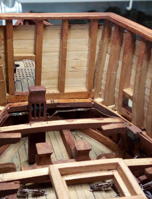
The following parts are ready and installed. From now on, the shipyard is on hold for a while. I have had pain in both arms for some time. Doctor's conclusion: tennis elbow on both arms, so rest for a while, no model building, no gardening... grrrr. Thanks for following, And it is not because the shipyard is on hold, that I will not be active on this forum
- 756 replies
-
- 6
-
-

-
- galleon
- golden hind
- (and 2 more)
-
Marius, I made holes in the hull and then glued the gunport surrounds into these holes. Then they are sanded flat with the hull. Ik maakte gaten in de romp en kleefde daar de kanonpoorten in. Daarna zijn deze mee vlak geschuurd met de romp. I glued pieces of wood behind the gunports. This method proved to be very cumbersome. Gluing pieces of plywood between the frames is much easier, and paint the inside black. You can find this method in several logs.k Ik lijmde houten blokjes achter de kanonpoorten, deze methode is zeer onhandig. Lijm stukken triplex tussen de spanten en schilder deze zwart. Je vind deze methode beschreven in verschillende bouwlogs. Normally under the waterline, the color is white. Normaal is de kleur onder waterlijn wit One of the reasons why the Vasa sank so quickly was too little depth. Eén van de redenen waarom de Vasa zonk was te weinig diepgang.
-
this ? http://modelshipworldforum.com/resources/Rigging_and_Sails/ScaleSails.pdf
-
Welcome, and greetings from Belgium
-
Welcome, and greetings from Belgium
-
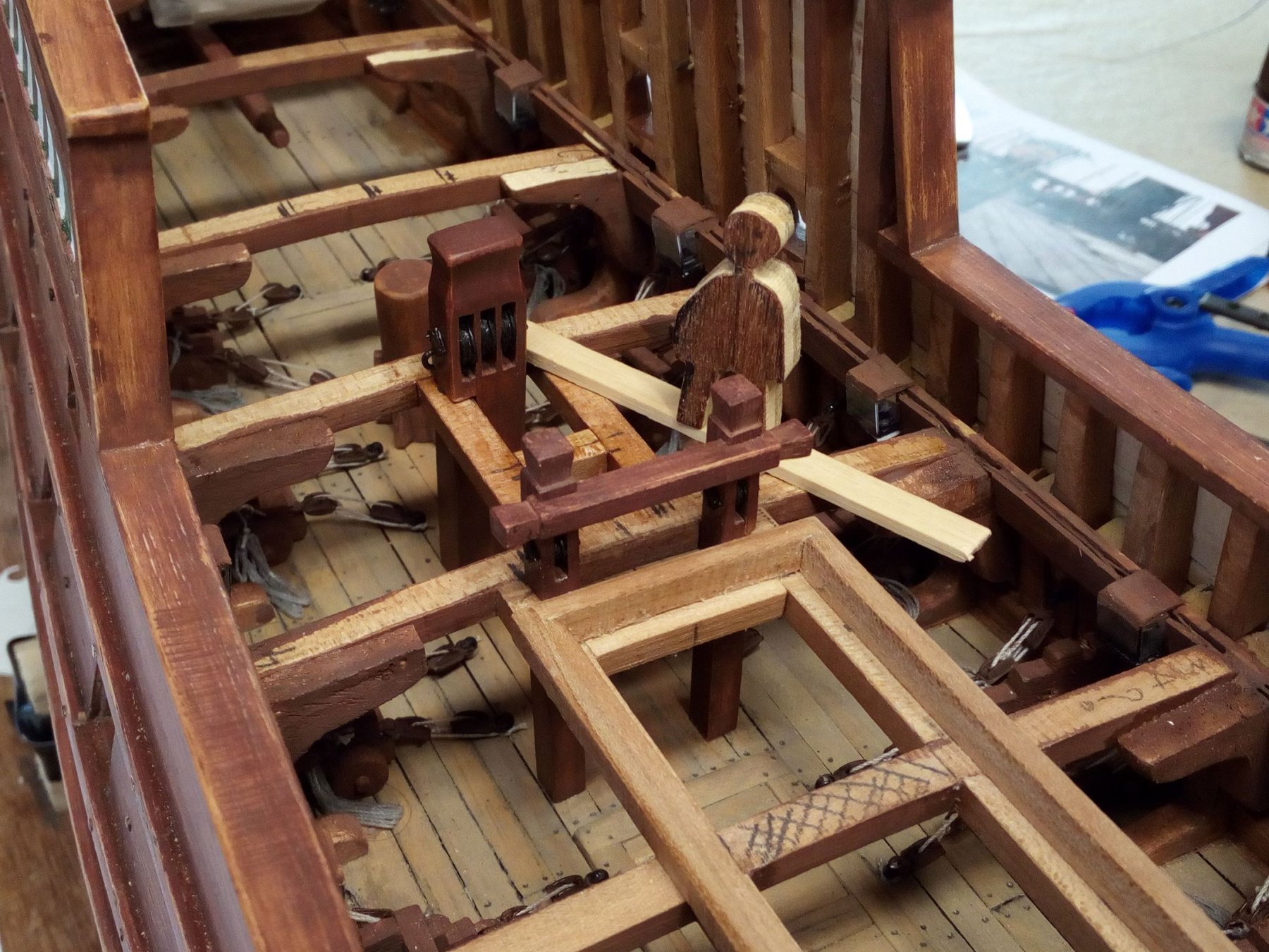
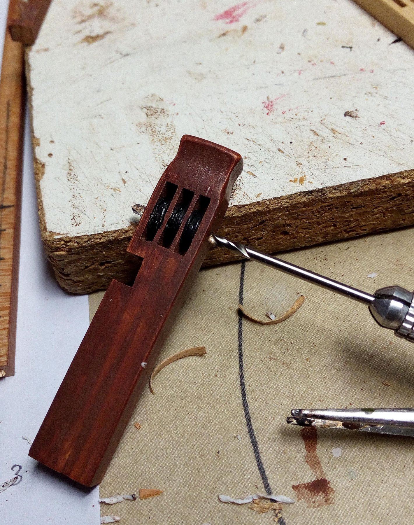
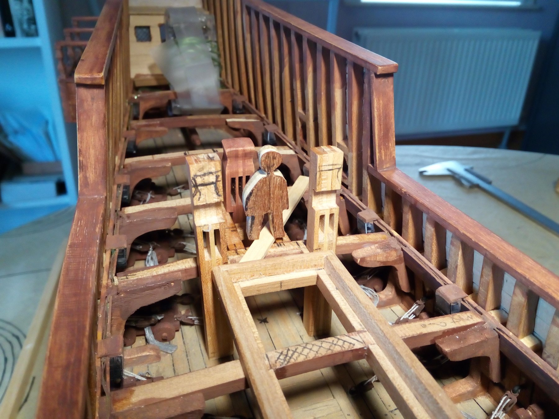
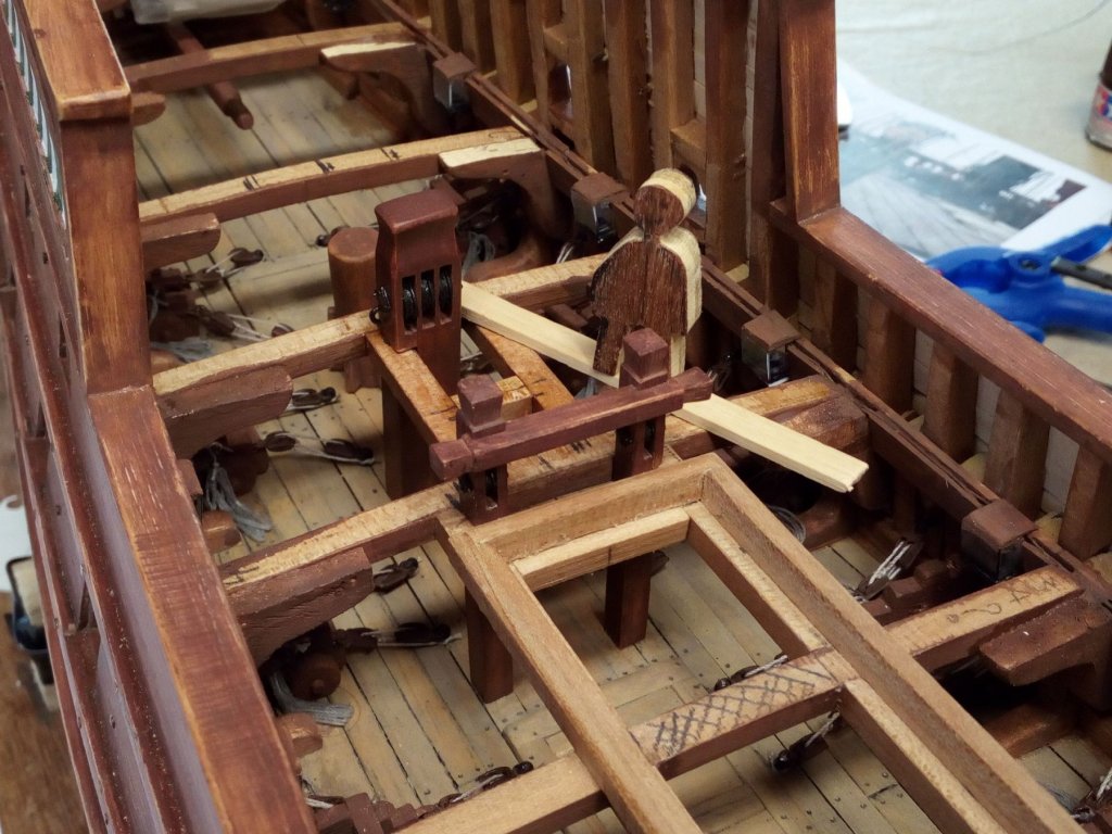
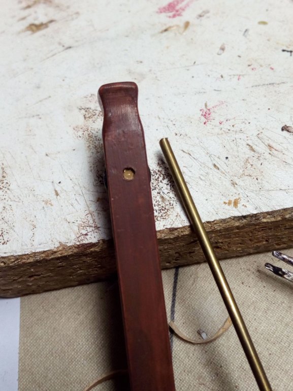
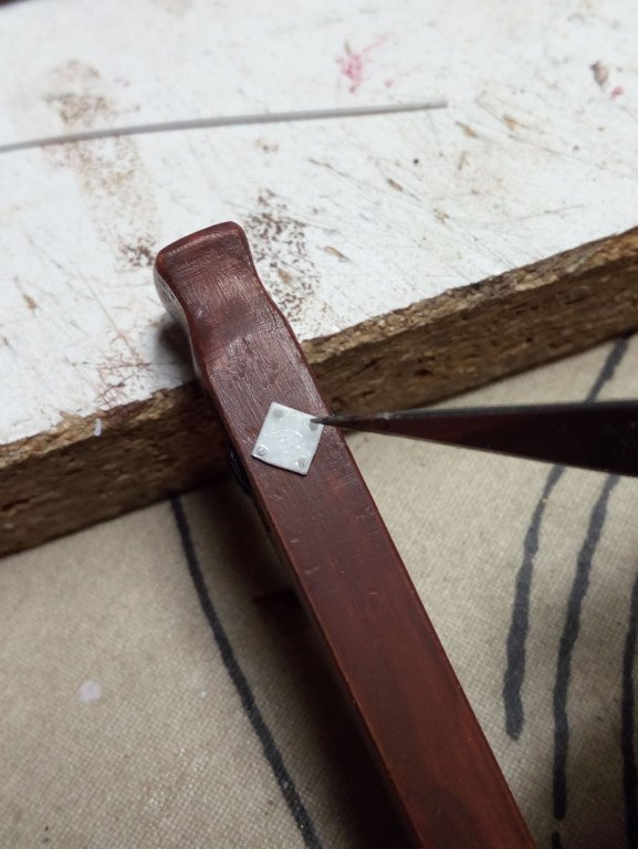
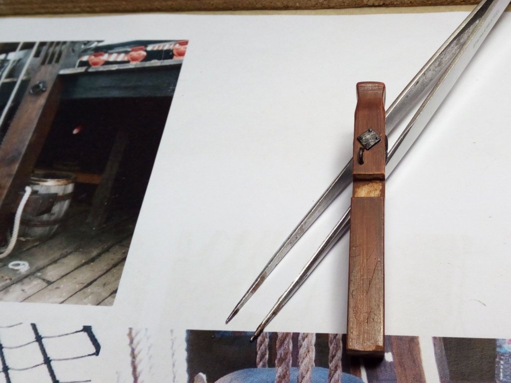
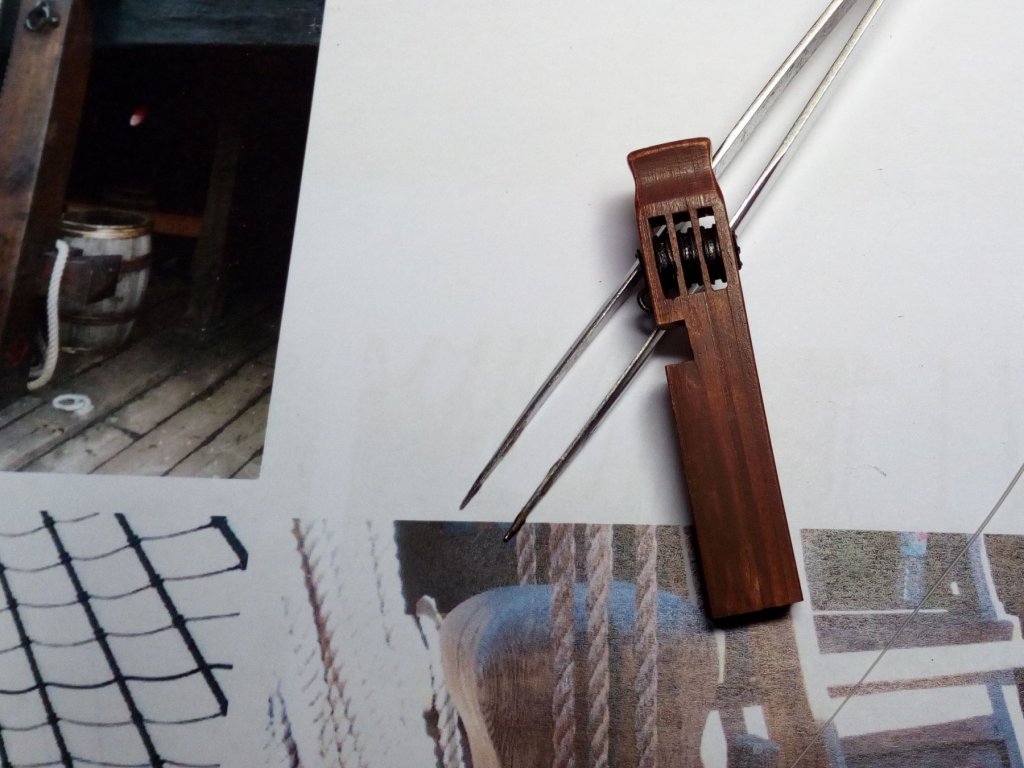
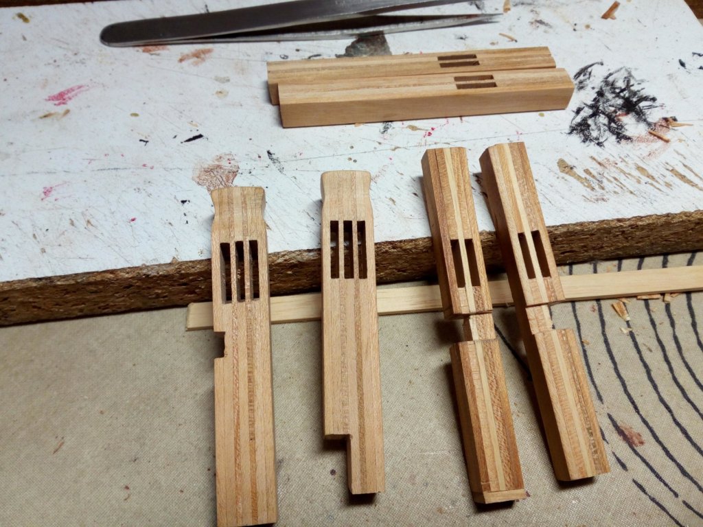
Hello, Started with re-making the wrongly made pieces. The same method has been used to make them. The discs are made of plastic. After painting, the discs are mounted without glue. The hole is now also being drilled trough the discs. That way I drill in the center of the disk. And secured with a brass pin. Extra detail painted and ready for assembly. The height ratio of the piece to the model and the size of my assistant is much better now. To be continued. Thanks for following.


- 756 replies
-
- 11
-
-
- galleon
- golden hind
- (and 2 more)
-
I think this is a great idea 👍
-
Greetings from someone who also can not translate without google
-
Greetings from Belgium
-
Beautiful work. I am still jealous of your drawing skills as preparation .
- 219 replies
-
- 2
-
-
- smack
- cross-section
- (and 2 more)
-
Looking good, Good luck with the filling and sanding.
-
looks great . Congratulations Greetings, Patrick
-
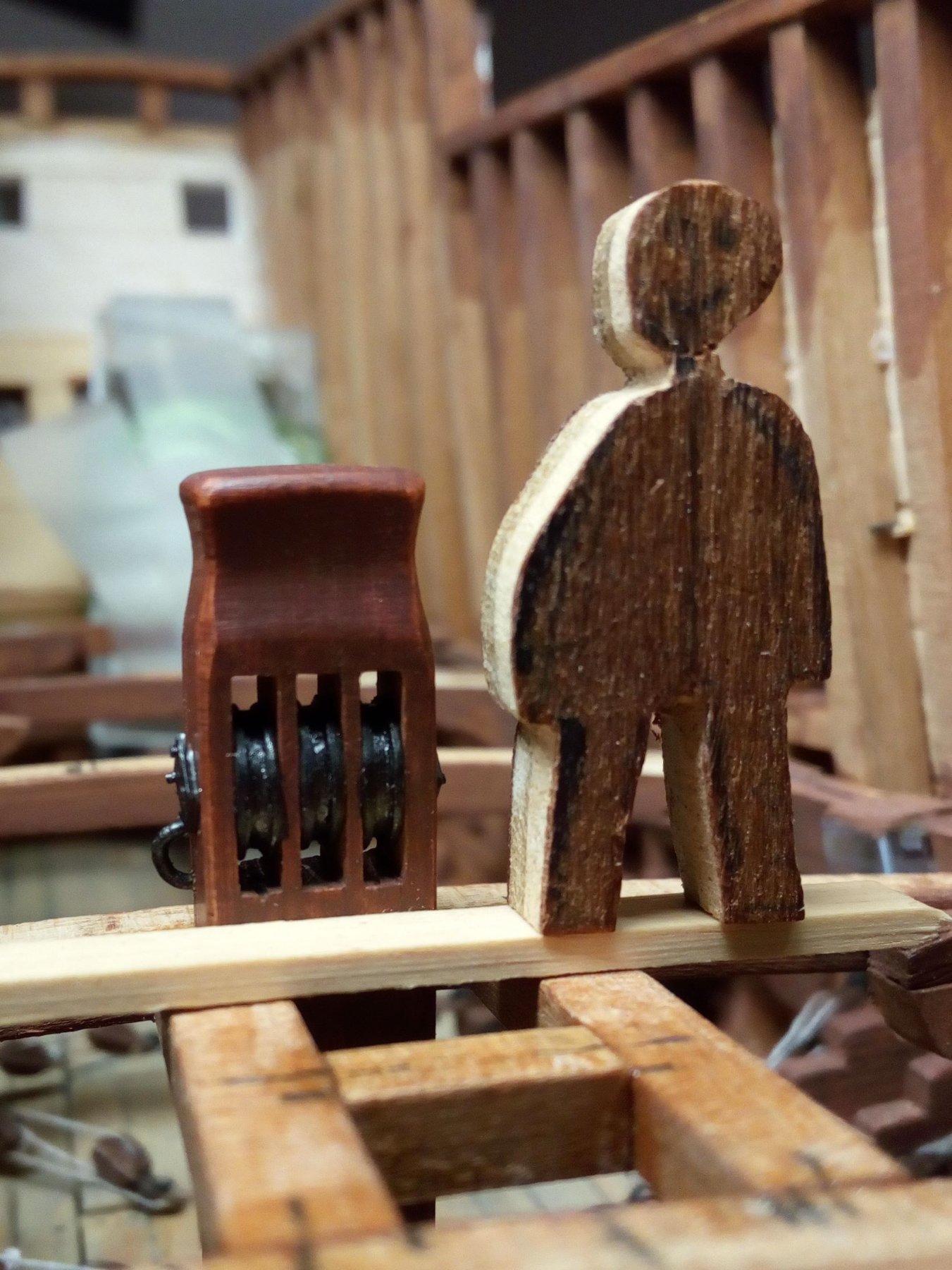
Thanks steven. The average length of a man in the 16th century may have been 160 cm. 160 cm : 45 = 3.6 cm to scale
- 756 replies
-
- 3
-
-
- galleon
- golden hind
- (and 2 more)
-
Greetings Patrick
-
greetings patrick
-
Yes. The stairs will look like this greetings, patrick
- 756 replies
-
- 1
-
-
- galleon
- golden hind
- (and 2 more)
-
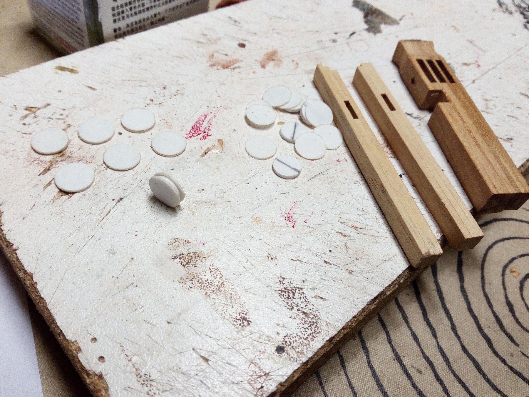
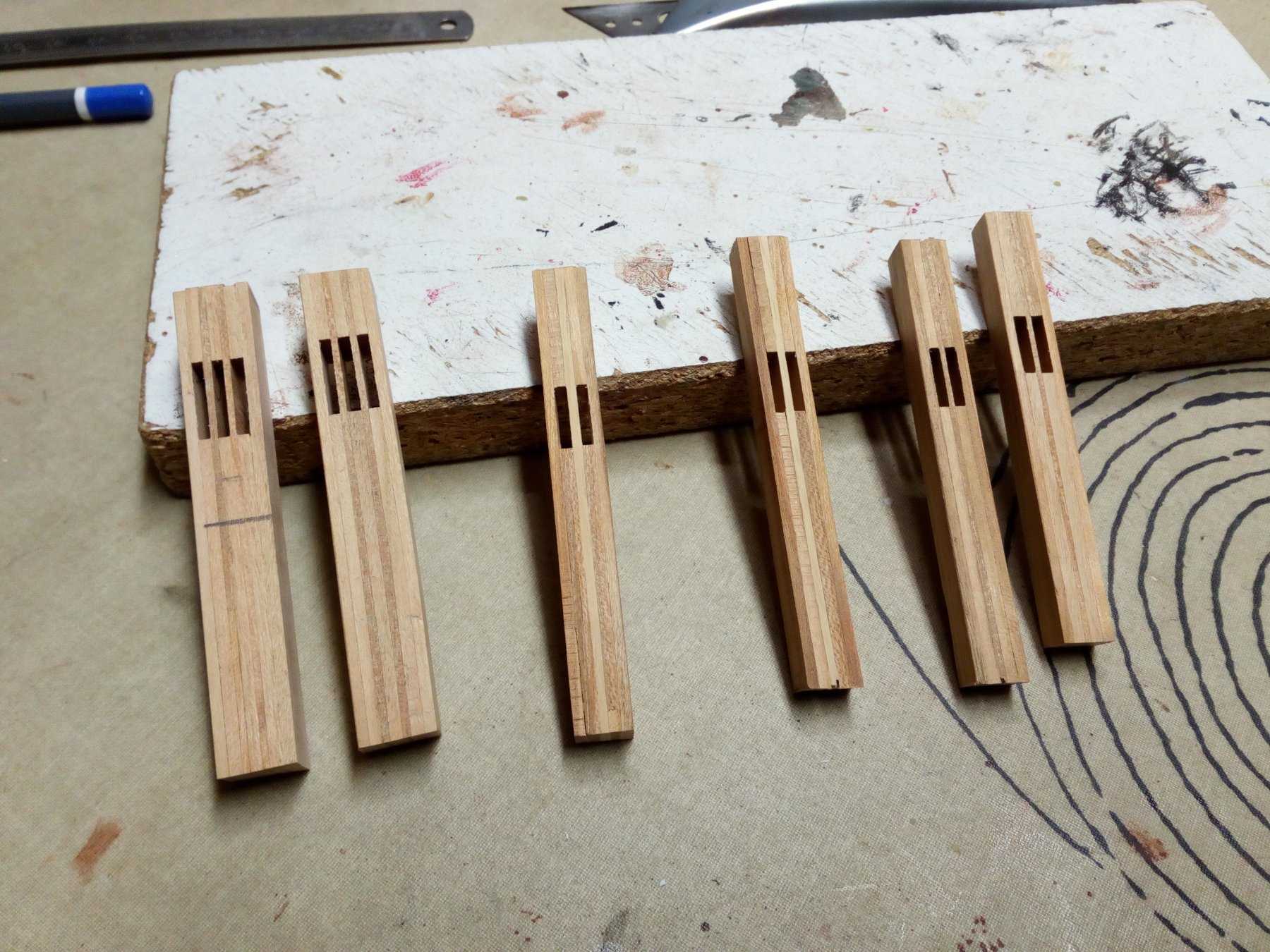
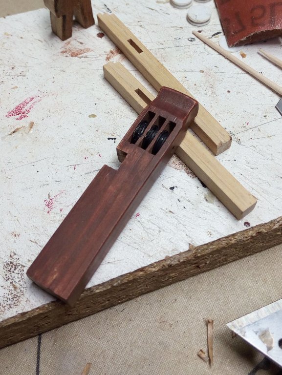
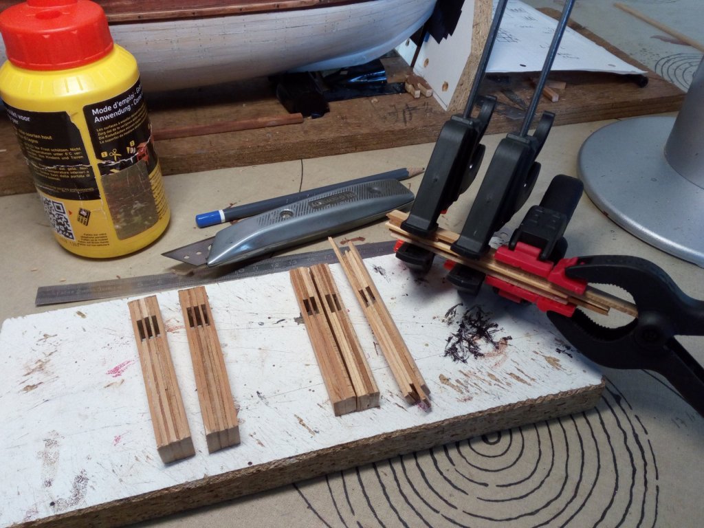
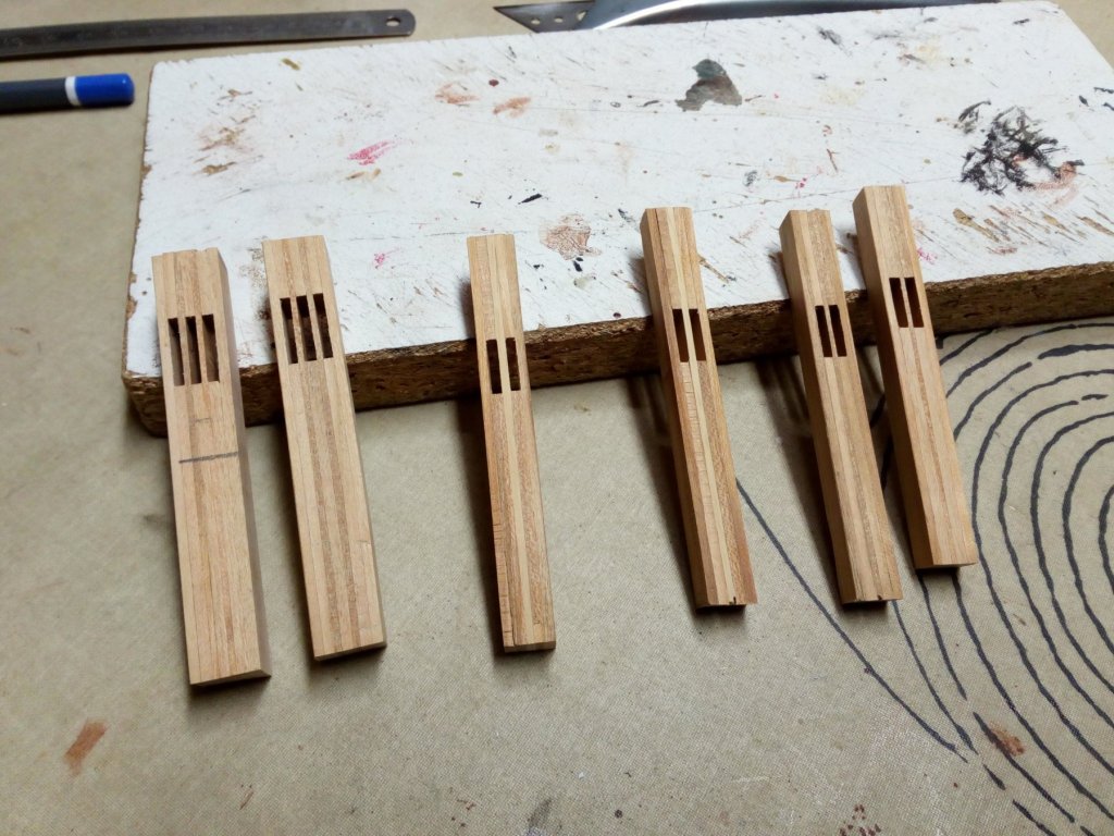
Hello, I made these pieces last week. Everything looked good, but I felt something was wrong. I made the pieces too big. They are not in proportion to the model. I also discovered that my cherry wood is not suitable for this application. The wood differs too much in color So redo. Better and smaller next time

- 756 replies
-
- 5
-
-
- galleon
- golden hind
- (and 2 more)
-
Started without me? I take a chair and watch and learn.
- 219 replies
-
- 1
-
-
- smack
- cross-section
- (and 2 more)