HOLIDAY DONATION DRIVE - SUPPORT MSW - DO YOUR PART TO KEEP THIS GREAT FORUM GOING! (Only 13 donations so far - C'mon guys!)
×

tlevine
-
Posts
2,032 -
Joined
-
Last visited
Content Type
Profiles
Forums
Gallery
Events
Everything posted by tlevine
-
 So what I am doing is wrong, if I understand this correctly. There would only be a square copper head visible on the outside of the hull? Is Goodwin incorrect in his depiction of interior and exterior roves or was that technique specific to Alert?
 -
Druxey, then what is on the outside? I have drawings showing roves both under the bolt head and internally, where the bolt is clenched.
-
Greg, the bolt is only 0.5 mm (scale 1") in diameter and the rove is 1.25 mm, so their rivets would be significantly oversized. I will definitely try not to achieve step 6. But if I act strangely at the Annual Meeting, you will know why.
-
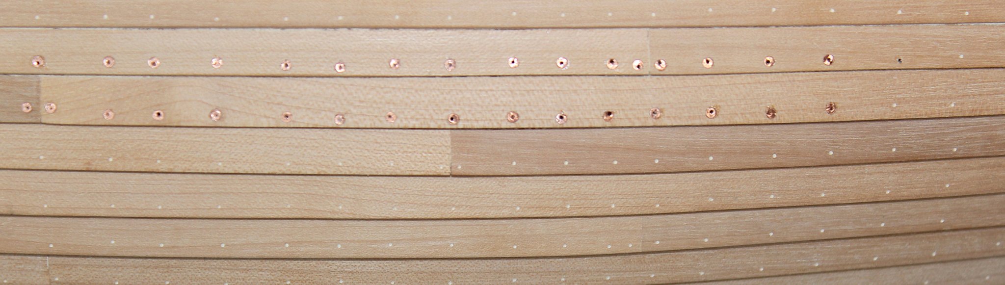
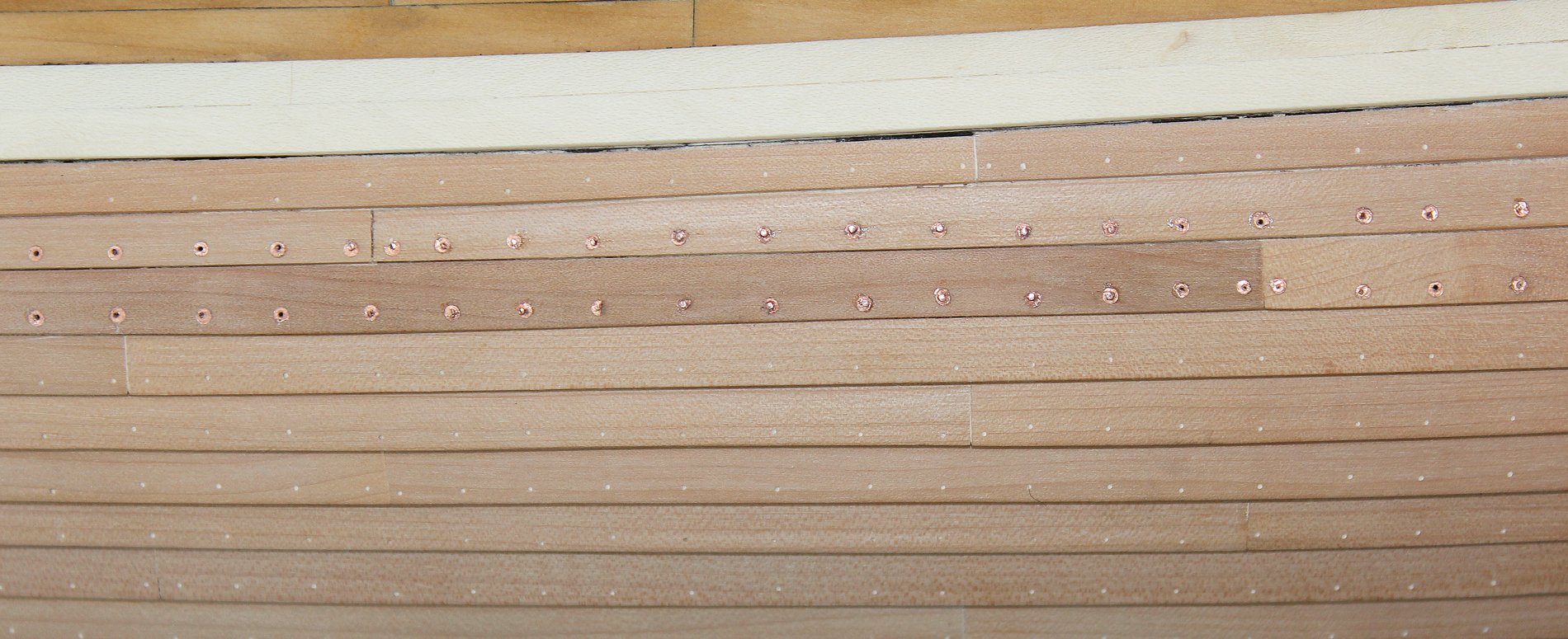
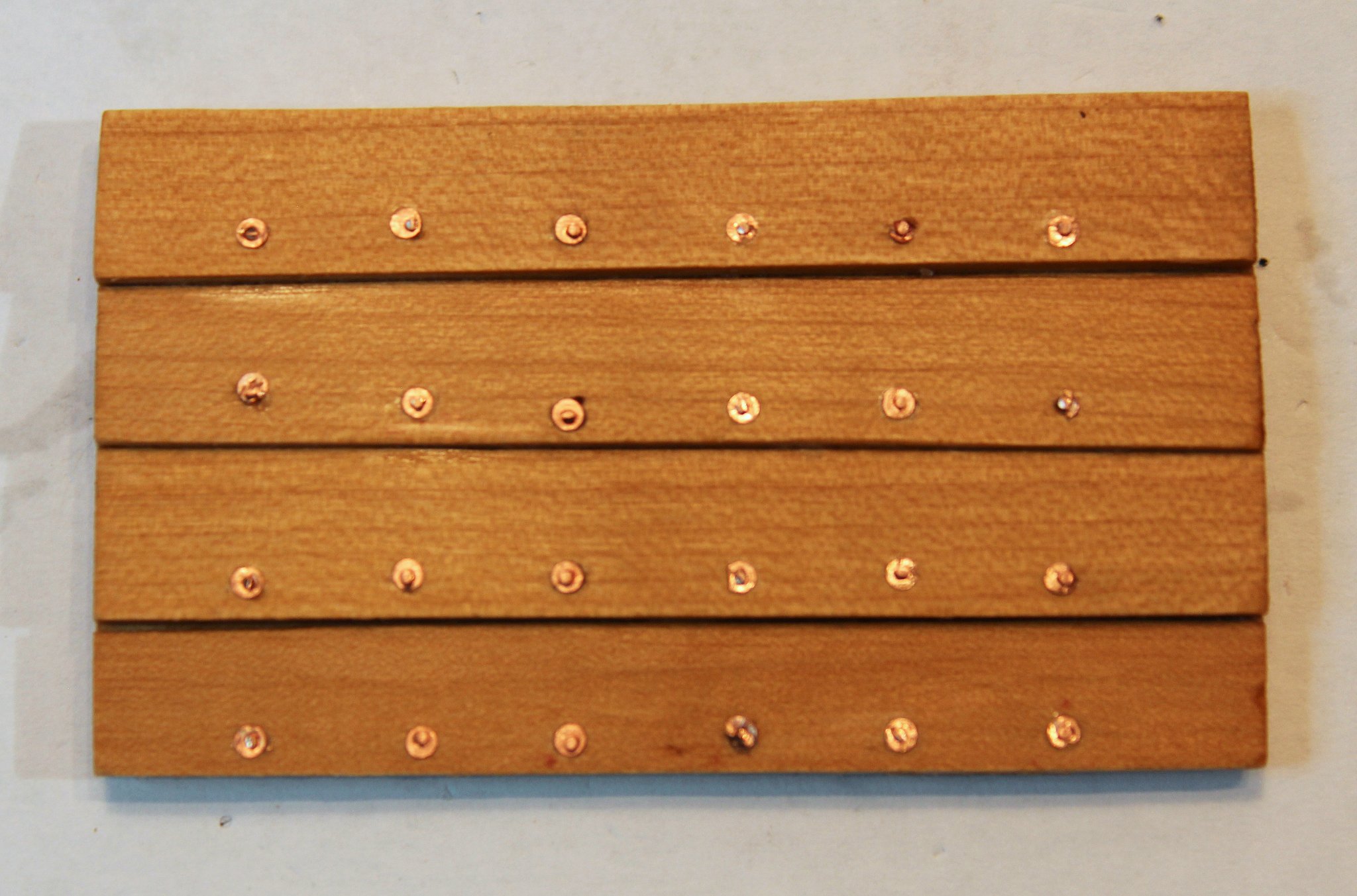
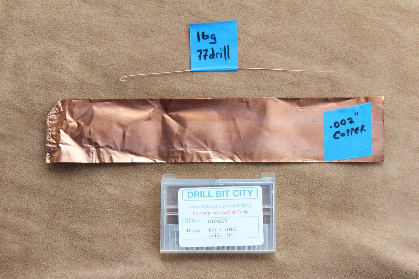
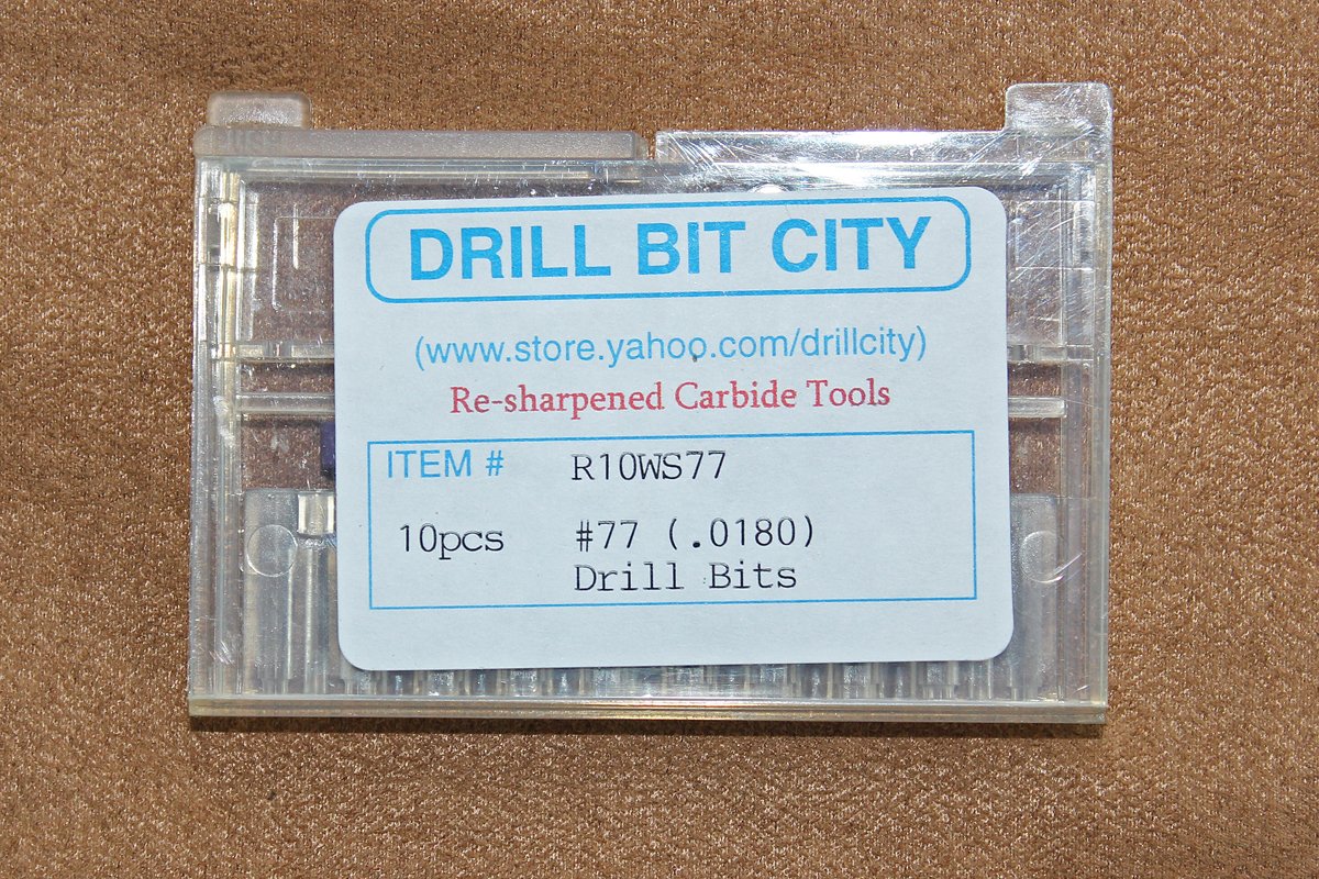
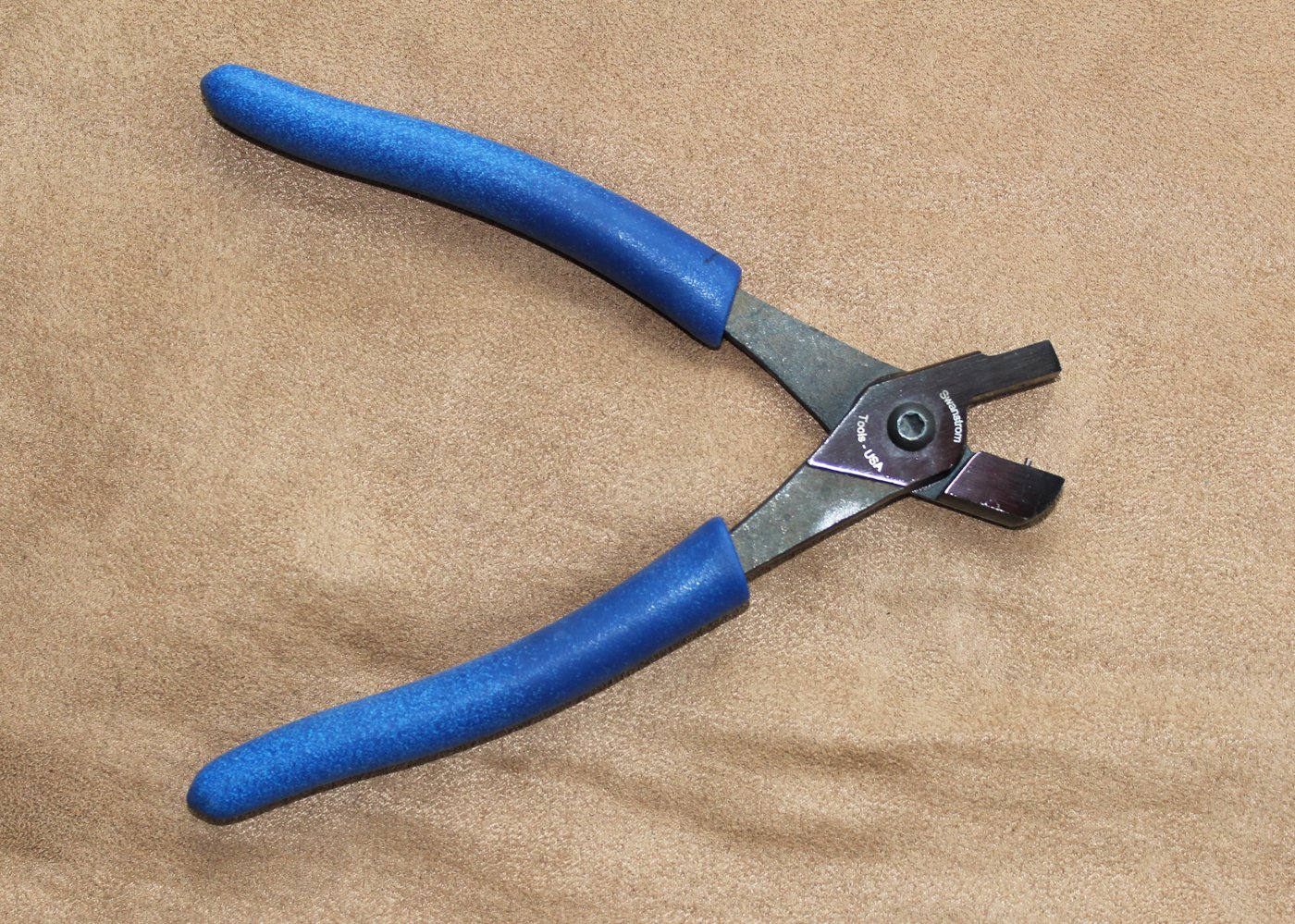
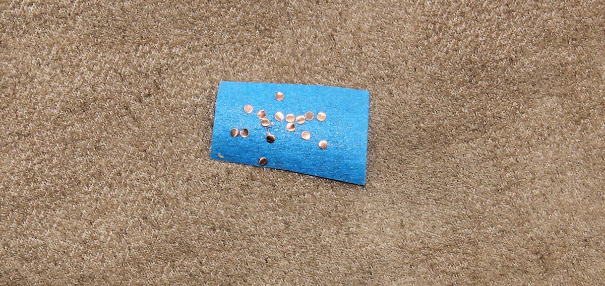
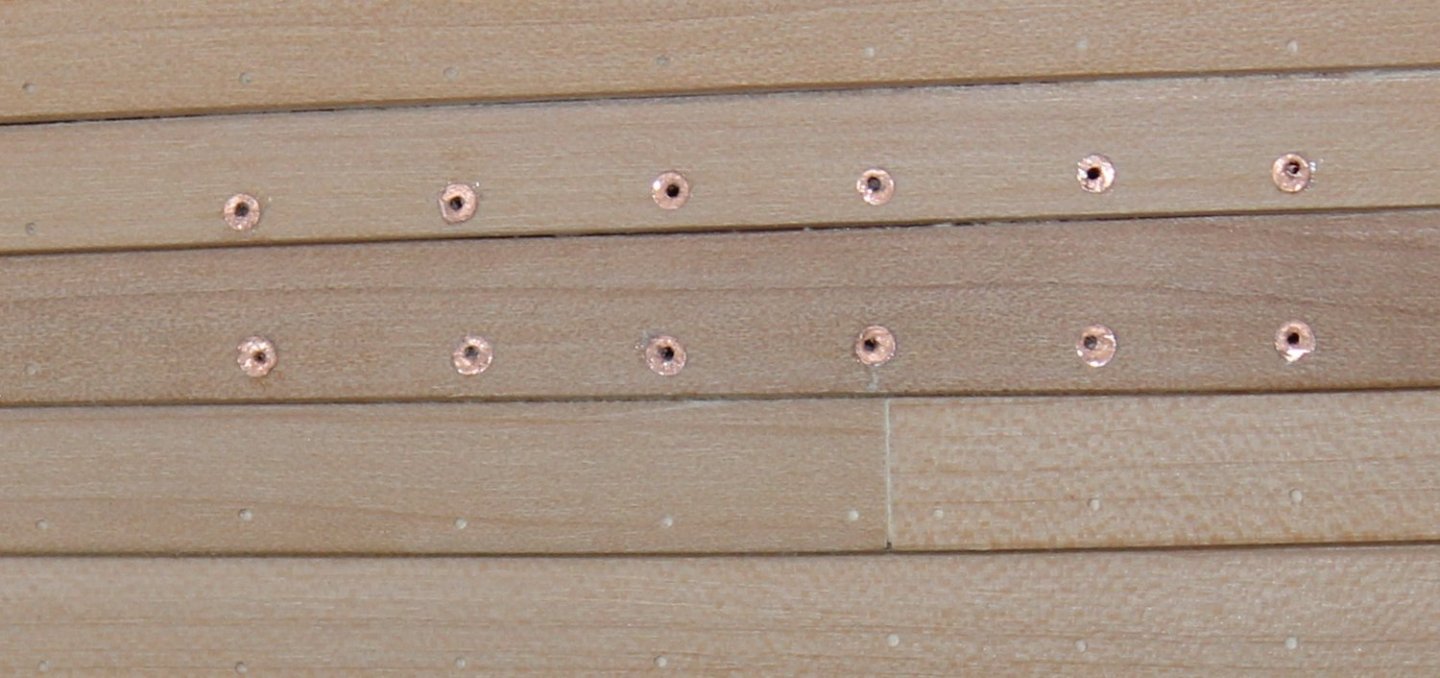
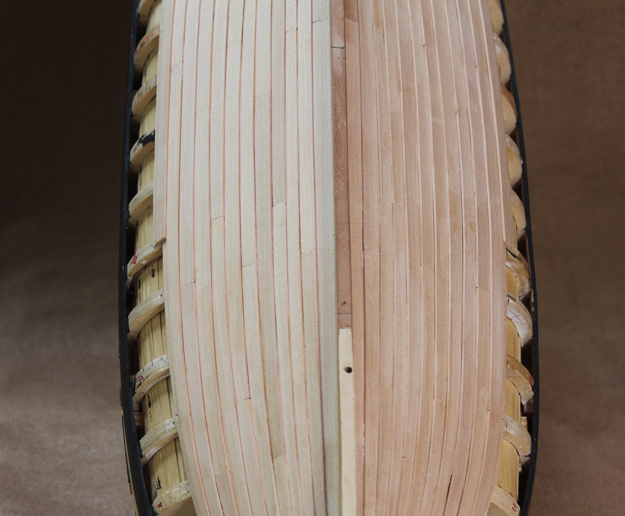
All of the holes for the bolts have been drilled. I then gave the hull a final sanding with 400 grit. Time to start the process of installing the bolts and roves. For anyone unfamiliar with the term, think of a rove as a washer, preventing the bolt head from digging into the planking. The process (so far) is as follows: 1. make the roves, 2. attach the roves, 3. sand the roves, 4. insert the bolts 5. file the bolts 6. go batty from doing this several thousand times. 1. I tried several different types and thickness of copper to make the roves, including self-adhesive copper designed for printed circuit boards. The self-adhesive copper worked perfectly until, on a trial piece, the adhesive failed with application of the finish. It might have worked with acrylic finish but I have never used one that I liked. So I decided upon 0.002" copper sheeting for the roves and 16 gauge copper wire for the bolts. This fits snugly in a #77 drill bit hole. All my holes were drilled with resharpened carbide drill bits. You need a steady hand because any twisting will cause them to break but they drill a consistently sized hole. I get mine at Drill Bit City. They run about $1 apiece. The roves are made with a 1.25 mm hole punched typically used in the jewelry industry. Mine were purchased at Rio Grande. https://www.riogrande.com/product/swanstrom-1-25mm-hole-punching-pliers/111785 2. I tried various adhesives to attach the roves. Medium viscosity CA worked the best for me. To prevent bleed onto the wood, I dip the back of the rove onto a drop of CA and then wick the excess off on a piece of paper before applying it onto the hull. Once they have dried, I pierce the rove for insertion of the bolt. 3. Next, I use 400 grit sandpaper to gently sand over the roves. This smooths out their appearance and lets me know which ones were not securely attached. The first picture is before sanding and the second is after. 4. I hardened the copper wire by stretching it and then inserted it into the hole. The fit is tight and only a few holes needed supplementary adhesive, in this case PVA glue. 5. Even though I used a side cutter, the end of the bolt needed to be filed flat. In the following picture, one can see all of the steps. From left to right, sanded roves, bolts, filed bolts and unsanded roves. The effect of filing is subtle in the photo but is more obvious in real life. 6. What you see here took three hours. So if you don't hear from me for the next month, you will know why.


- 277 replies
-
- 17
-

-
Swan-Class Sloop by Stuglo - FINISHED - 1:48
tlevine replied to stuglo's topic in - Build logs for subjects built 1751 - 1800
Sorry to hear about the accident, Stuglo. The idea of even owning a full sized table saw scares me. I also opted for a band saw to slice sheets off my billets. A lot of wood gets wasted because of the tooth marks but I still have all of my fingers. -
Thank you Christian. And thanks to everybody for the likes. Now is the tedius process of drilling the rest of the bolt holes and final sanding before starting the rove and bolt installation.
-
Greg, it took me a long time to bite the bullet and cut off the planking. But we are all a little bit crazy, aren't we... Druxey, if there is a next time, I will plan for the fashion piece from day one, not after most of the planking has been finished. The Hayling Hoy is the only one of David's books I don't own. Now I have a reason to complete my collection.
-
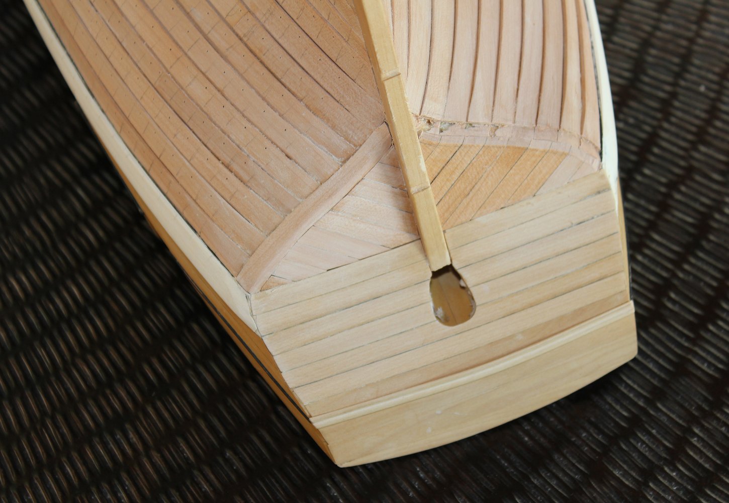
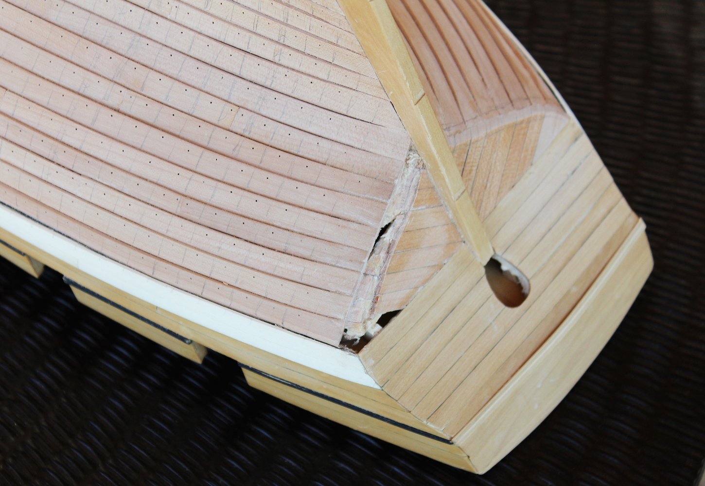
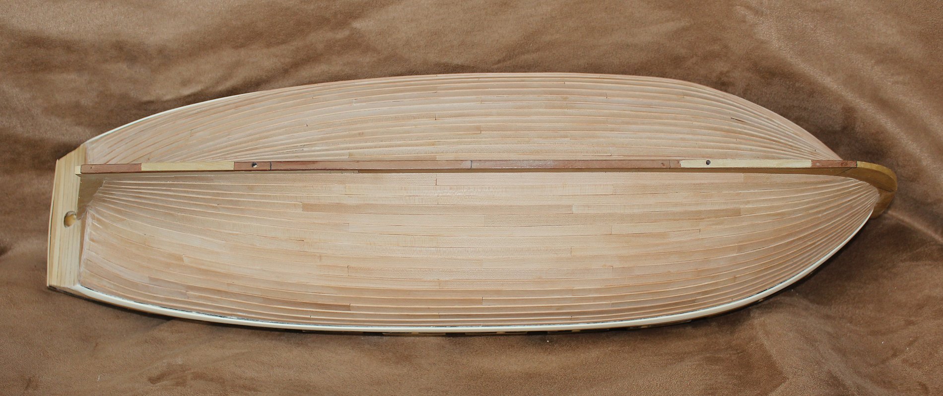
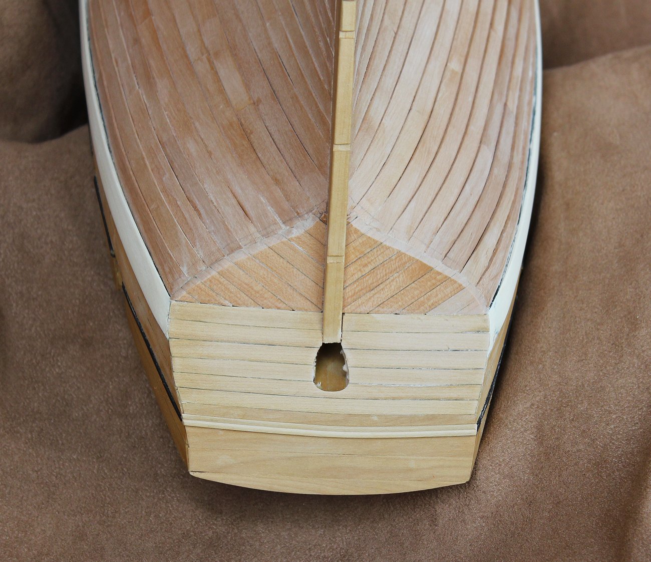
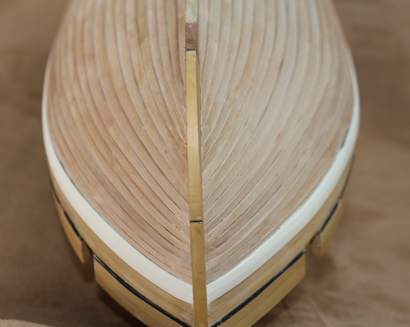
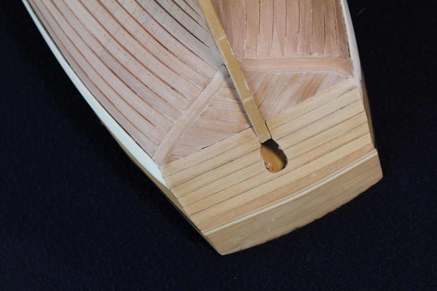
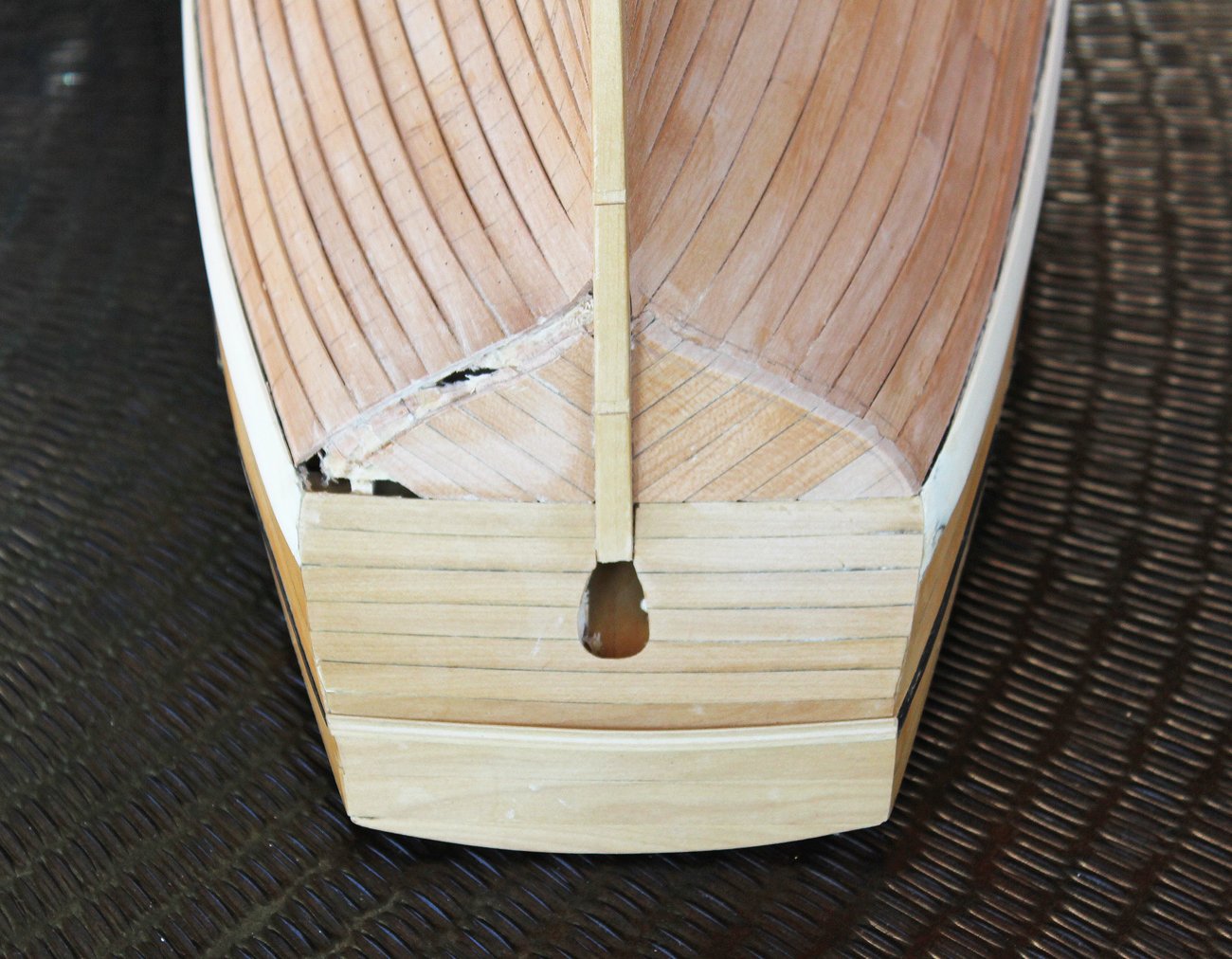
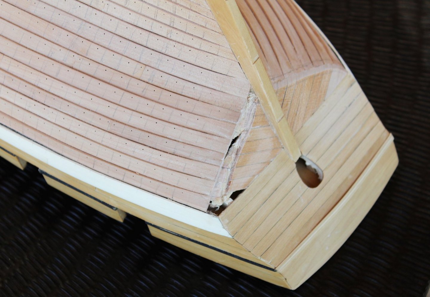
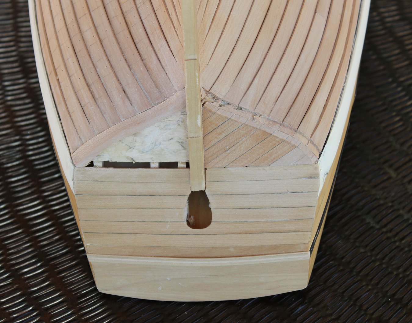
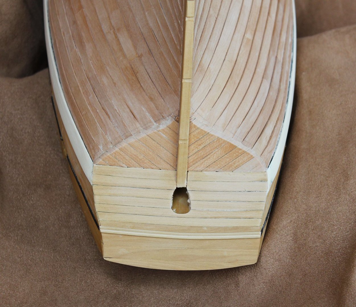
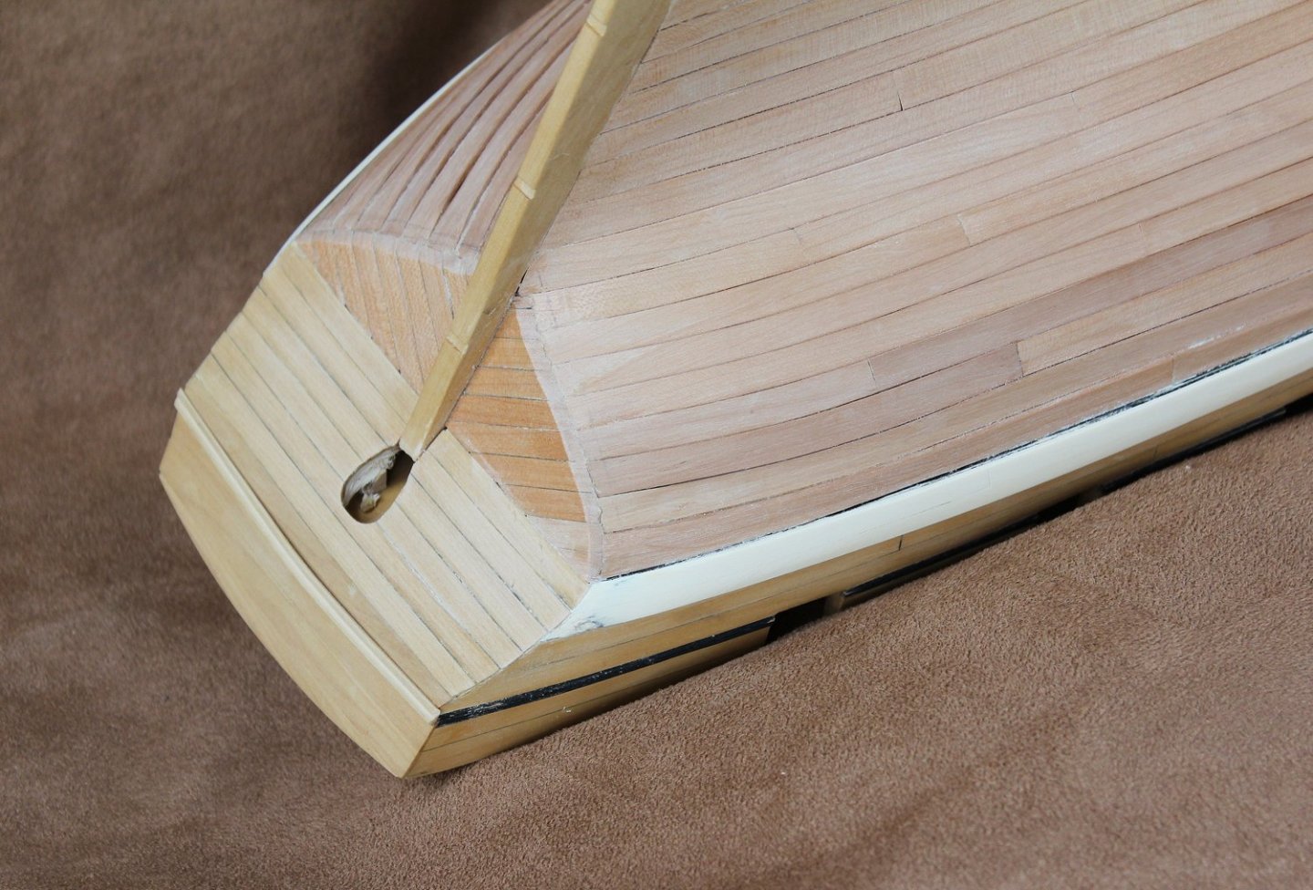
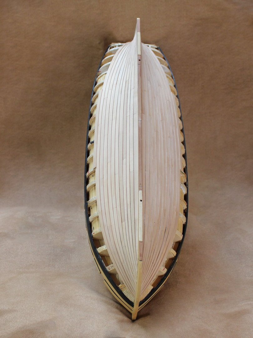
The fashion pieces are next. As mentioned in a previous post, I did not realize that the model would require them. I did not see any indication for them on the plan and the museum model was built without them. Having been shown the error of my reasoning... My construction technique would have been different. At a minimum, I would have made the aft bulhead double to allow for the cutback of the hull planking. The fashion piece is very difficult to fabricate because of the compound curves. Bending the wood with heat (both dry and wet) was unsuccessful. They were carved from a solid blank of pear. I drew the fore edge of the fashion piece onto the hull planking and using a chisel, removed the aft end of the planks. As alluded to above, the width of the fashion piece was limited by the need to provide support for the hull planking. In the pictures, you can see the amount of planking which was removed on the starboard side. Also visible are pencil lines indicating the hull frames and the #77 holes for the bolts. The transom planking was removed and new planks were installed after the fashion piece was in place. After I was satisfied with the appearance, I made the one for the port side. This entire process took approximately 20 hours. The final tapering of the hull planks into the fashion pieces will be done along the the final hull sanding after all the bolt holes have been drilled.

- 277 replies
-
- 20
-
-
Swan-Class Sloop by Stuglo - FINISHED - 1:48
tlevine replied to stuglo's topic in - Build logs for subjects built 1751 - 1800
I agree with Druxey and Greg...much better. If it is any consolation, this is one of the most difficult parts of the build. Oh wait, there are the head timbers, the stern framing, the carvings... Seriously, it will get easier as your skills improve. -
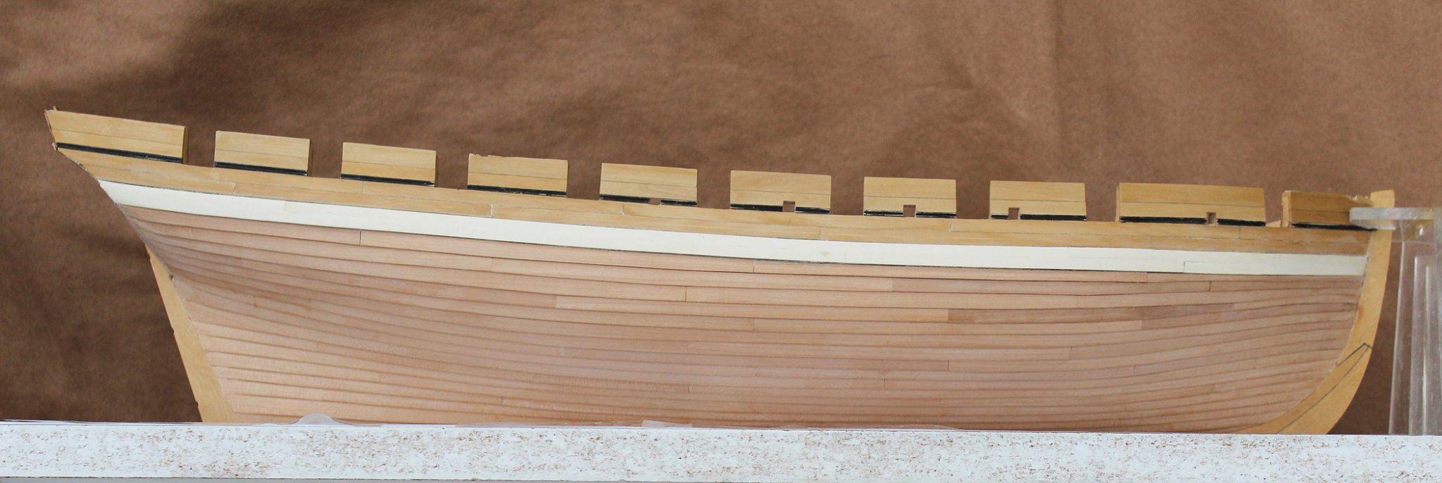
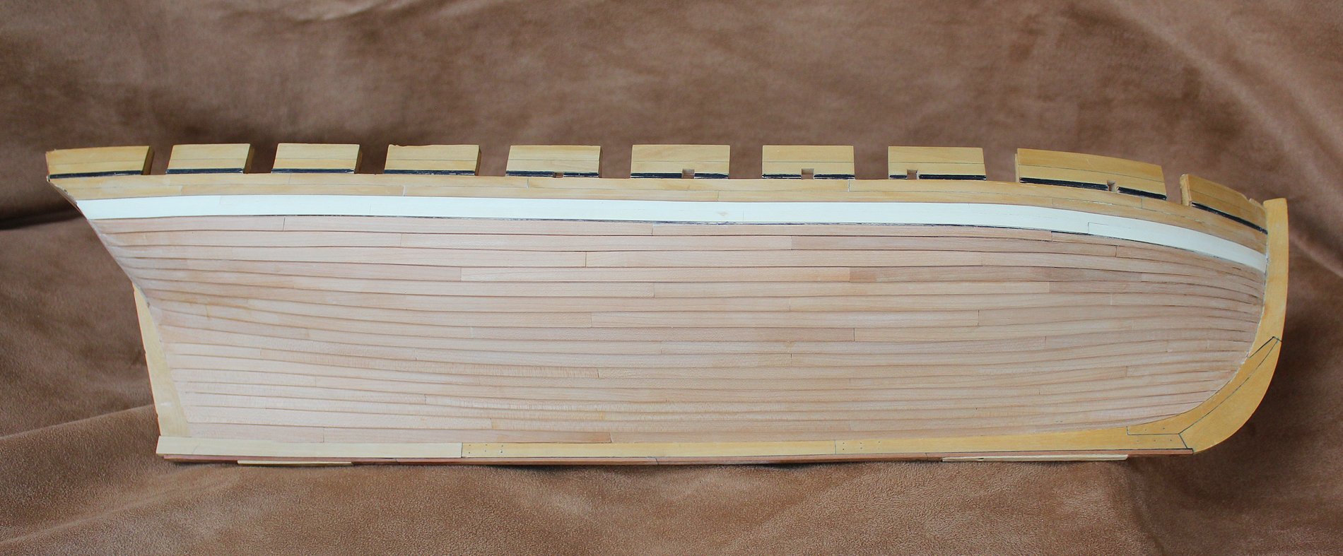
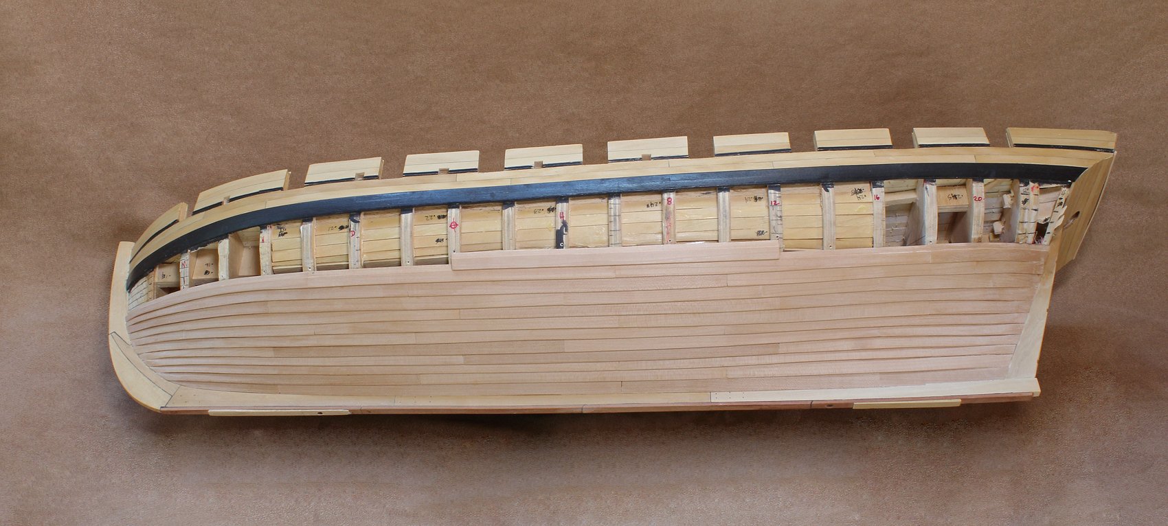
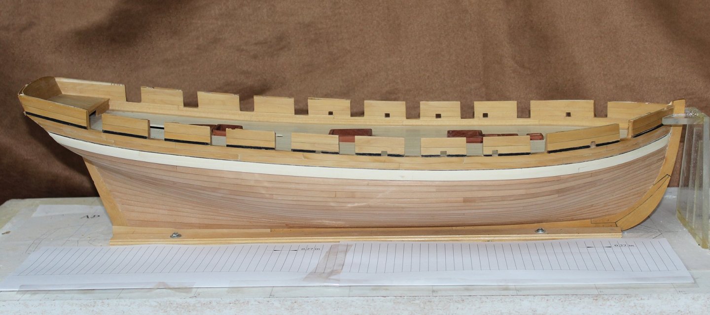
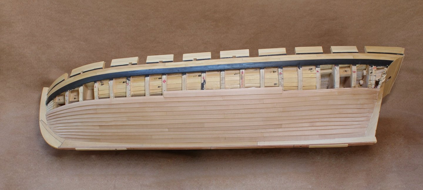
Roger, that is why I was hoping the adhesive-backed copper would have worked out. And it did until I applied the finish. As I mentioned yesterday, I have finished the hull planking. It still needs final sanding; that will occur after I have all the holes for the bolts drilled. The wale become rather the worse for wear over the last several months so I sanded it down and applied a veneer of holly. It will be painted with black artist acrylics after I have finished installing the bolts to prevent any further damage. I will also be replacing the decorative strip for the same reason. The pencil line at the stern represents the future location of the fashion piece, my next project. I have drawn up the locations of the bolts and secured it to the building board. These rows will be transferred to the hull and then the drilling will commence.


- 277 replies
-
- 17
-
-
Druxey, I am using a 1.3 mm jeweler's punch. Once I am satisfied with my technique, I will post details.
-
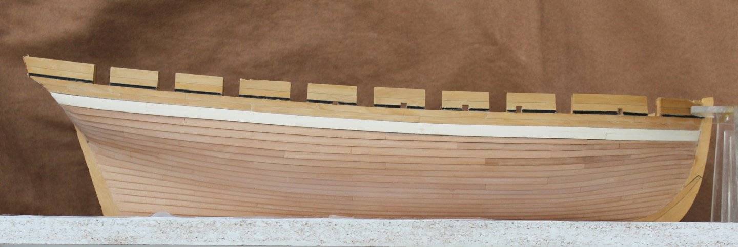
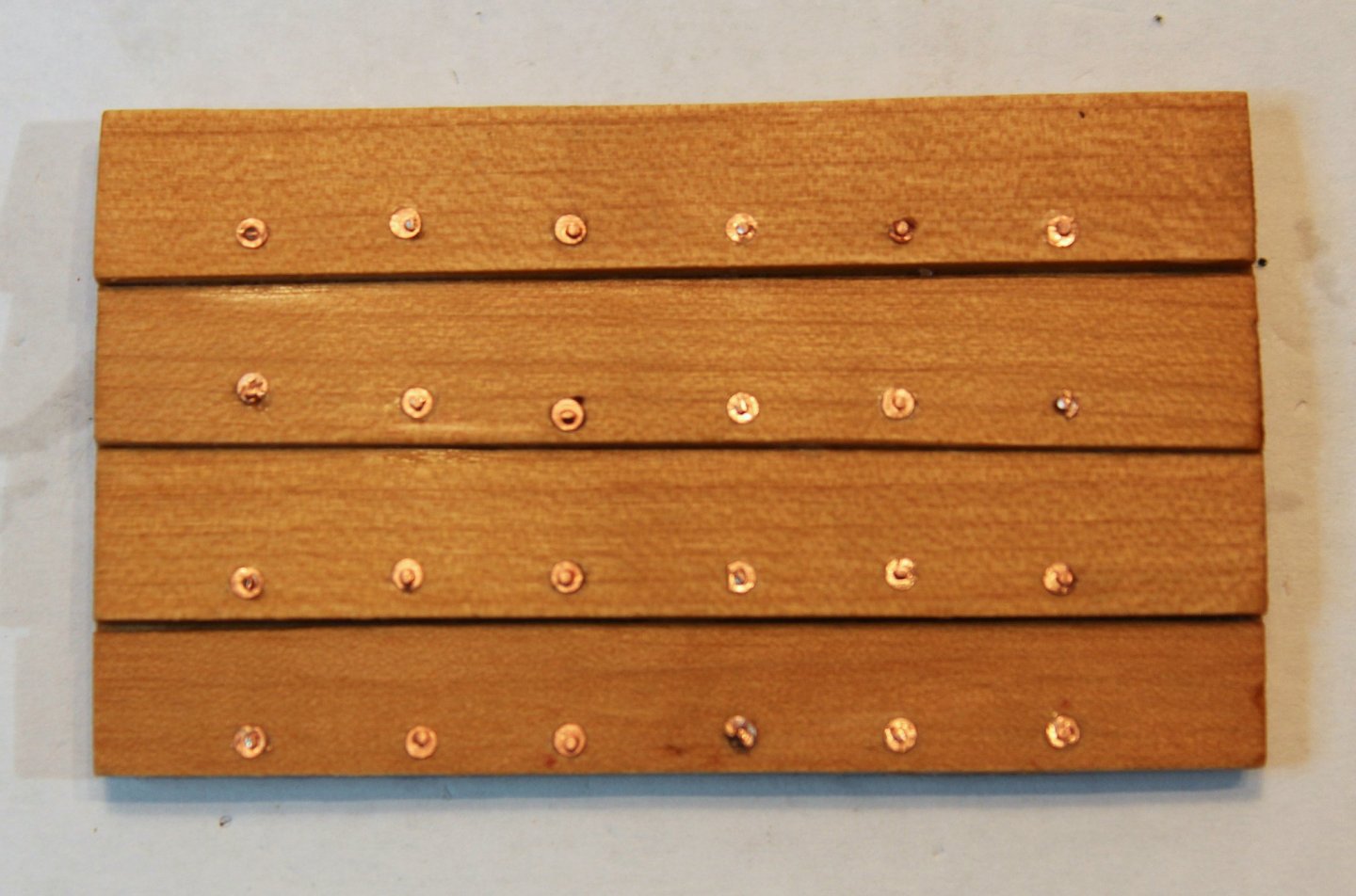
I have finally finished installing the planking. Hopefully, I will have pictures tomorrow. The planks are secured to the frames with roves (washers) and bolts. I was unable to find a framing diagram for a similar vessel and so do not know whether it was single framed or single/double framed. I have chosed single frames. Yedlinsky's book of scantlings states that for a cutter, the room and space is 26", the floor timber is 9 3/4" wide and the first futtock is 10 1/2" wide. This would leave distances between the column of bolts of 13 1/8" and 12 7/8". At 1:48 scale, the difference is negligible so all my bolts columns will be 13" apart. I wanted to show both the roves and bolts. After a lot of experimentation, I have decided on the pattern seen in the left-hand three rows. On the left, the roves are punched out from copper sheet, applied with CA. On the right, the roves are punched out from copper tape. The adhesive was not strong enough to hold the copper on the plank without the addition of CA. I also tried using epoxy, Duco cement, yellow glue and contact cement but the CA worked best.
- 277 replies
-
- 14
-
-
what is the best hand plank crimper
tlevine replied to ronald305's topic in Modeling tools and Workshop Equipment
But DA talks about using a thicker piece of wood and carving it to the correct shape. This is what I typically do. With a little bit of patience and the correct mandrel, you can bend any stripwood into a right angle. -
The domain name has expired for Ship Ahoy. I also have the replacement motor for the Preac and love it.
-
what is the best hand plank crimper
tlevine replied to ronald305's topic in Modeling tools and Workshop Equipment
Try this... Find something that has the approximate curvature you are trying to achieve. Pots are very good for this. Assume you are going to have to trim the end of the plank so cut your plank longer than necessary. Moisten (do not soak) the plank and clamp it to the rim of the pot. Hold the free end of the plank in one hand and use a hair dryer on high heat to blow hot air onto the plank. Warm the entire plank and then concentrate on the area you want to bend. Gently bend the plank around the pot until you get the curve you need. -
There is also a lot of misinformation about true silver soldering. For example, the mating surfaces need to be clean but they do not need to sit in vinegar or pickle prior to soldering. What they need is perfect contact. Silver solder will not fill in a gap. In a lot of situations, it is better to gradually heat the entire piece rather than concentrating on the solder site. This will help prevent the solder chip from flying. Try laying the silver chip under the piece instead of on top.
-
Levmiller, you still have healthy ash trees? Around Chicago, the emerald ash borer has killed off 99.9% of them. I still have two trees but that is only because they get a very expensive treatment twice a year. And if you live in an area where the ash borer has been found, all ash wood needs to be removed by someone who knows how to dispose of the wood properly. For that reason, I would not recommend it.
- 28 replies
-
- 1
-
-
- construction
- models
- (and 3 more)
-
2021 NRG/MSW Calendar
tlevine replied to tlevine's topic in NAUTICAL RESEARCH GUILD - News & Information
These are the links to the models featured in the calendar. Bob's fishing pink and Gus' Sussex are unpublished. The other models can be found in various issues of the Nautical Research Journal. -
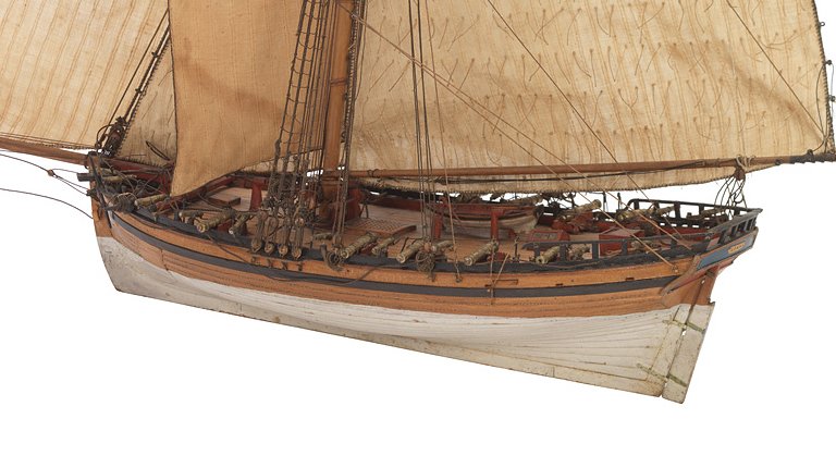
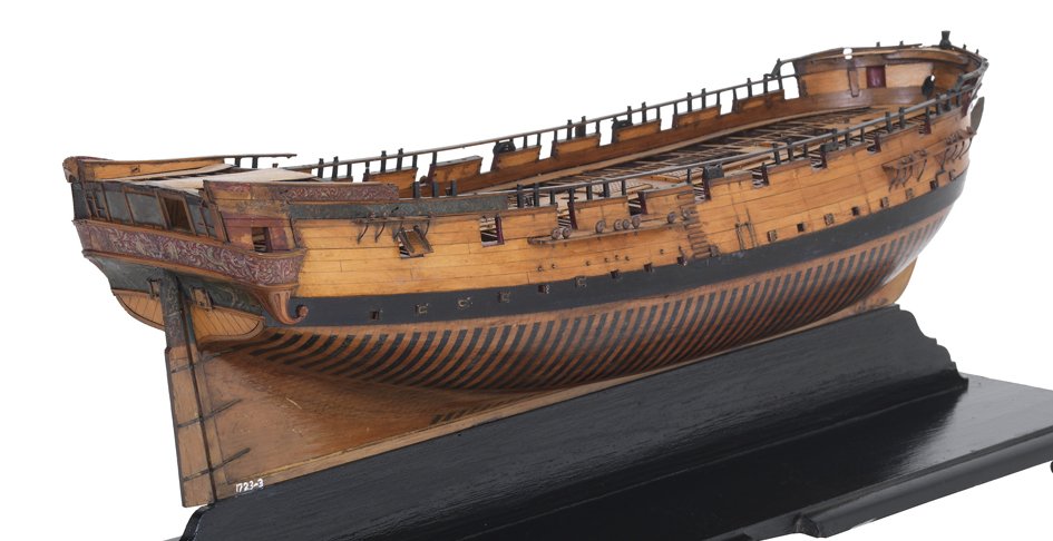
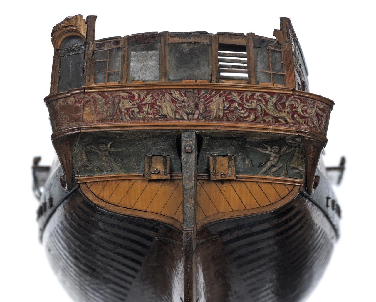
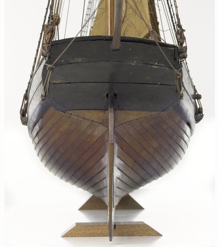
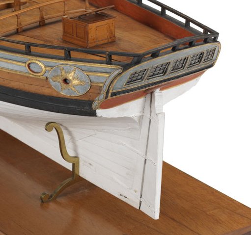
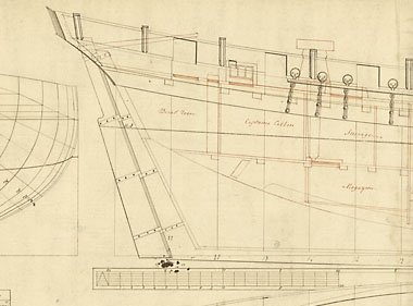
To make things more confusing, let me share the sterns of a few other models from the RMG. The cutter Hawke (1777) and the Trinity House hoy (c.1800) were clinker built. I do not see a fashion piece extending onto the transom on either model. Lowestoft (1723) is earlier and larger (sloop of 20 guns) but nicely demonstrates a square stern with a fashion piece extending to the bottom of the transom. Finally, the French lugger of uncertain vintage clearly shows that the hull planking covers the open grain of the transom planks but there is no fashion piece. Hawke Hoy Lowestoft Lugger
-
If I carried the lapstrake all the way to the transom, such that there would be a saw-toothed appearance, that would be erose. Sorry about the obscure verbiage. As druxey states above, "...make gains until the planks are flush with each other into the rabbet." So my question was whether the planks should be flush with each other at the transom as well. druxey, the model does not show a fashion piece below the wale, which I found odd. I also thought the rectangular piece at the stern represented the transom, rather than a fashion piece.
-
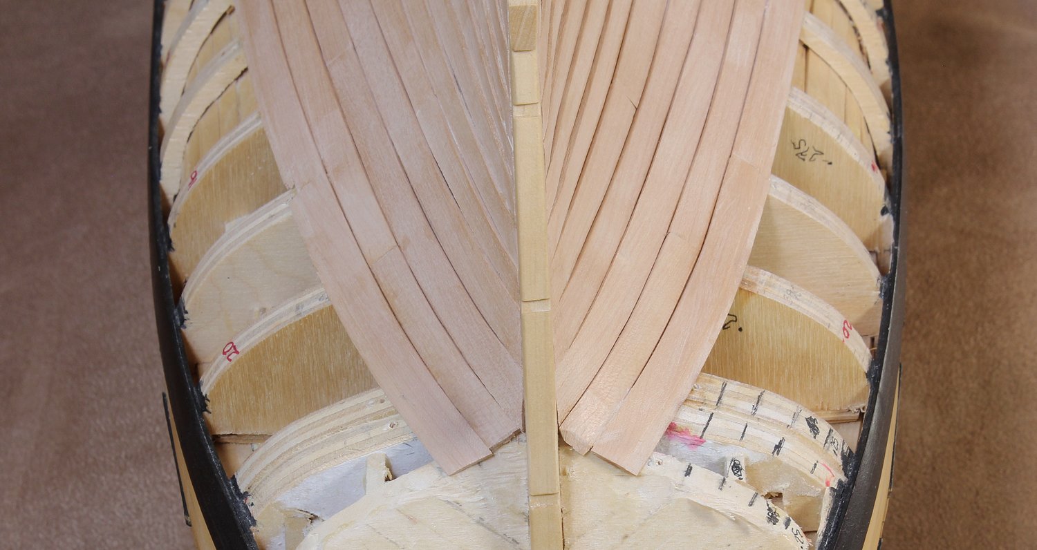
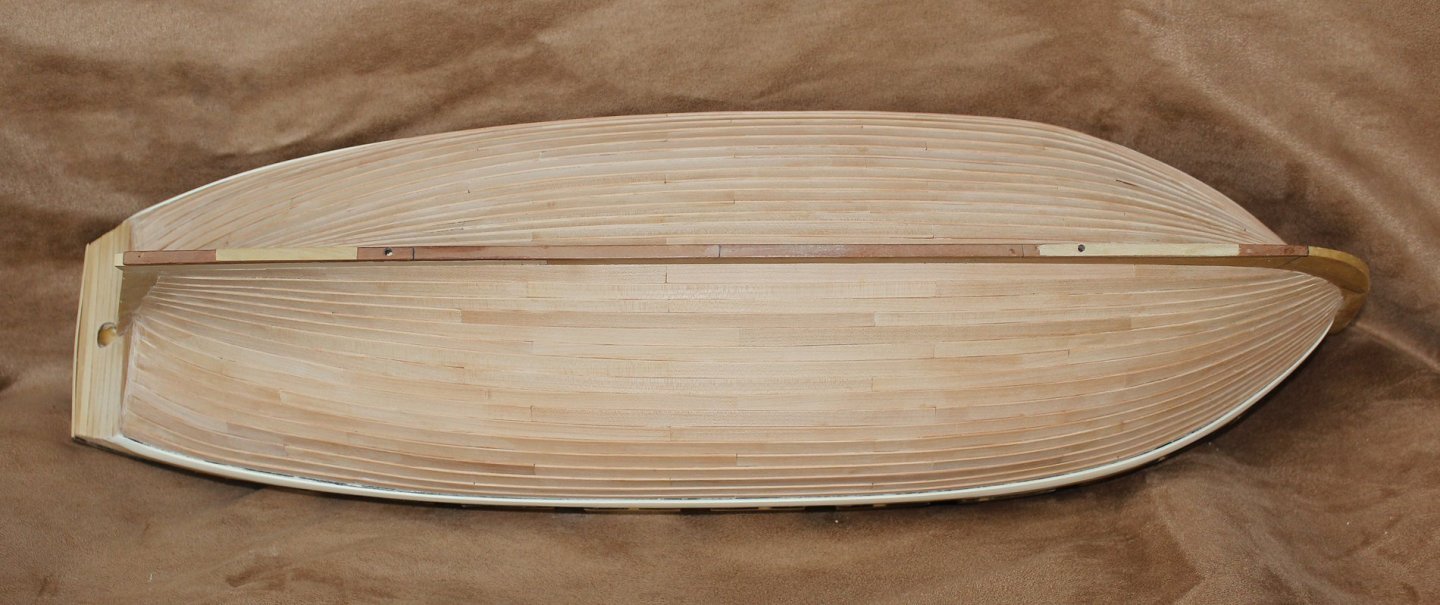
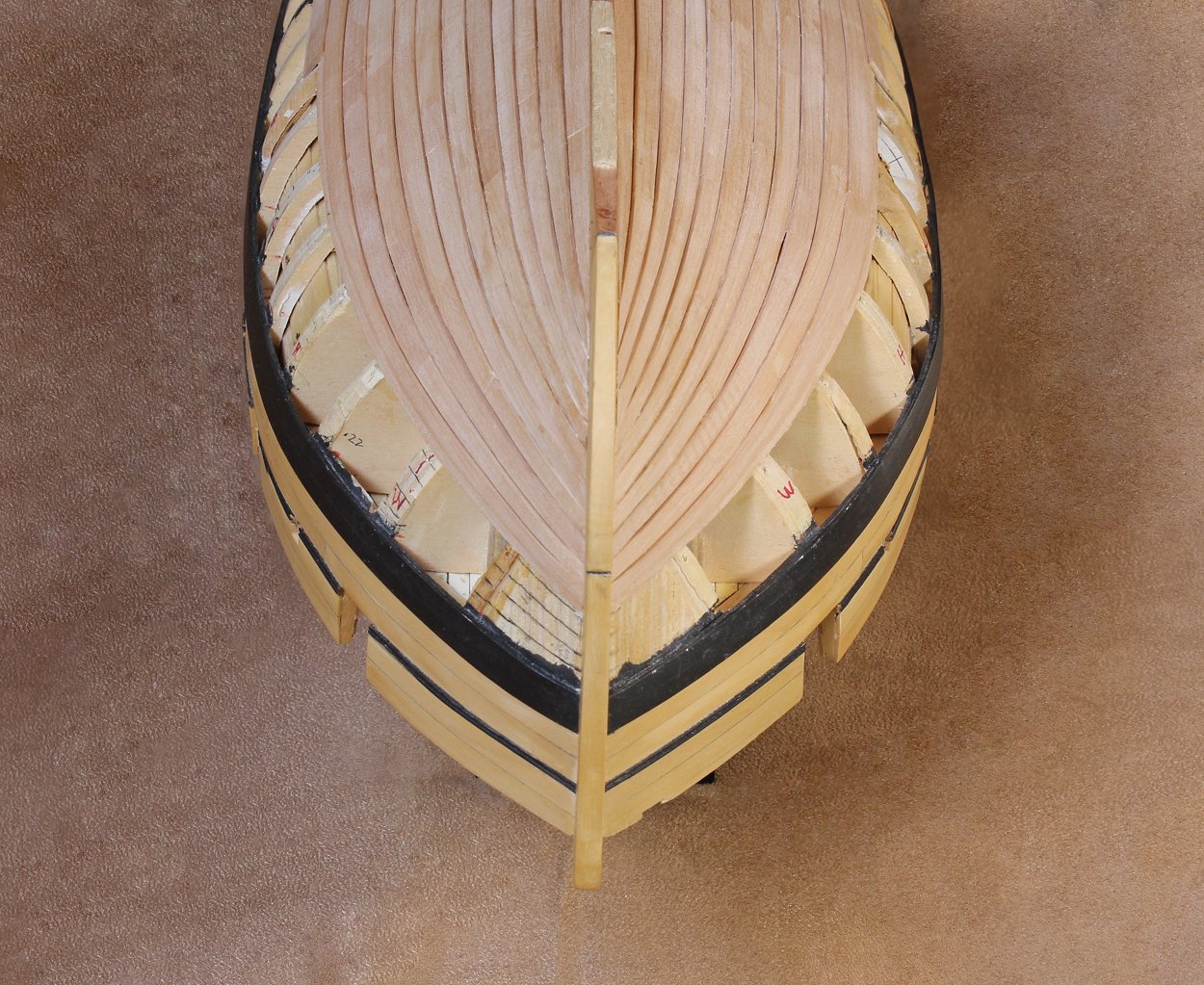
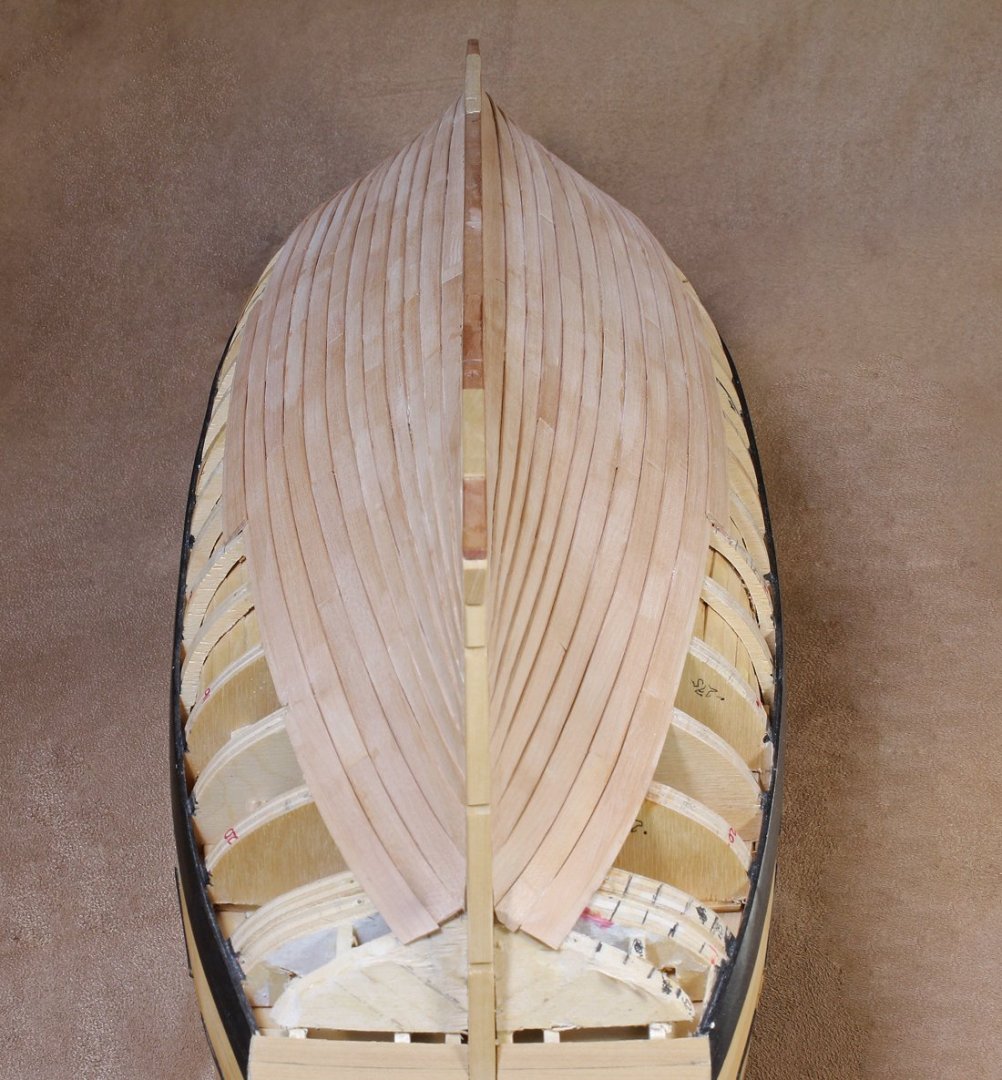
Finally, the second planking belt is completed. My biggest decision was whether to have the aft planking feather out at the transom or leave it erose. I saw examples from this era using both approaches and could not make out the detail on the model. I decided to continue to feather the planks. Those of you who are wiser than I, please correct me if I am wrong, as it would not take too much work to go the other route. I removed the transom planking and will re-plank it after the hull planking is completed. Only six more rows to go!

- 277 replies
-
- 22
-
-
The NRG is pleased to announce that we will be offering a calendar for 2021. These pictures represent some of the best models being produced by members of the Guild and MSW. Some of these pictures have never been published. AVAILABLE FROM THE NRG STORE


- 11 replies
-
- 12
-