


fake johnbull
-
Posts
128 -
Joined
-
Last visited
Content Type
Profiles
Forums
Gallery
Events
Posts posted by fake johnbull
-
-
Daniel,
Thank you for your comment and sorry for not updating my building log.
Although I don't have enough time to write English text at this moment, I have been posting latest status of my building to Twitter with Japanese text. So appreciated if you are enjoying them till I add new post to this topic.
https://twitter.com/fake_johnbull/status/1386226116659007489
I have almost finished upperdeck arming and fittings.


-
Improving of head rails and cathead support
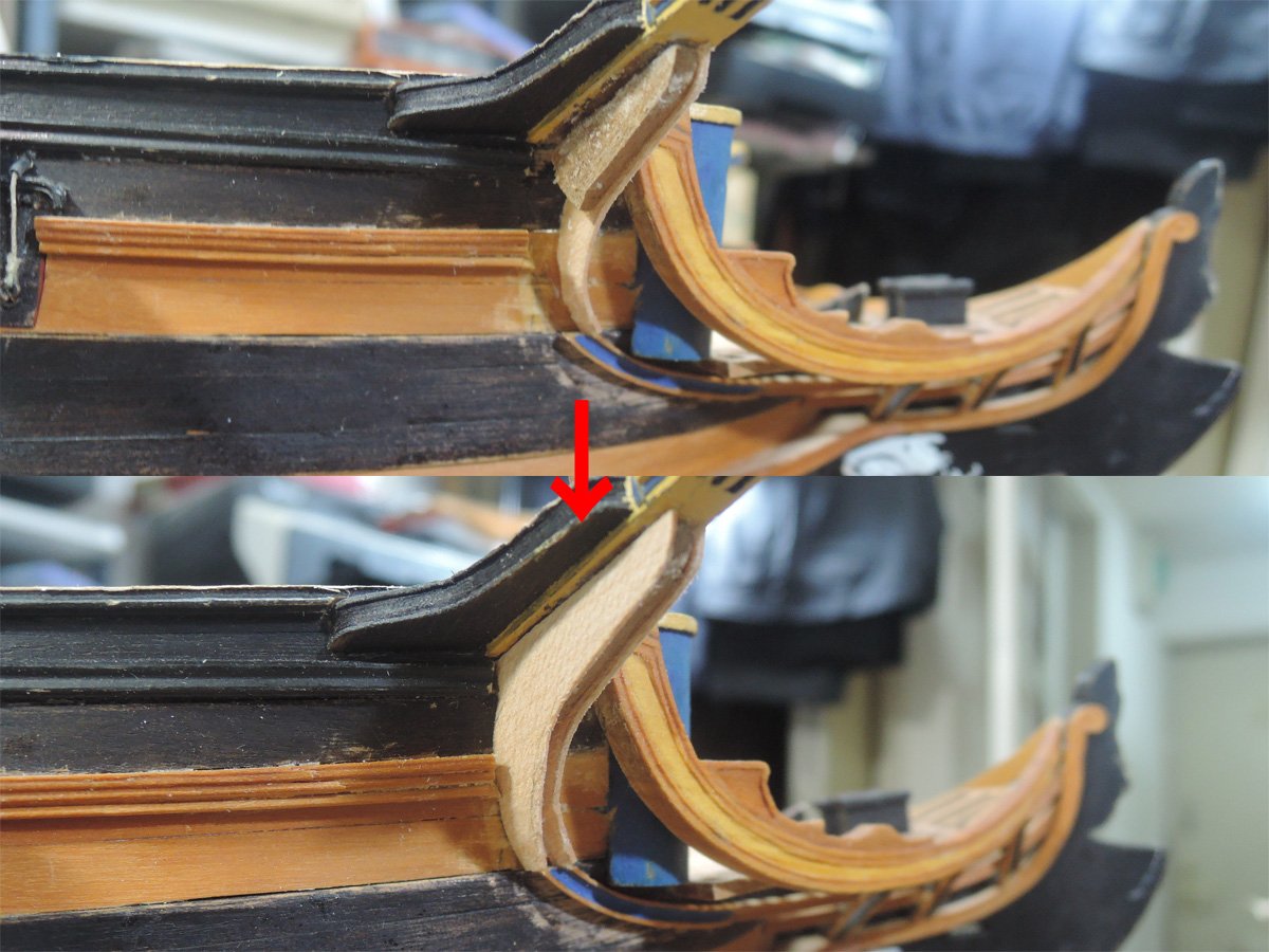
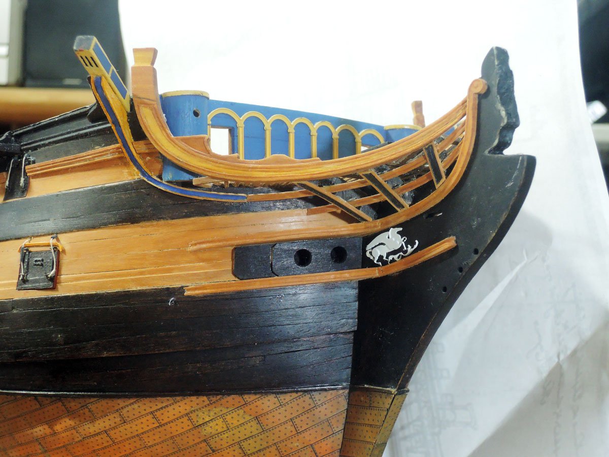
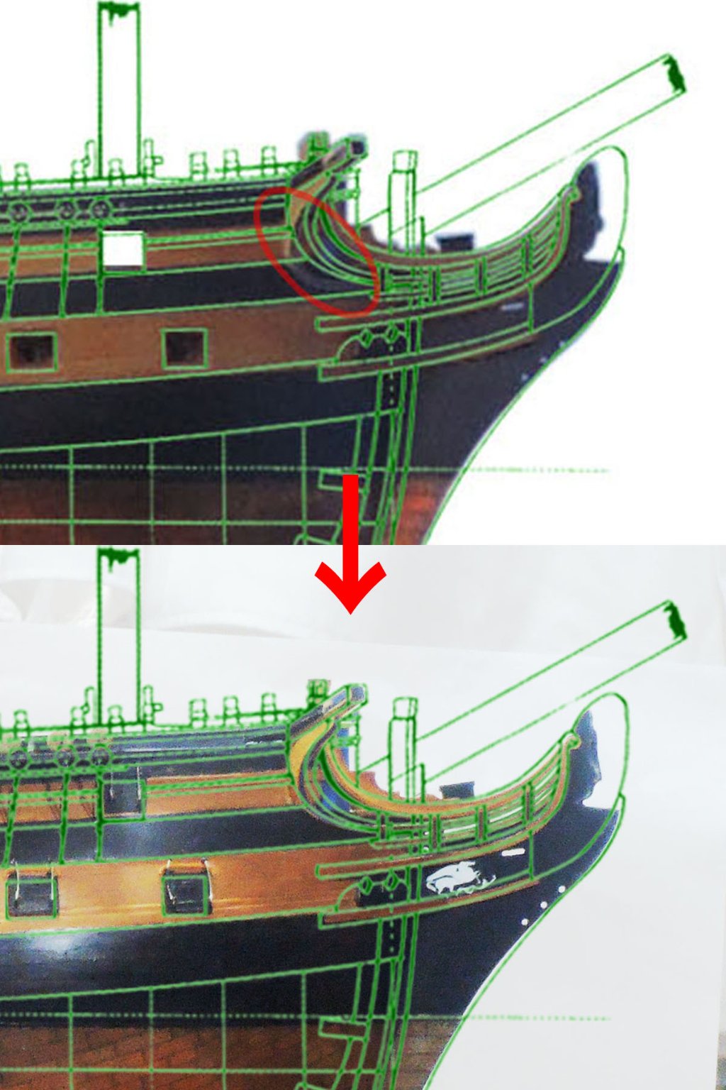
Before finishing rest of external hull details, I tried remaking of head rails and cathead support. When I firstly finished these areas, I was satisfied with the result.
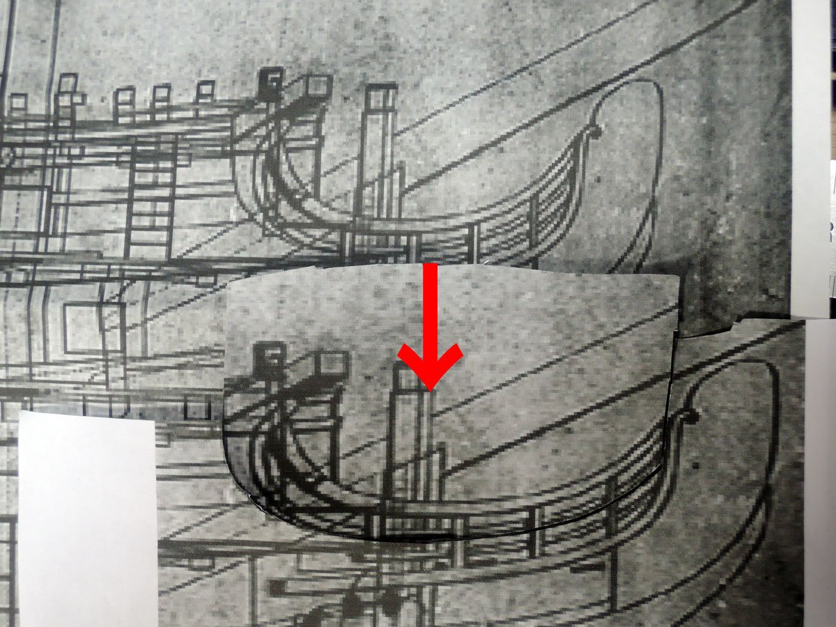
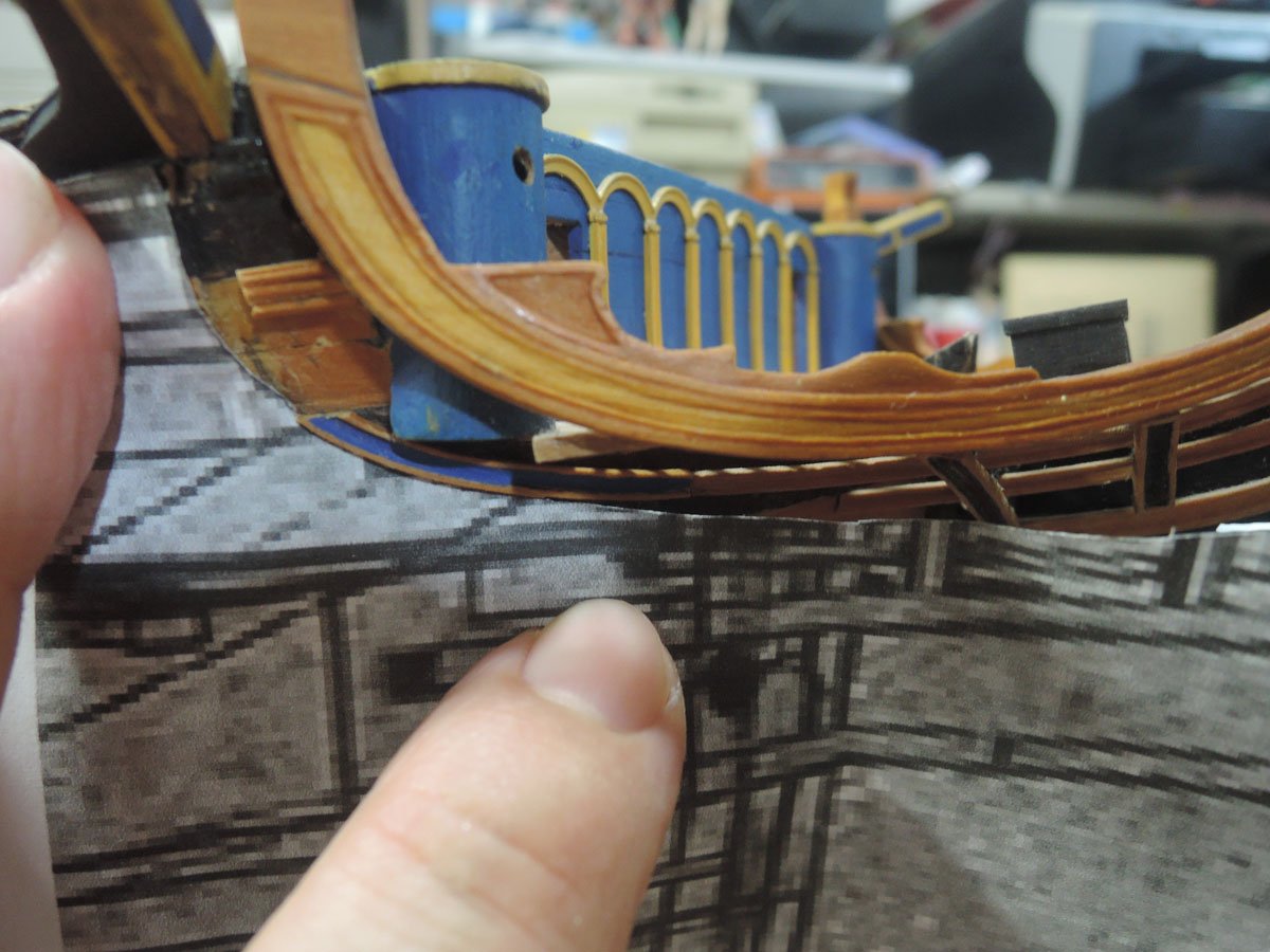
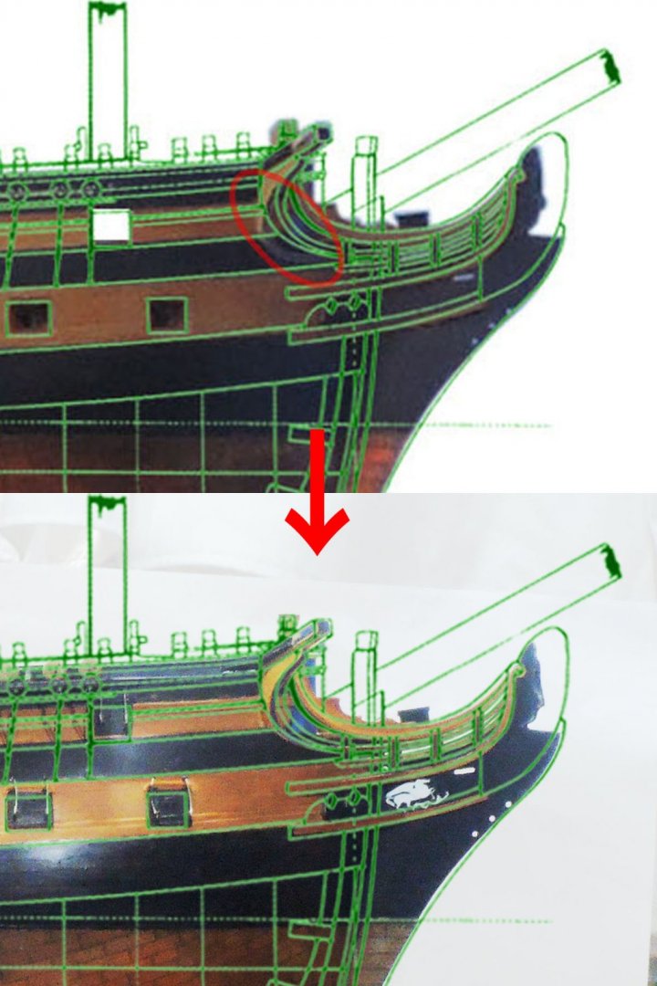
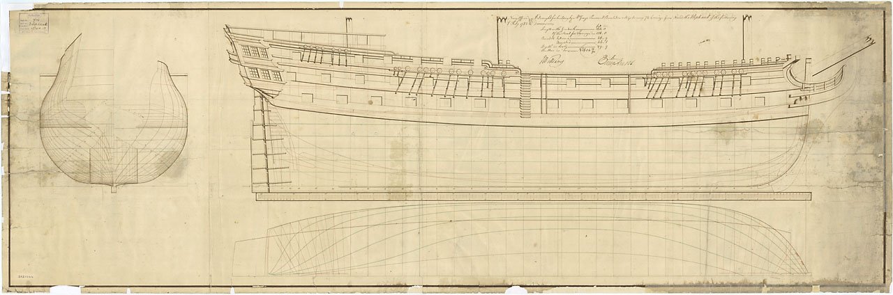
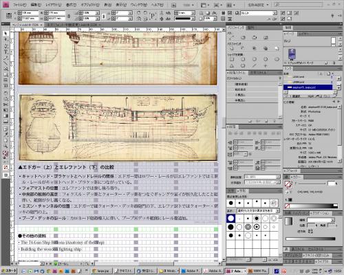
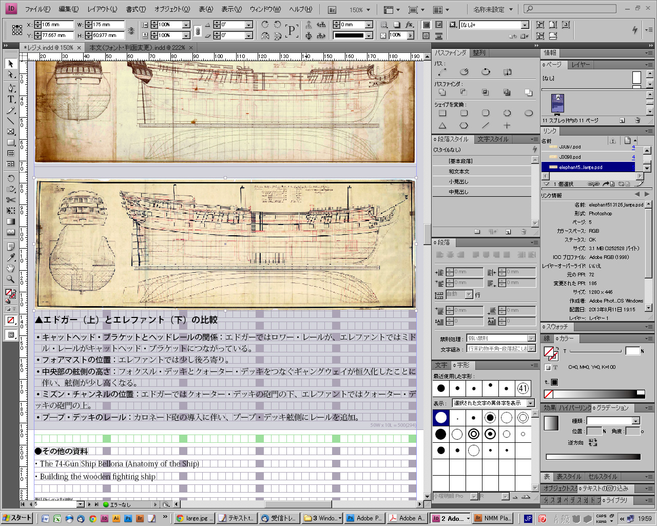
But later it became apparent that the curve of cathead support and ekeing rail is too acute than it should be by comparing my model with plan of Elephant. Elephant plas is shown in green line. Also mould on main head rail is simpler comparing with many beautiful models of past days.
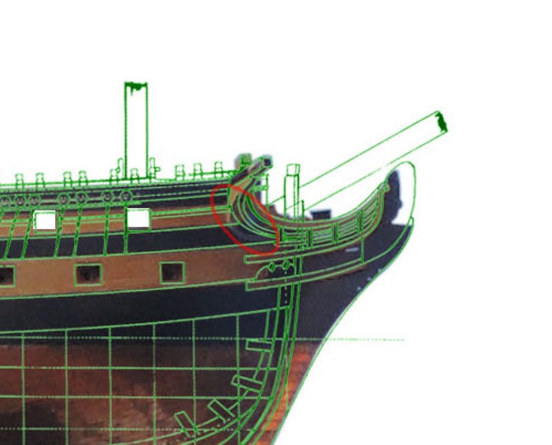
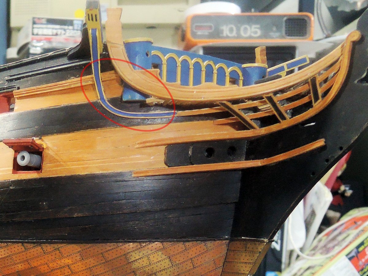
These parts are one of most difficult items to form, so I have been reluctant to rework them. But I finally determined to do them before proceeding further steps. BTW, I don’t know exact place where cathead support and ekeing jointing together, but for convenience, I divide them at top edge of channel wale. I would call part running between top edge of channel wale and cathead “cathead support”, and curved rail connecting cathead support and head rail “ekeing”. My apology if my usage of term is incorrect.
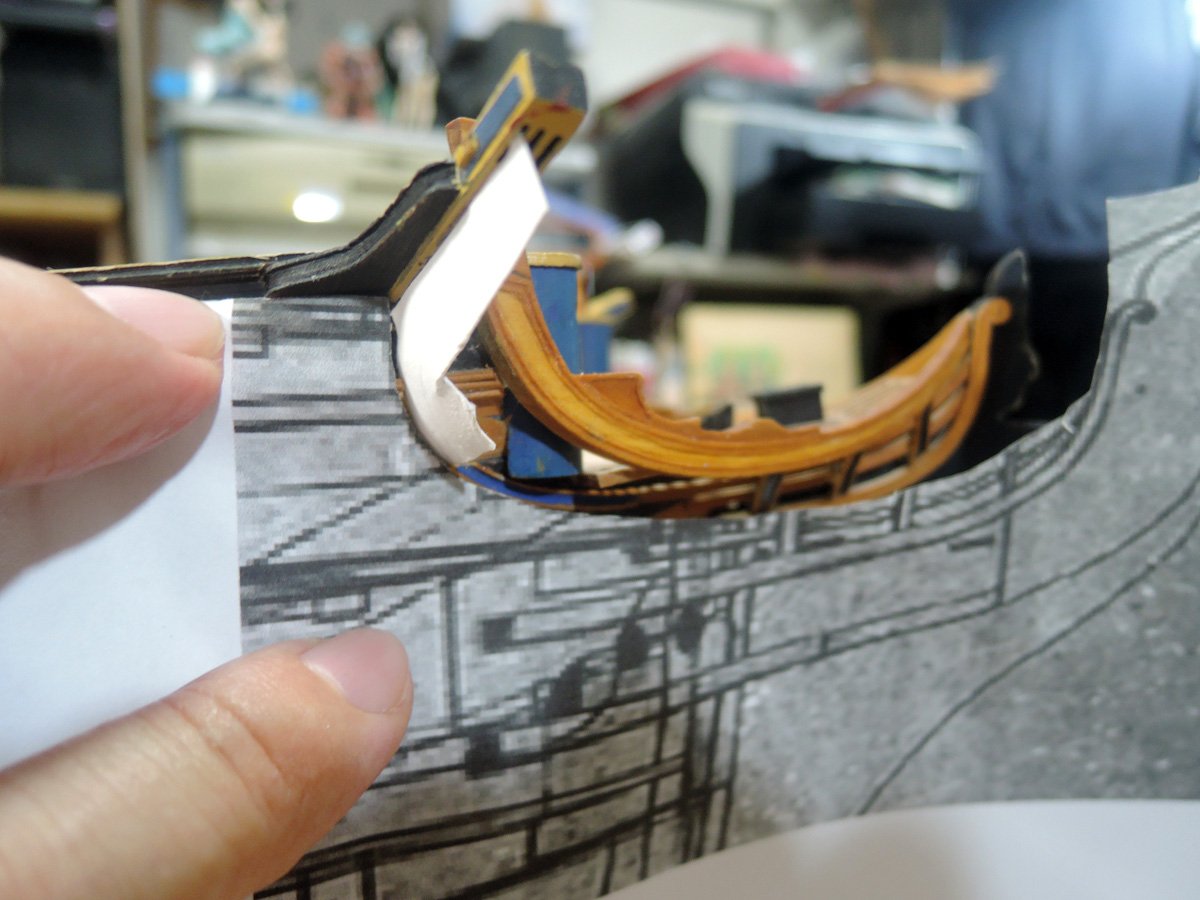
I firstly prepared NMM Elephant plan and expanded its bow section horizontally so that distance between forepeak of middle head rail and cathead support matches to actual length. Then cut it at bottom edge of middle head rail to use it as template.
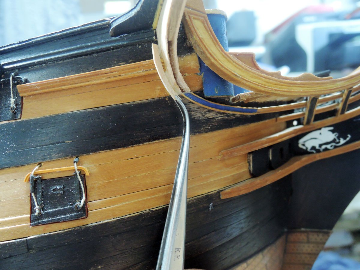
Next I remove old cathead support and ekeing. Old ekeing part are modified to gentler curve than before, and fitted to channel wale with help of template.
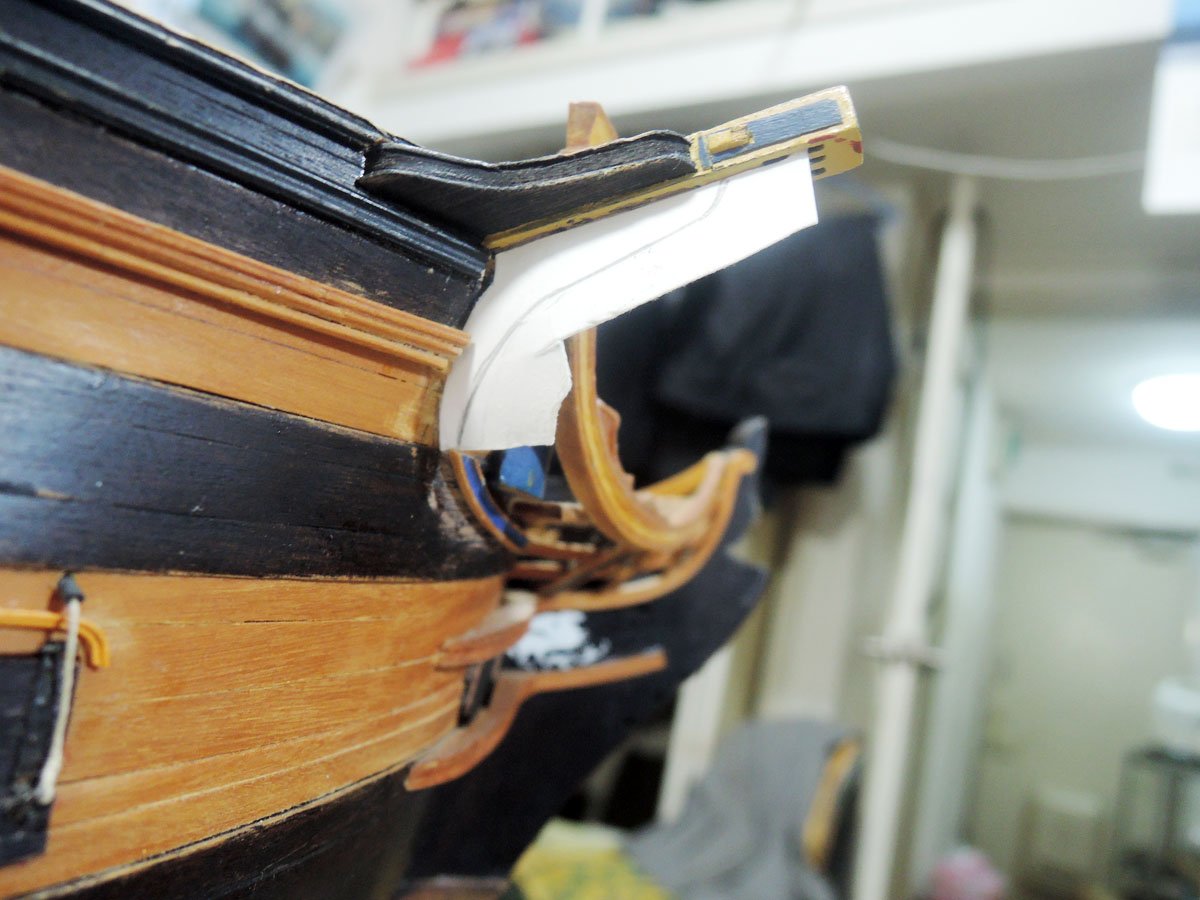
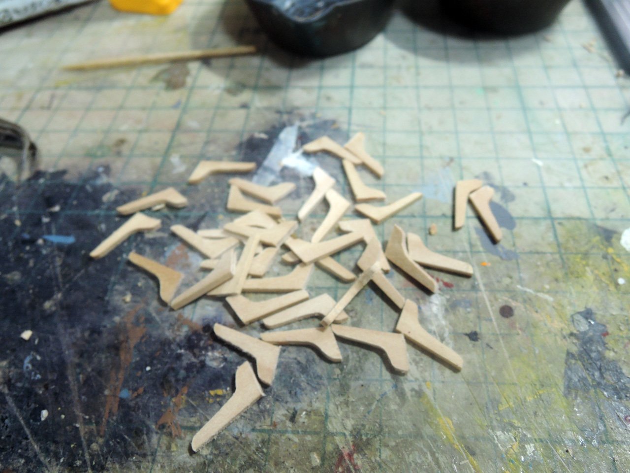
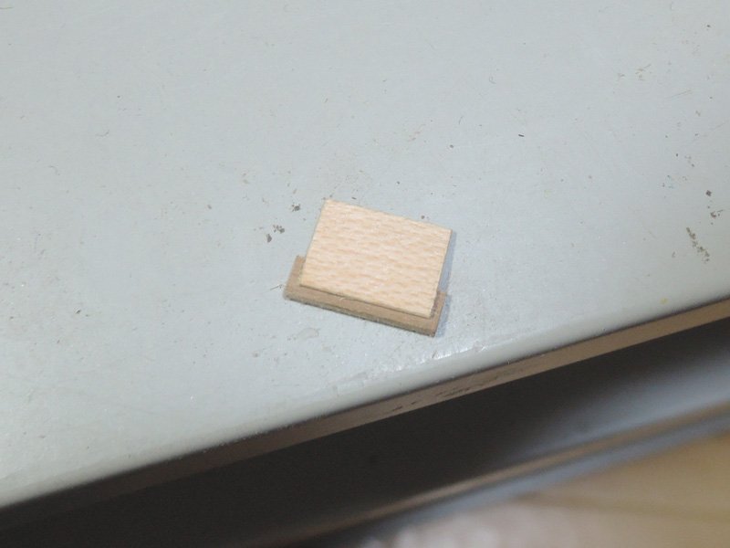
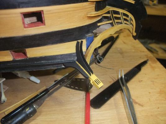
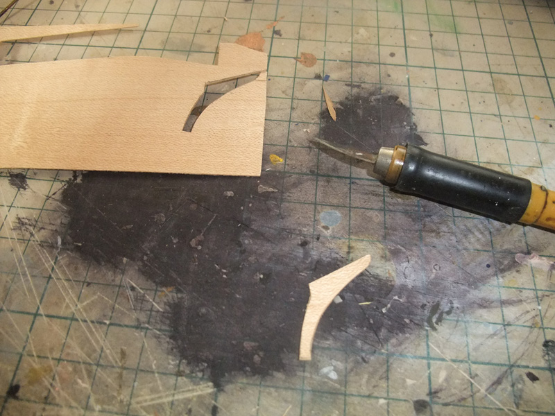
Cathead support is completely new one. I prepared pattern cut from Bristol board and test fit it to hull with help of Elephant plan template. Once satisfied with the shape of pattern, I transferred outline to 0.5 mm maple sheet and cut them. They form forward and rearward faces of cathead support and need two parts per one cathead.
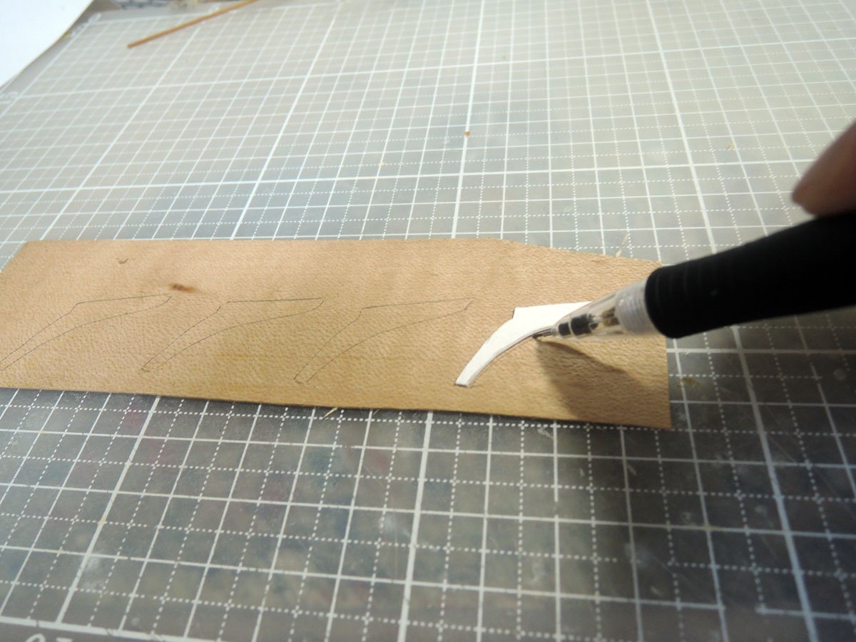
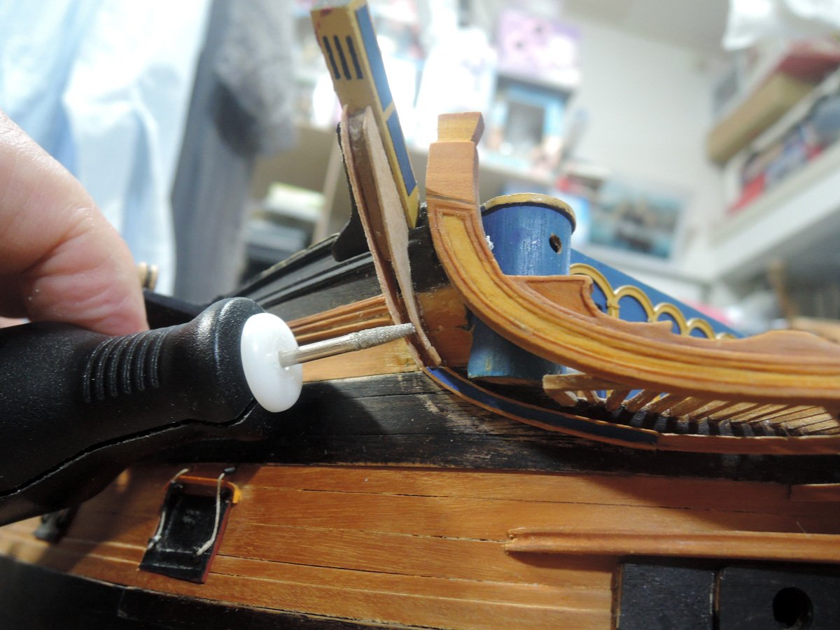
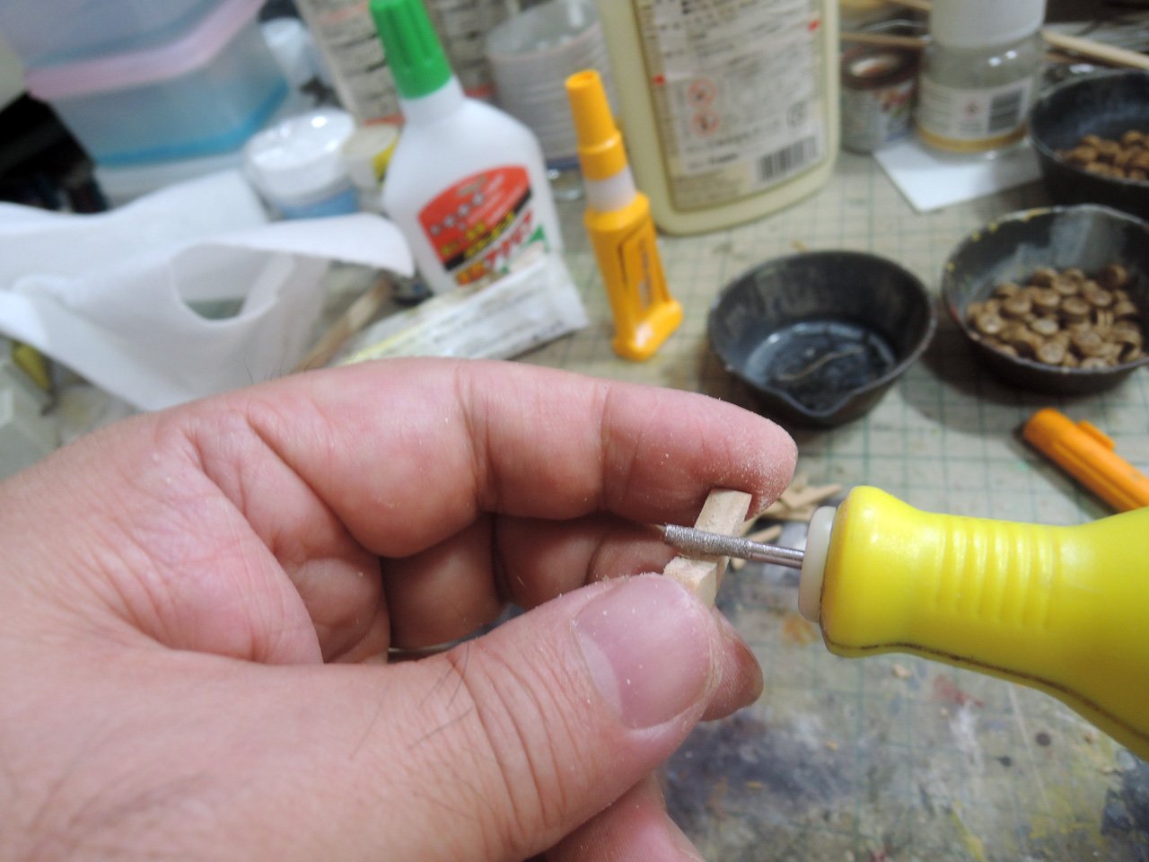
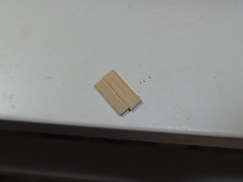
2 mm walnut strip is cut to fill horizontal arm of cathead support between forward and rearward faces. It is cut slightly smaller than maple part to represent mould of cathead support. BTW cathead is projectiling diagonally forward. As a result each length of forward and rearward faces of cathead is different. When I made cathead support previously, I prepared patterns for each of forward and rearward faces because forward one is little smaller than the other to correspond this difference of length . But this time I prepared only one pattern and cut rearward one slightly larger and shaped both of forward and rearward ones at once with small electric router after fitted to hull.
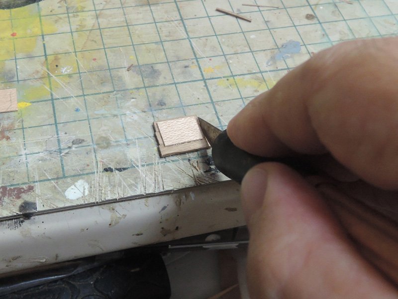
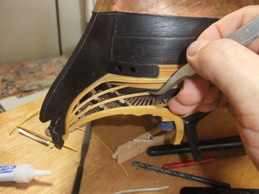
Rest of void between forward and rearward faces are filled with 0.5 mm maple sheet cut into arc.
Yellow area is finished with yellow dye and Watco oil of natural colour. Blue area is painted with Humbrol No. 25.
Also more moulds are added to main rail.
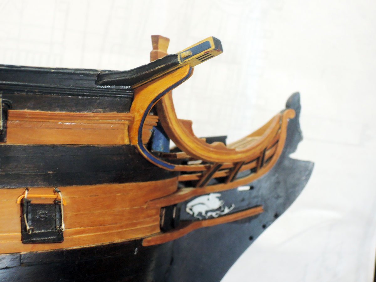
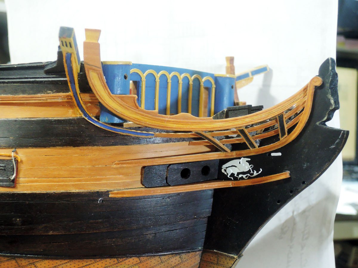
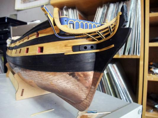
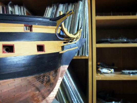
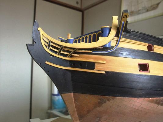
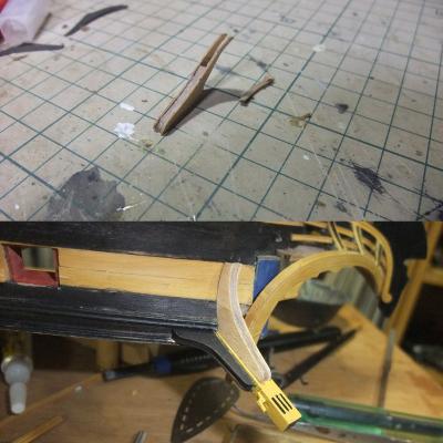
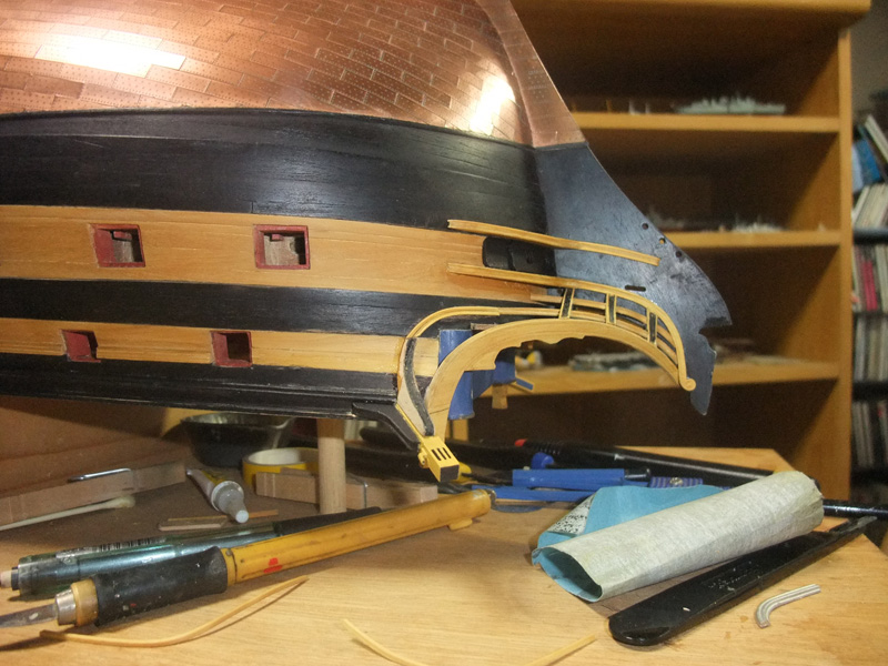
Reworked cathead support and ekeing is still slightly out of Elephant plan, but I’m satisfied as a whole. It looks much preferable than before.
-
Jason,
Thank you for your kind word😄
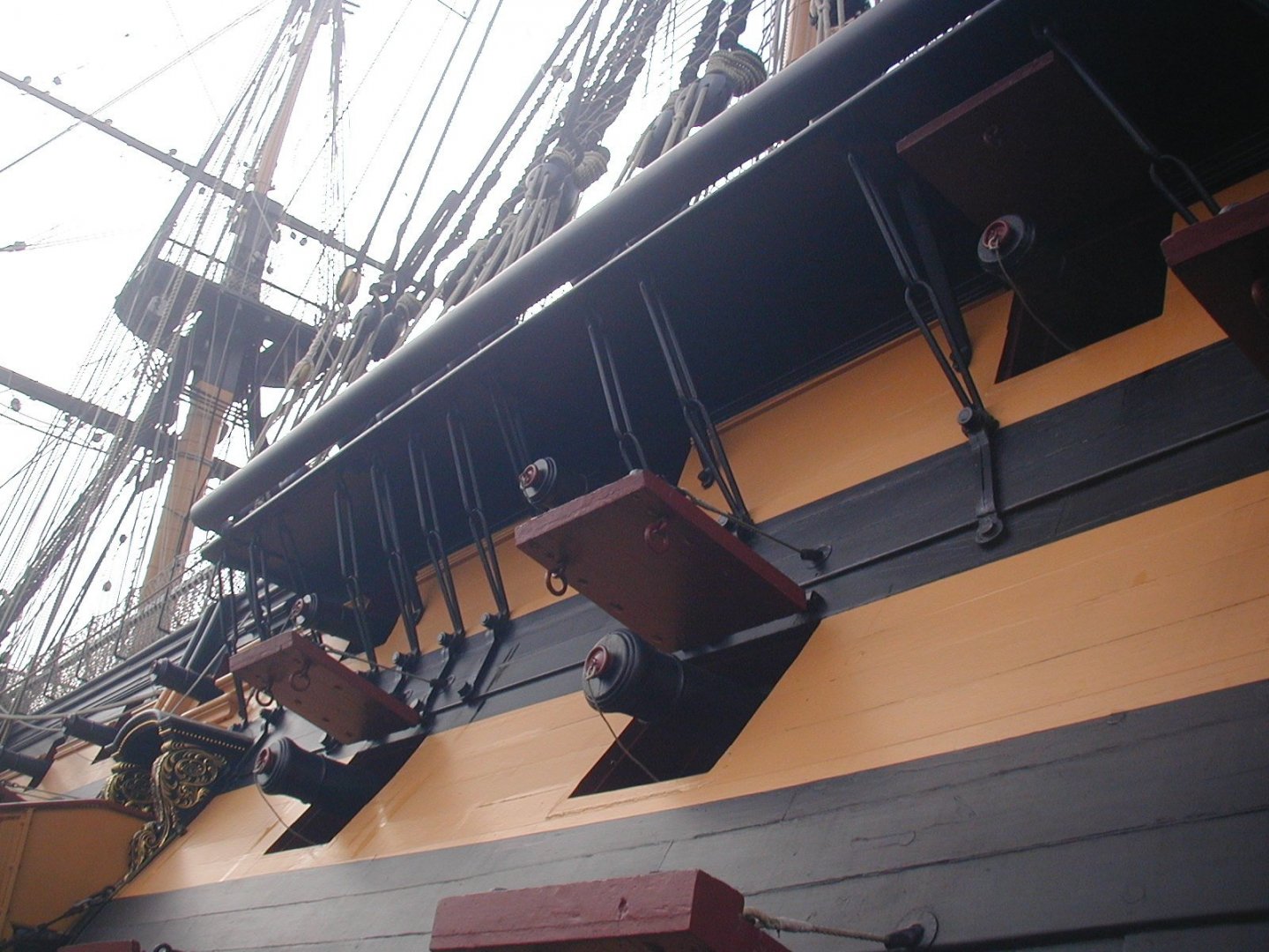
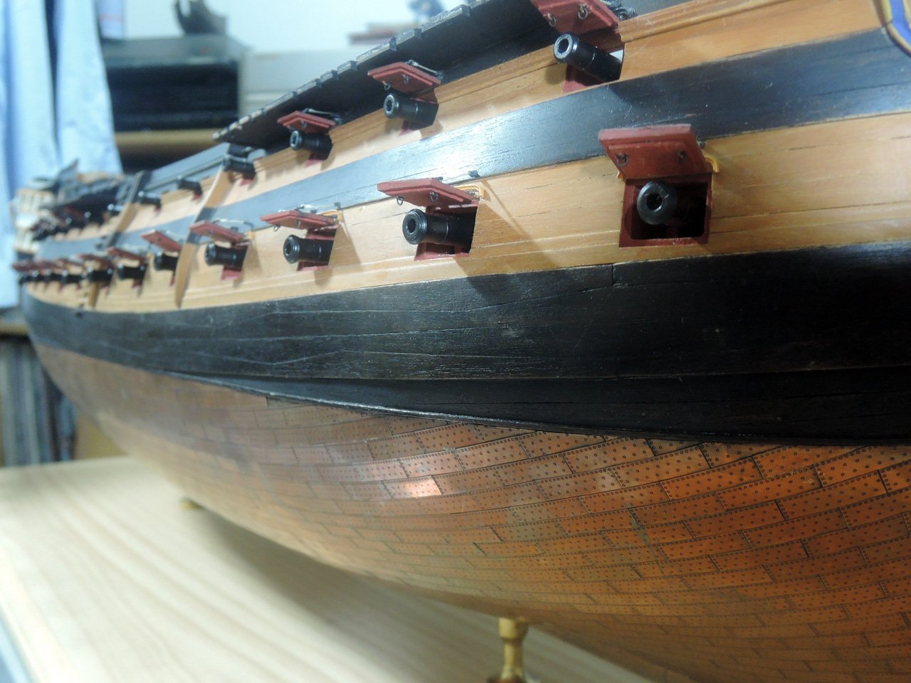
Although details of preventer plates are obscure from a distance, they look nice by looking closer.
Much closer inspection of Victory in Portsmouth reveals preventer plates are made from square metal rod, not round rod as I did, but I think round copper wire are enough acceptable in 1/72 model.
Regards,
- GrandpaPhil and bruce d
-
 2
2
-
-
Alan,
Thanks again for your kind word😄
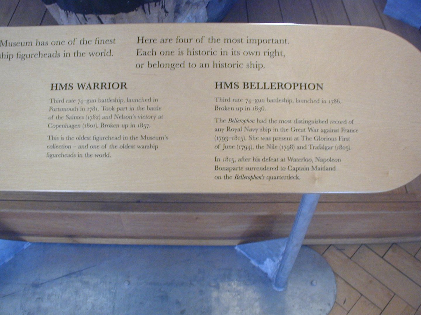
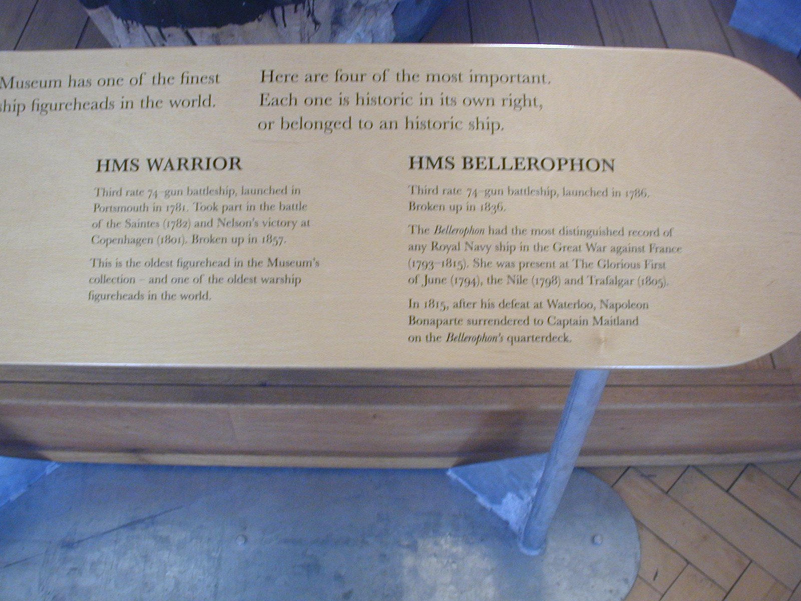
I don't know whole appearance of Bellerophon figurehead, but I’m looking forward how you interpret his appearance on your superb POF model.
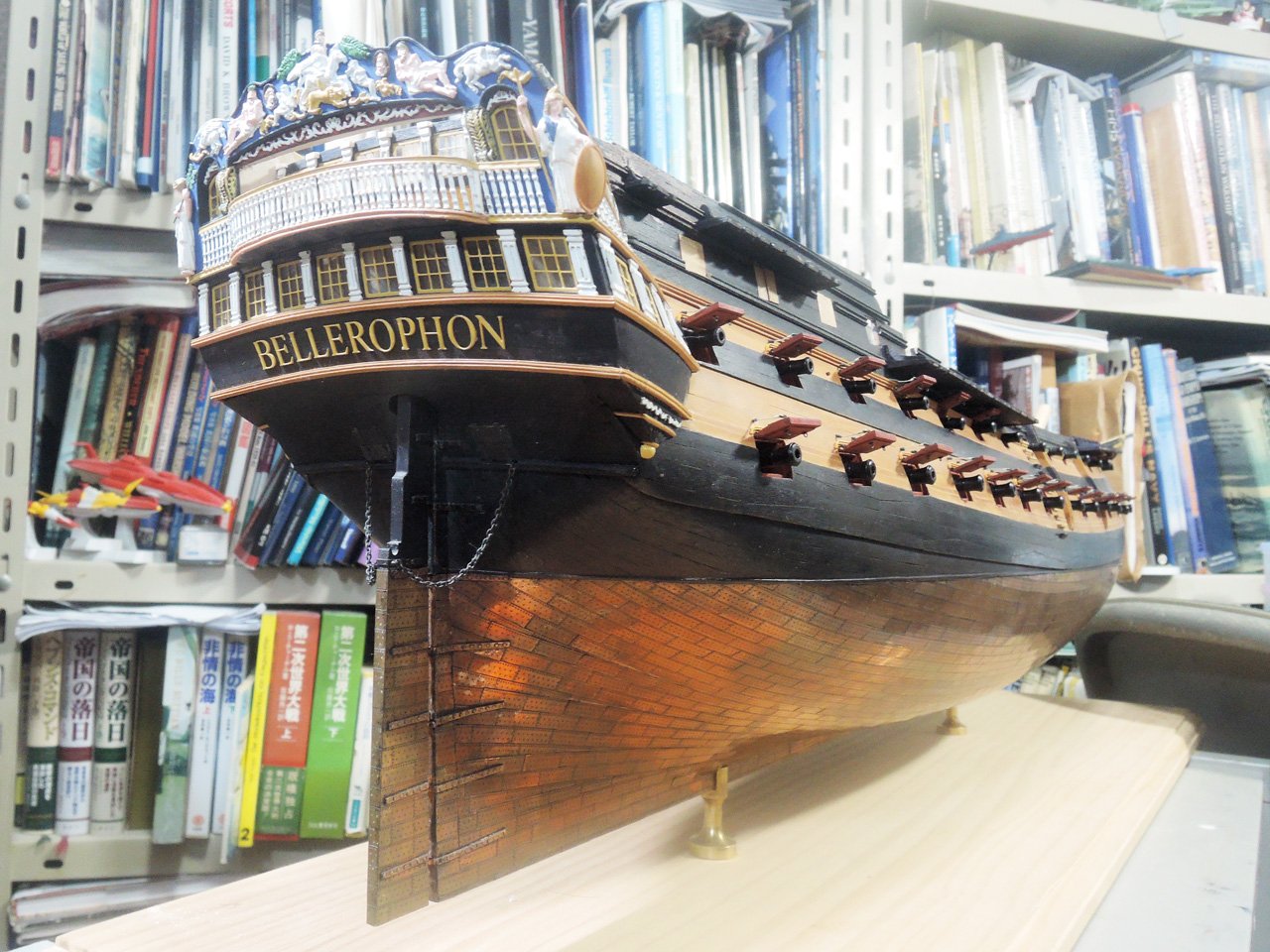
Another subject of decorations of Bellerophon is stern statue which is said to be also salvaged from actual ship.
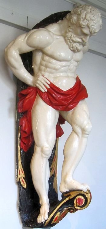
At this stage, I don't employ him yet. But when I finished other important areas of the ship, I want to add him to stern.
Regards,
- bruce d, AON, GrandpaPhil and 1 other
-
4
-
Chains
Next step is installation of chains to channel. But I want to tell about some modification to channel firstly.
Correct reasons I don’t know, but some deadeyes and chains are omitted in kit design when comparing actual plan of Slade designed 74 and kit design.
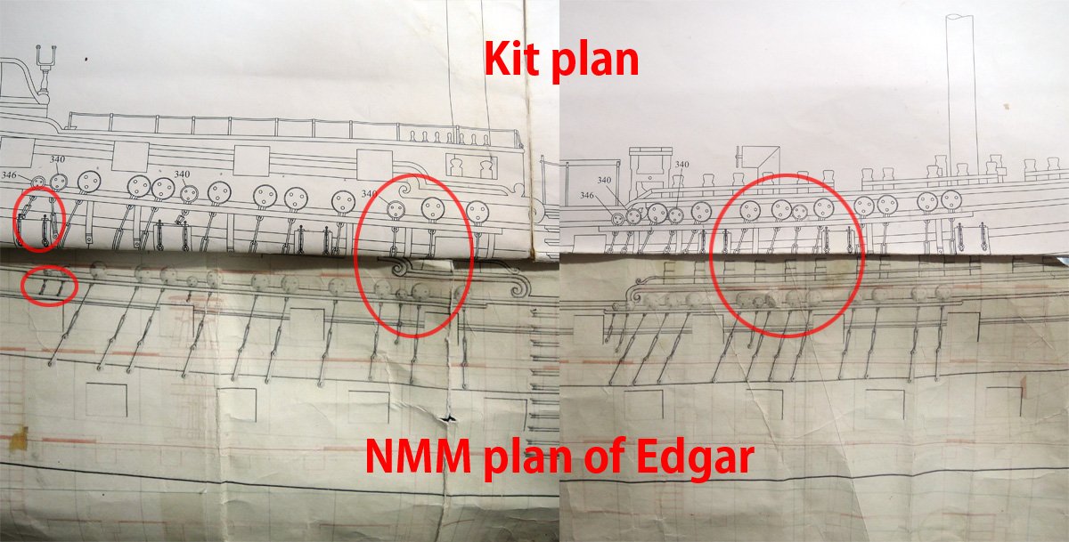
Perhaps kit designer Chris Watton want to escape that channel edge are occupied by deadeyes of slightly larger size from manufactures' stock and deadeyes being crowded each other.
OTOH, AOTS Bellona and NMM Hercules/Thunderer model (contemporary Georgian style hull model with modern rigging) show some of deadeyes are unused.
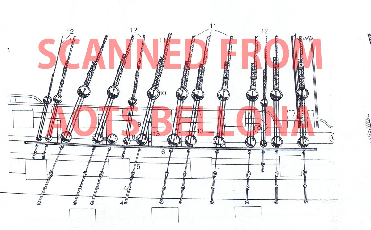
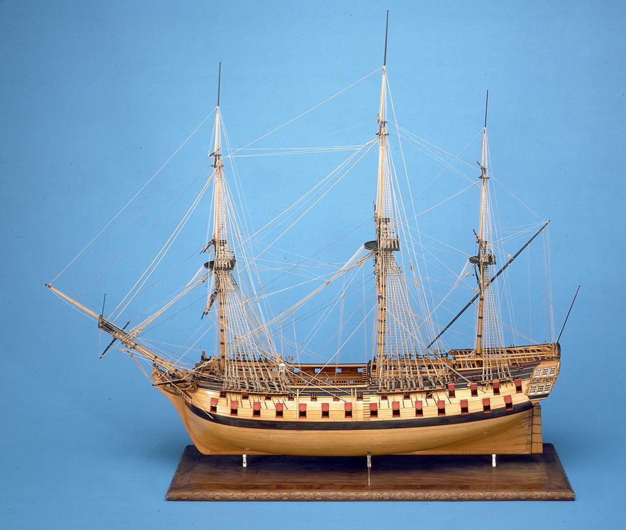
https://collections.rmg.co.uk/collections/objects/66271.html
If they are correct, numbers of shrouds of kit design isn’t wrong. But I decided to add missing deadeyes to channel.
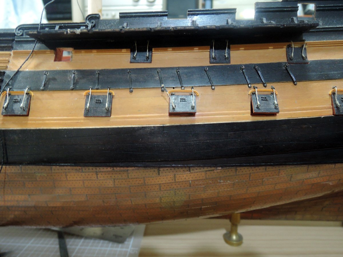
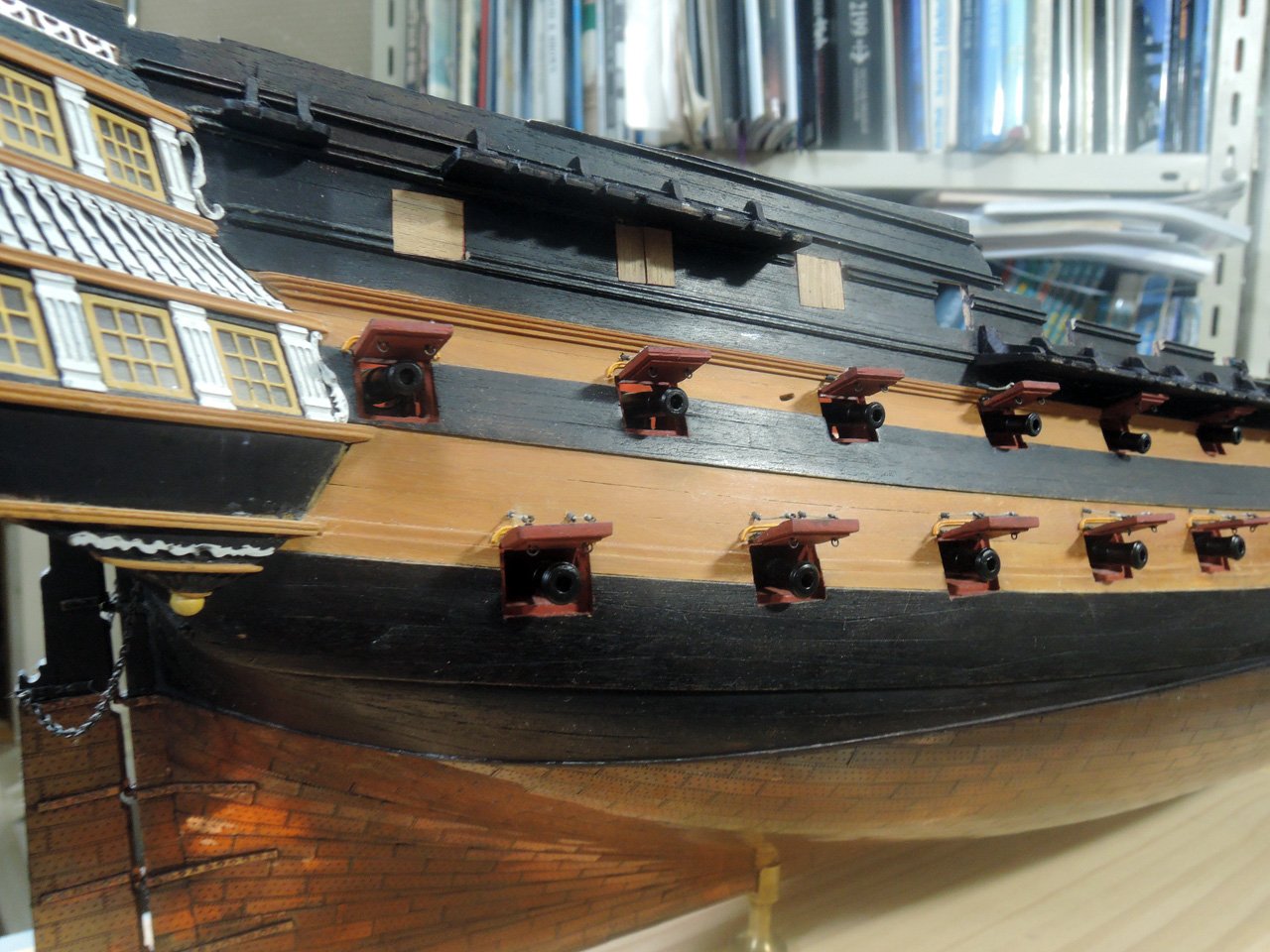
Surely added deadeyes give crowded impression, but I myself am satisfied with result.
Main mast channels are given another modification. Some of chains for backstays are positioned immediately above gunport, these resulted in their chains are lead horizontally, not diagonally as normal chains.
To resolve them, I shortened their deadeye strops, but chains seem to be still horizontal and not strong. Finally I removed aftend of main channels and altered them to stool channels at upper position. This arrangement is also can be seen on HMS Victory today.
Many contemporary models are showing aftend of fore and main channels reducing their width inward and chains of backstays immediately above gunports are still keeping diagonal angle. But I think my modification gave practical solution.
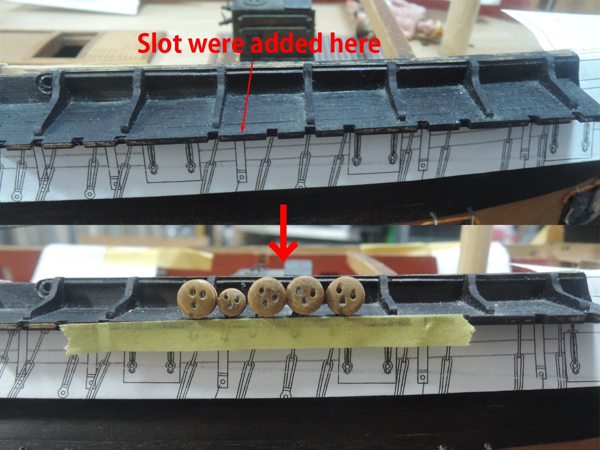
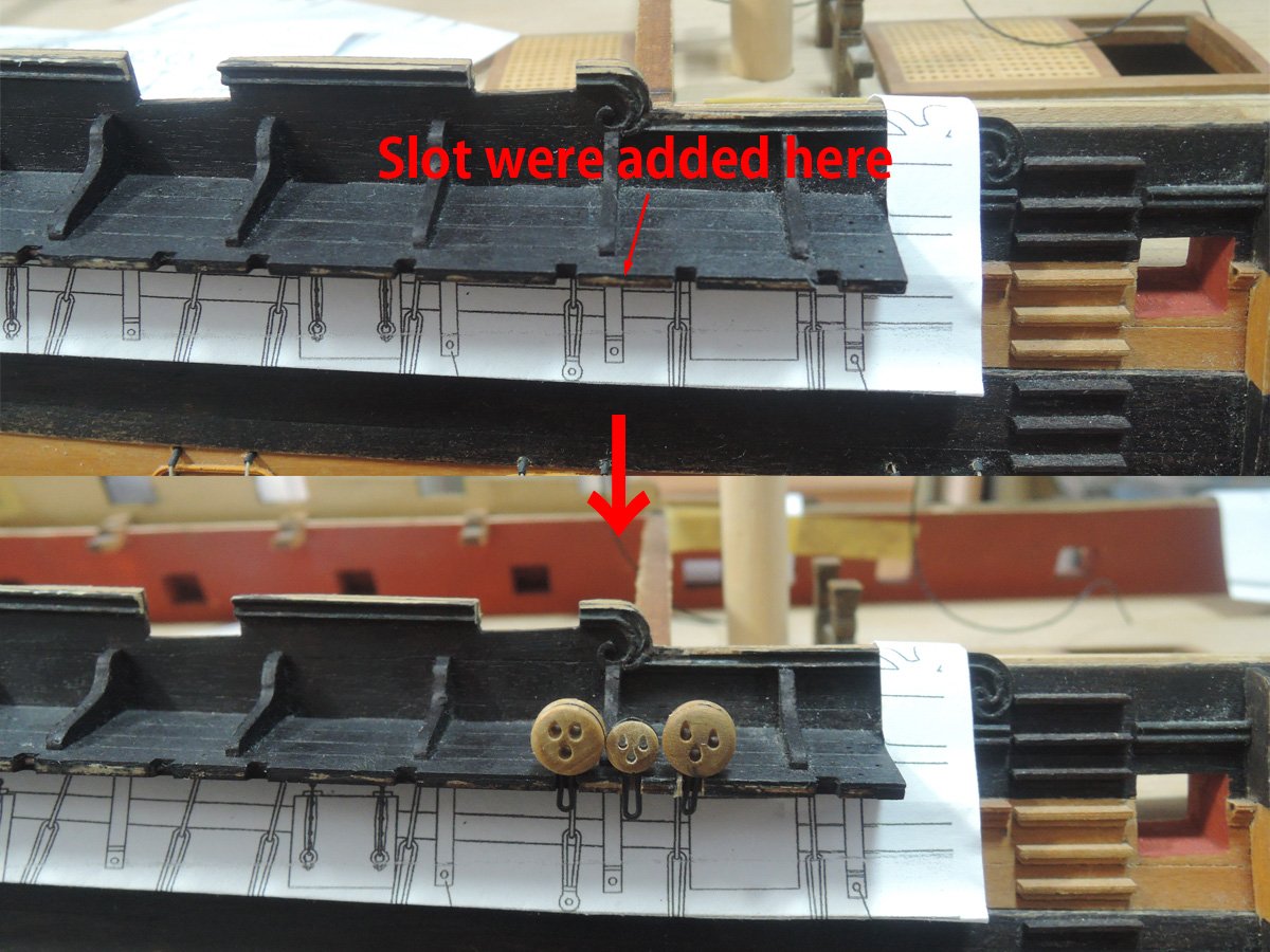
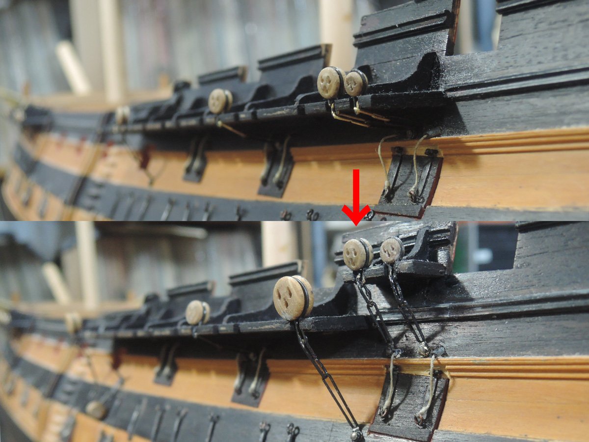
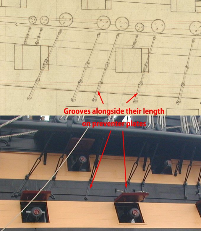
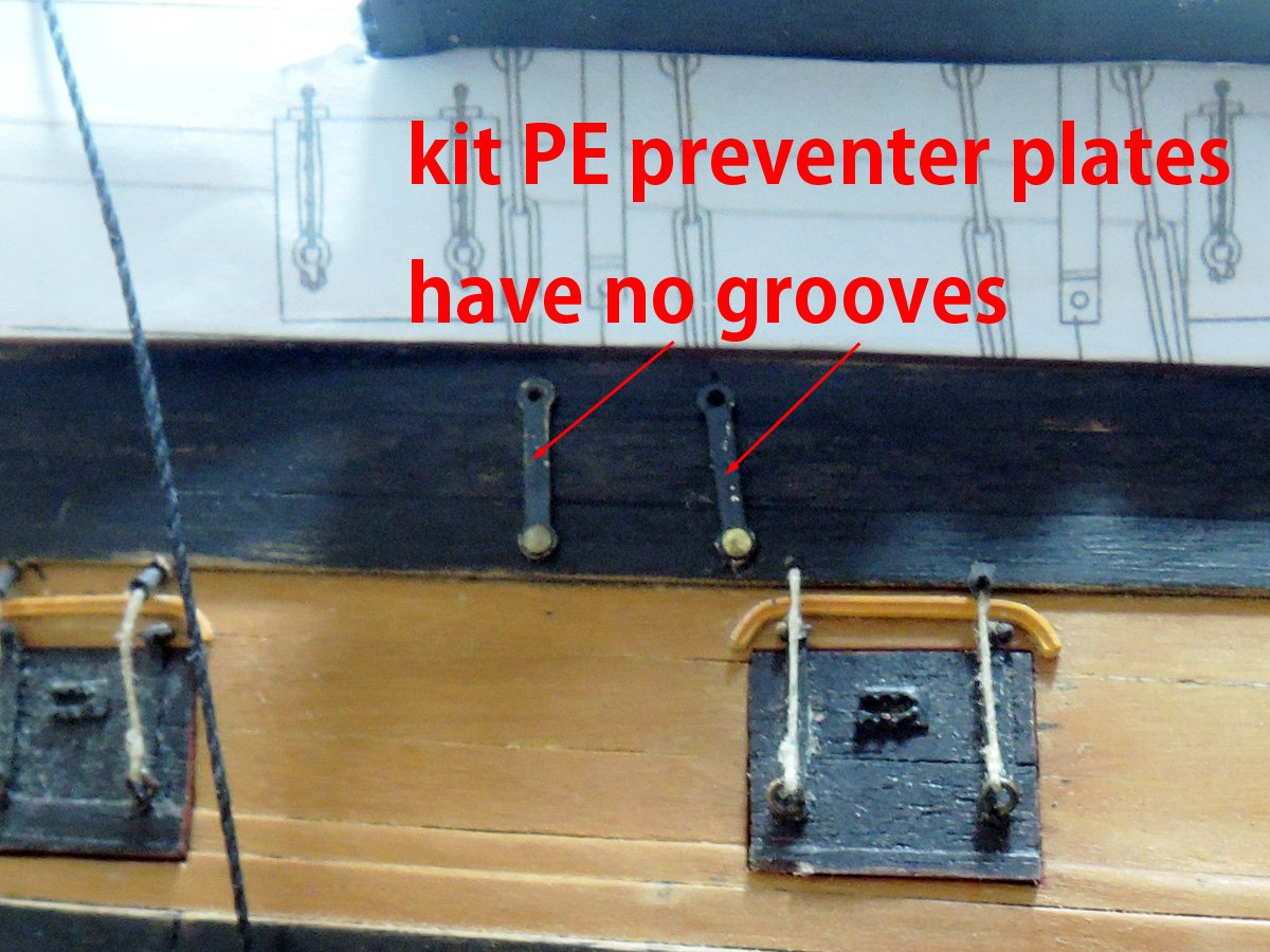
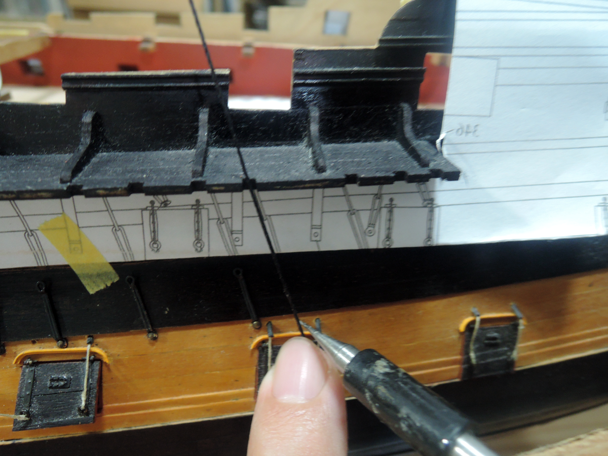
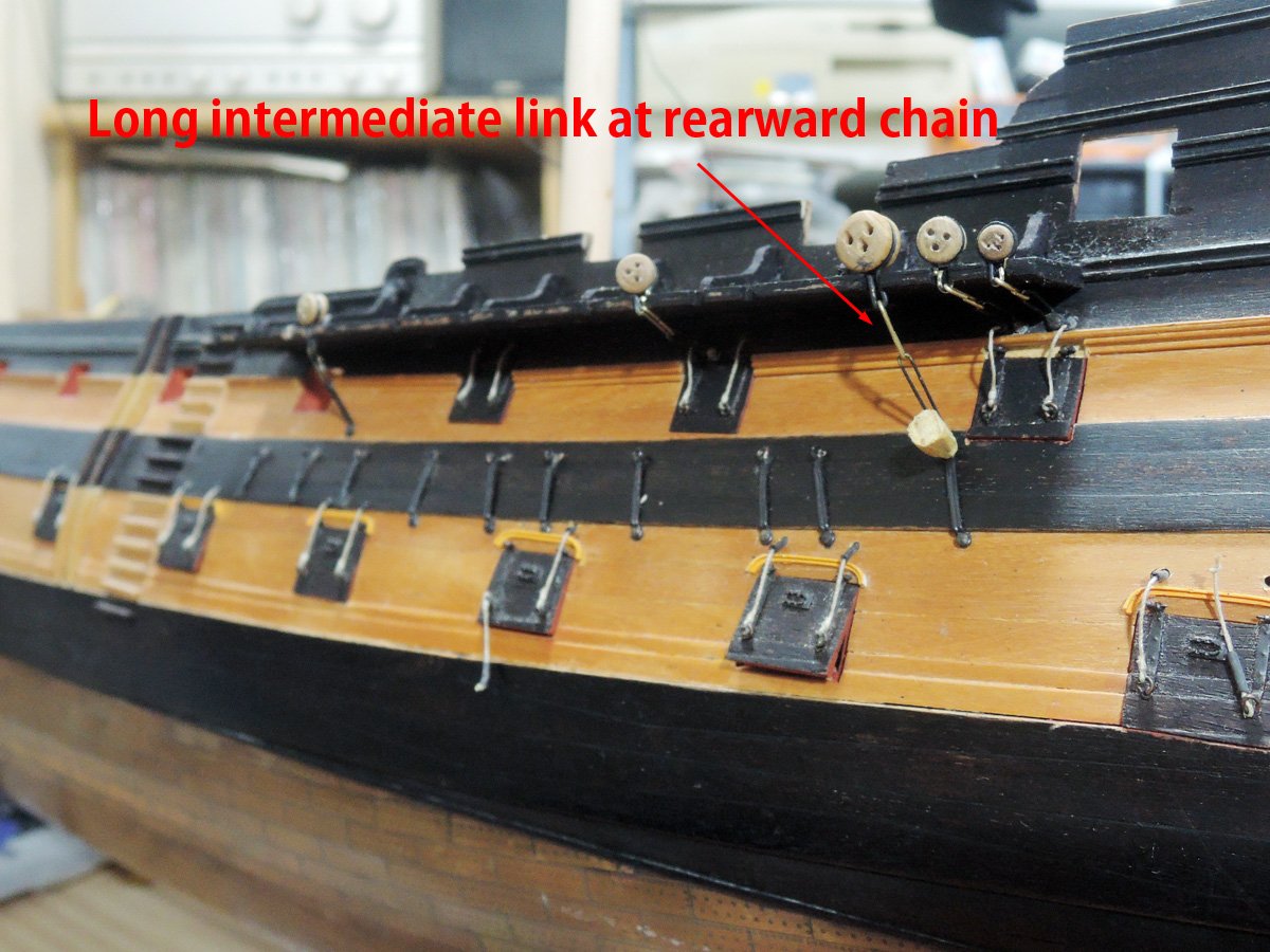
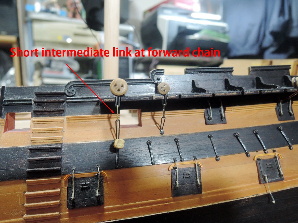
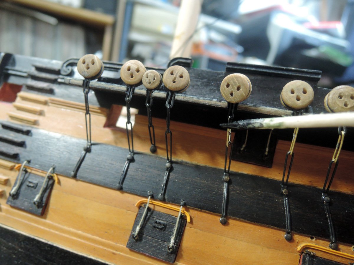
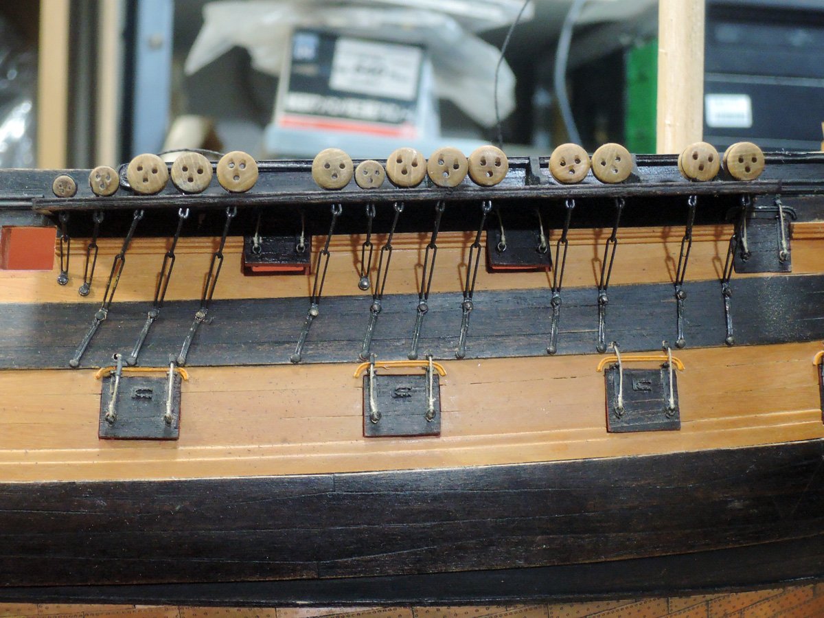
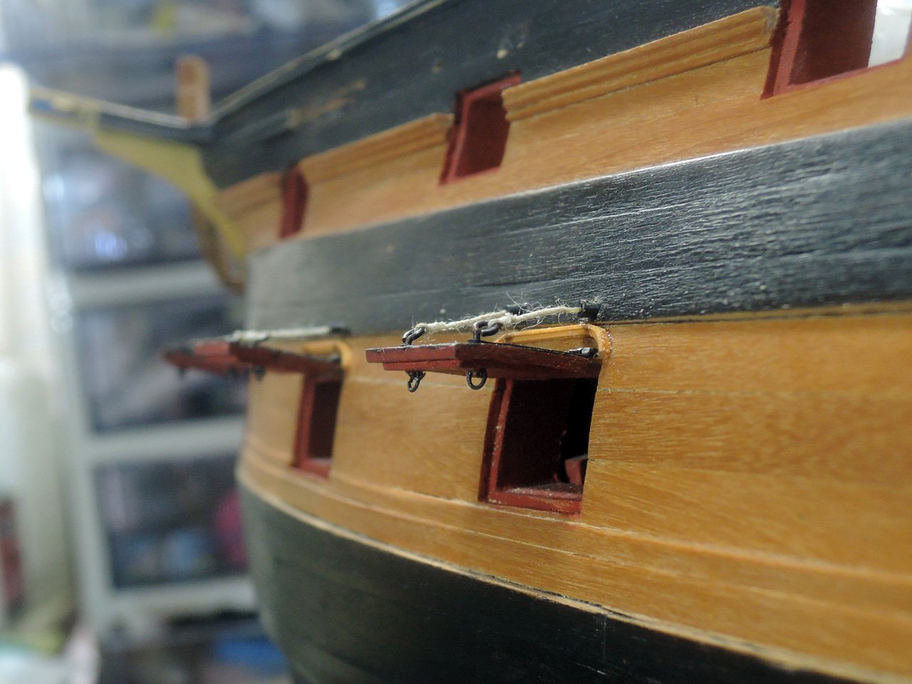
Now it’s time to tell about chains themselves. PE chain parts are also one of few disappointments of the kit. While each chain assembling should have different length according to its position, kit PE parts are same size. Also preventer plate should have groove alongside their length, but kit PE is merely flash surfaced.
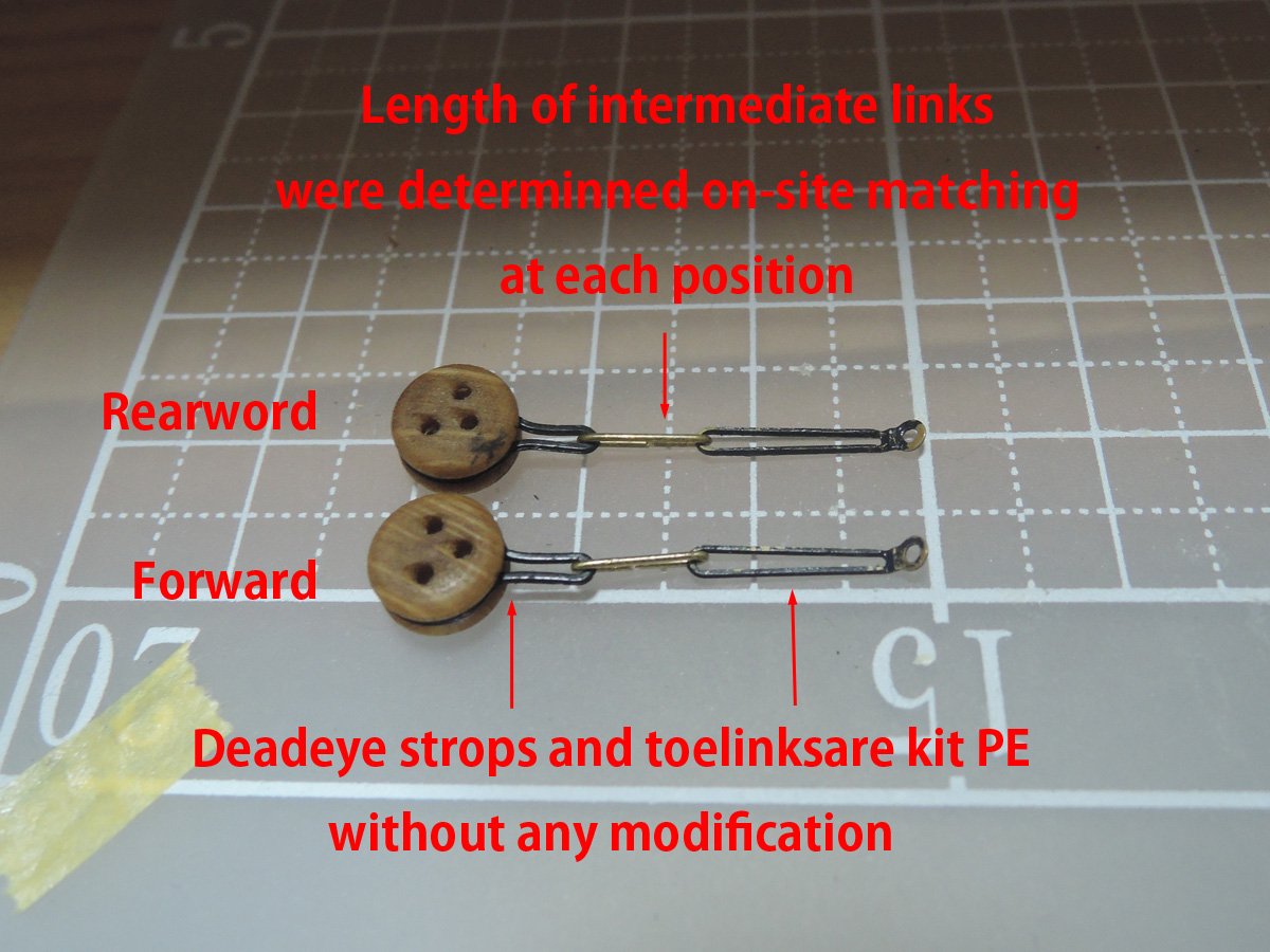
Finally, I decided to make preventer plates and intermediate links by myself. Difference of length of each chain assembling will be controlled by length of intermediate links. I think deadeye strops and toelink in kit PE need no modification.
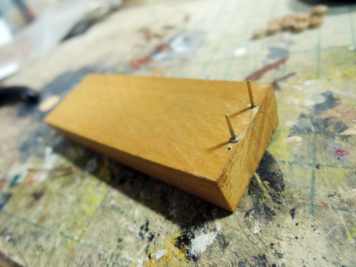
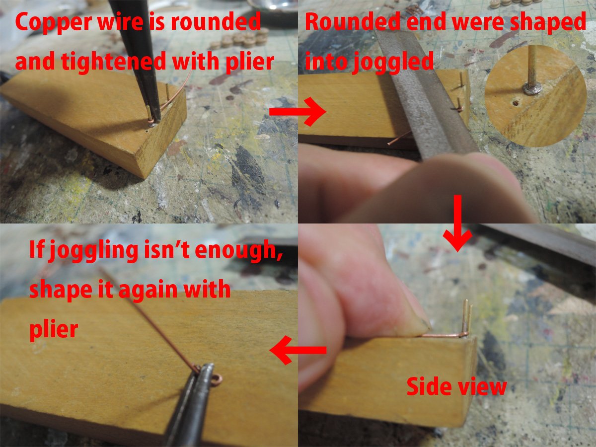
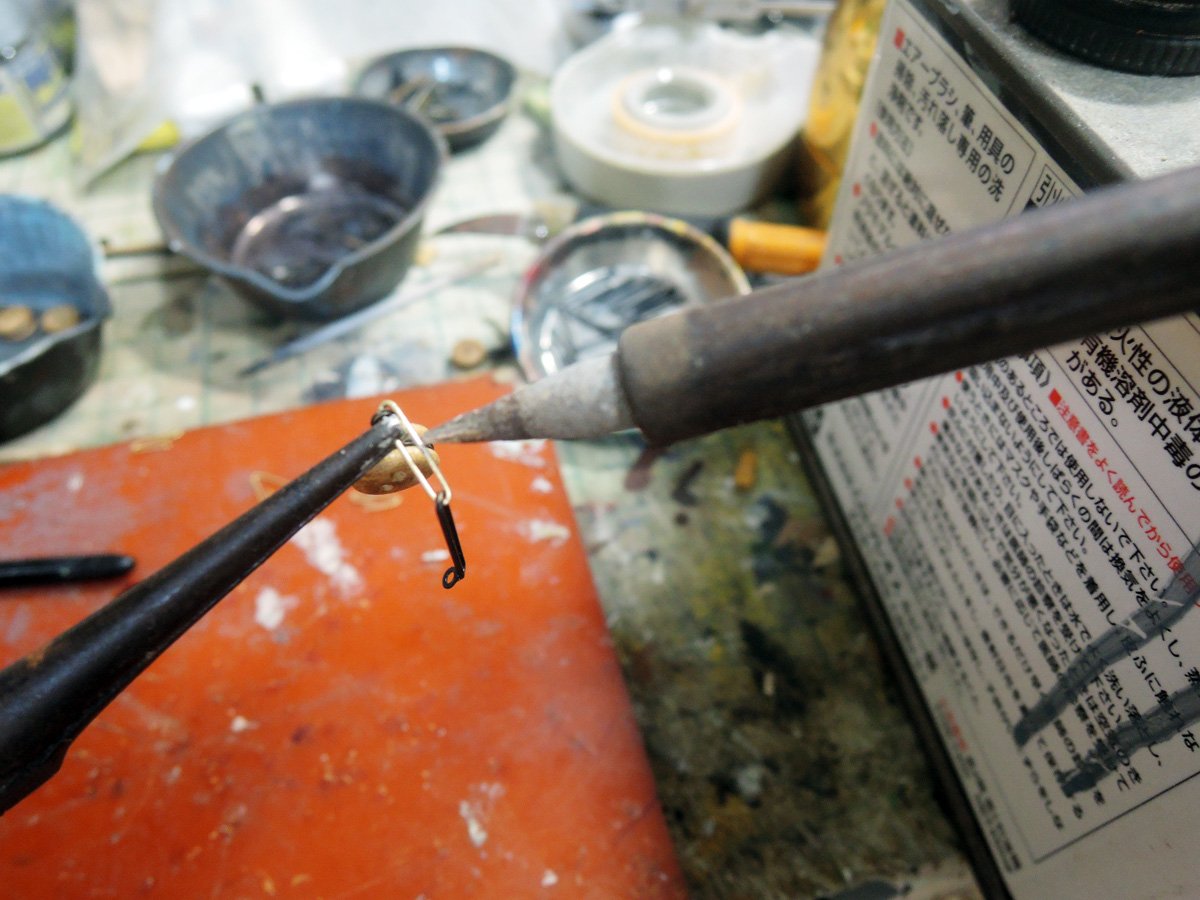
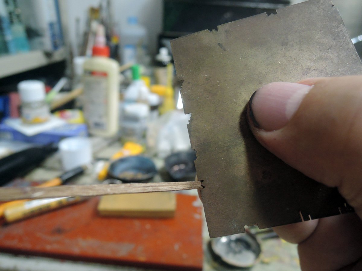
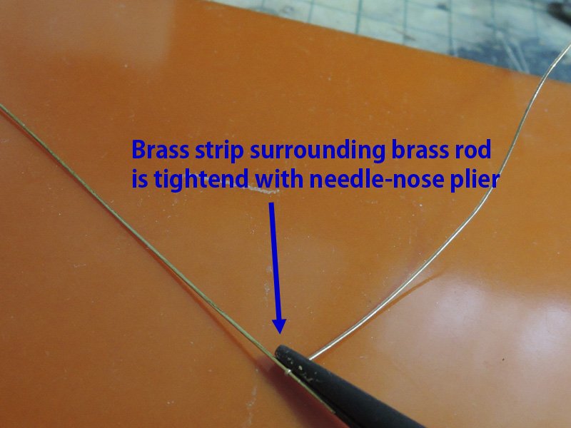
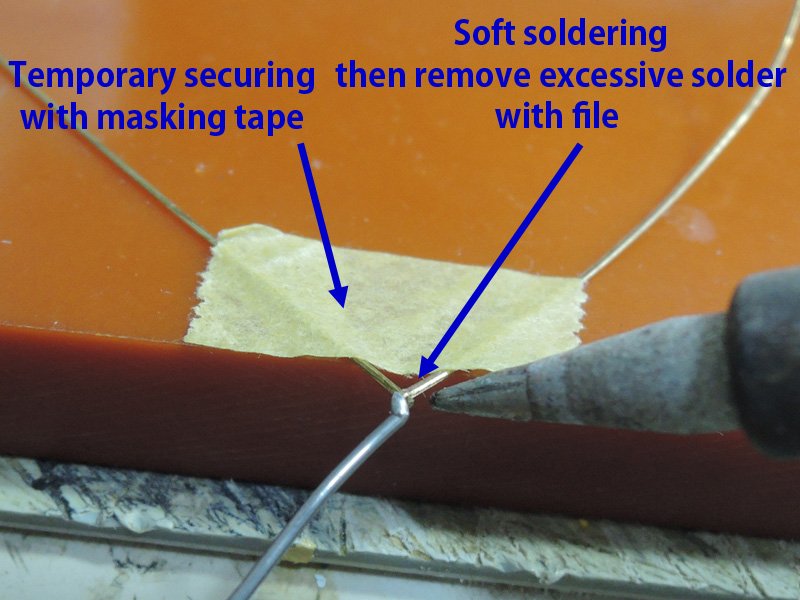
Preventer plates were made from copper wire with soft-soldering. Maybe I should use brass rod and silver-soldering, but preventer plates don’t directly receive upward forth of shroud. So I use easier material to bend.
Photos themselves tell how I made them than word, so no detailed depiction will be required.
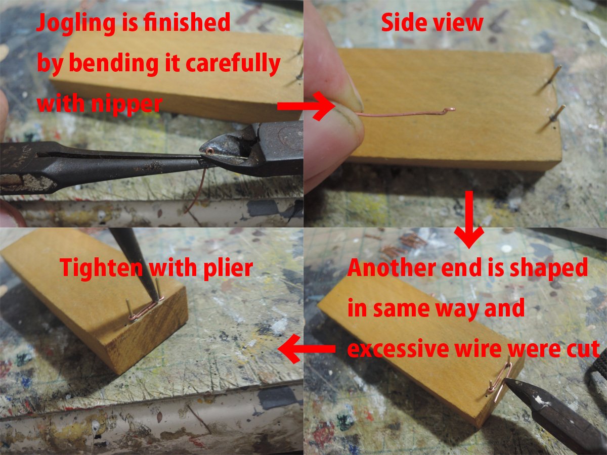
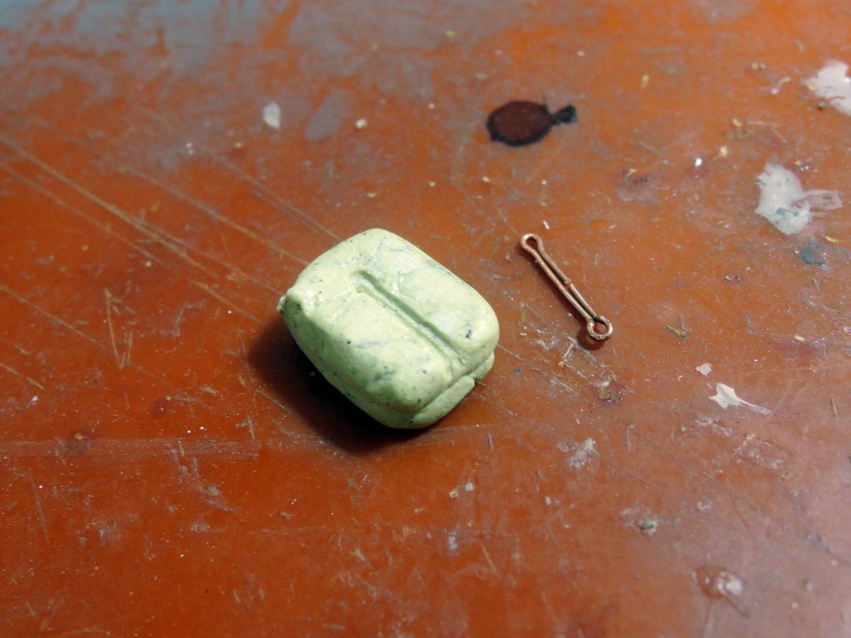
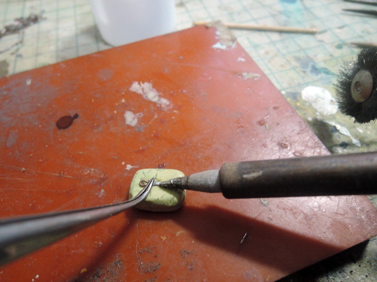
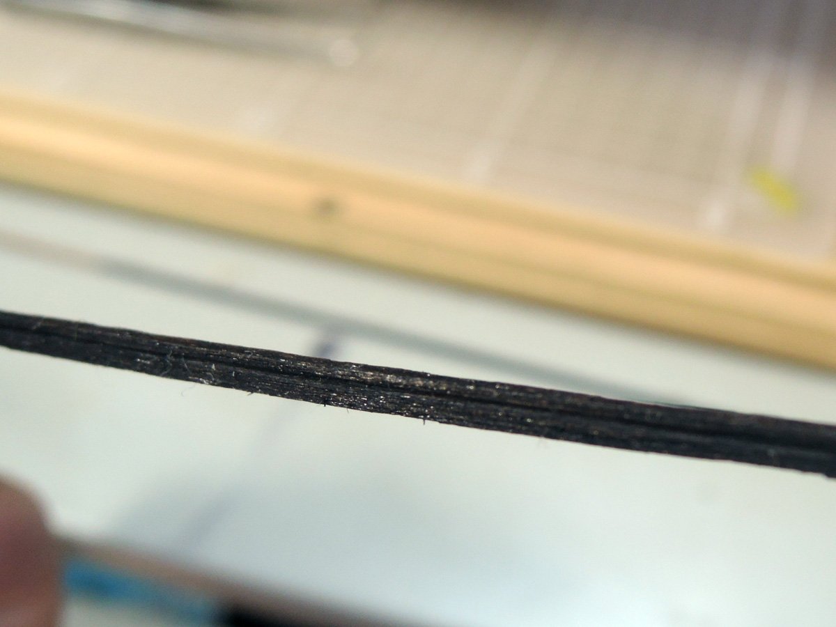
I soft-soldered rearward side of plates, but it is unavoidable solder is flooded into outer surface. So I grooved by file.
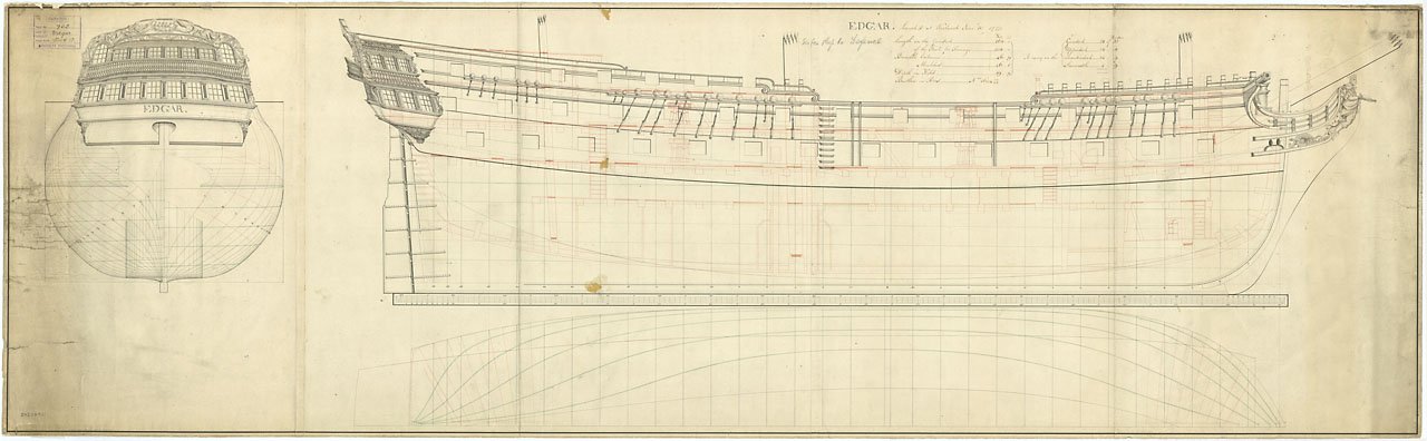
BTW, NMM Elephant plan shows two sizes of preventer plates. Fore channels ones and foremost three ones are short and rest are long.
https://collections.rmg.co.uk/collections/objects/81038.html
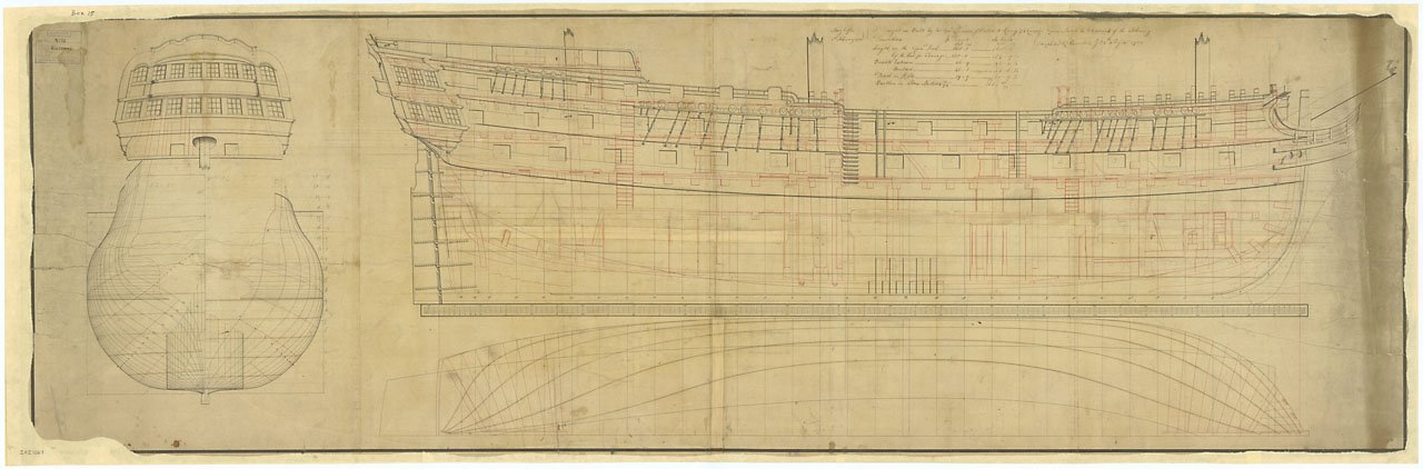
OTOH, Edgar and other Elephant plan show longer preventer plates are used on foremost two chains of fore channels and they seem to be even longer than main channels ones.
https://collections.rmg.co.uk/collections/objects/80682.html
https://collections.rmg.co.uk/collections/objects/80855.html
I decided to make two sizes of preventer plates for easier work. Also if I add billboard at later stage, plates of different size will be hidden.
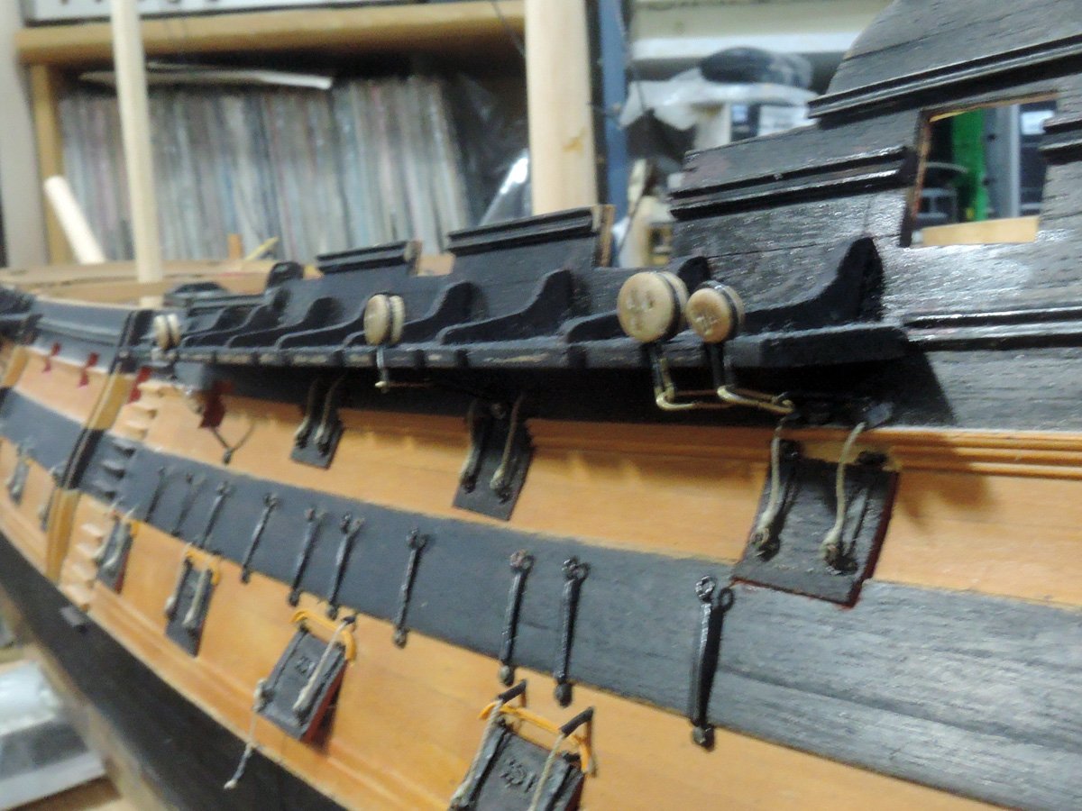
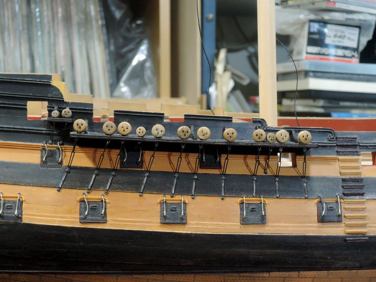
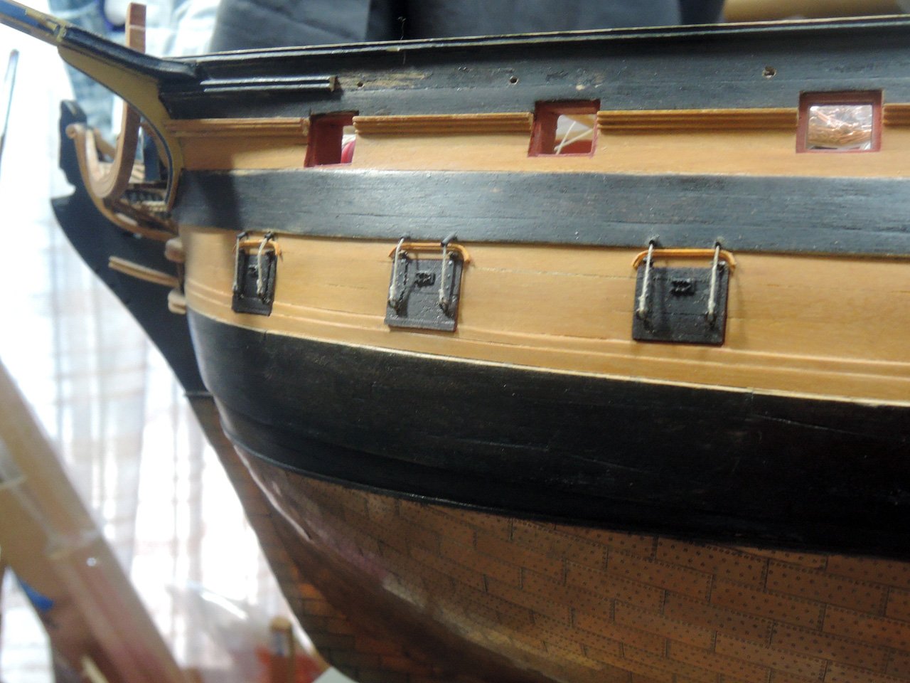
After their completion, preventer plates are fitted to hull but only pinned at lower hole. Upper hole will be pinned with toelinks later.
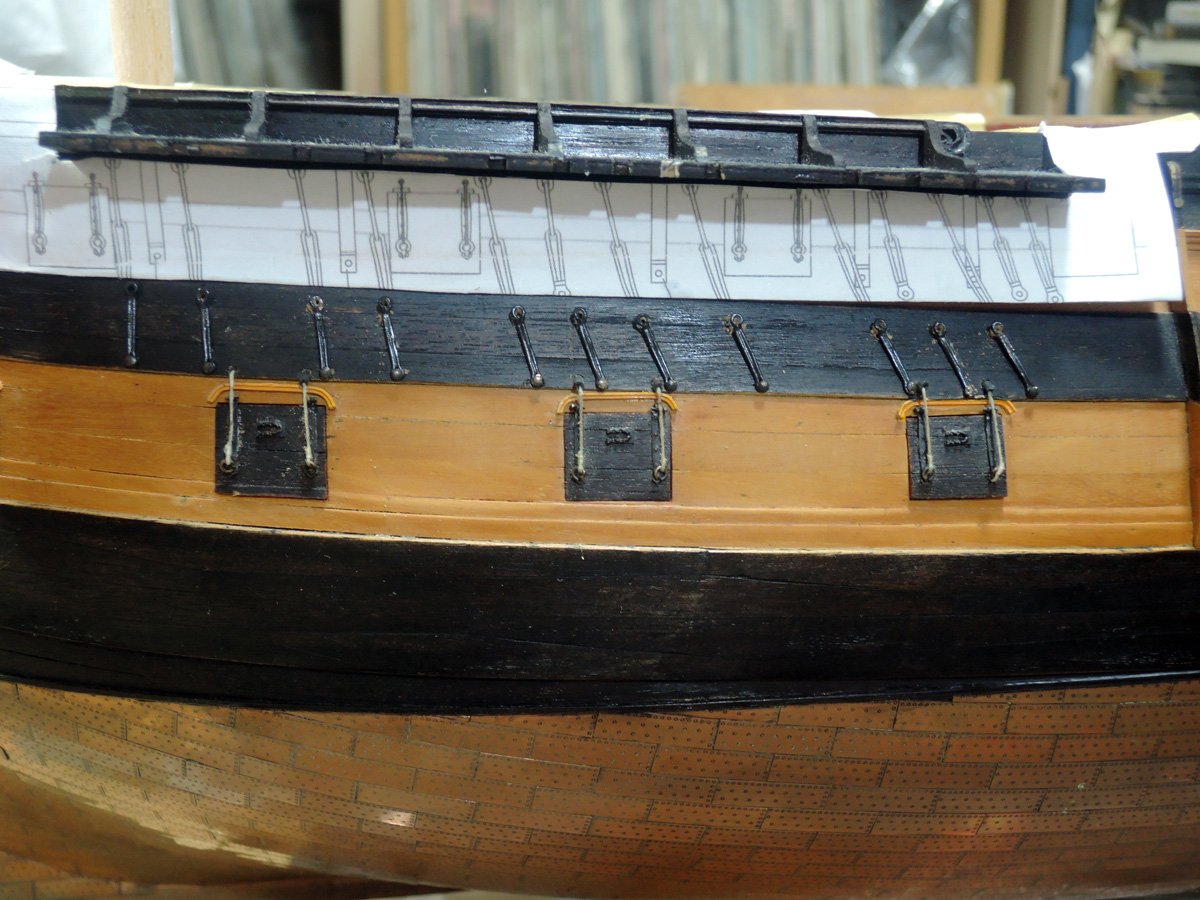
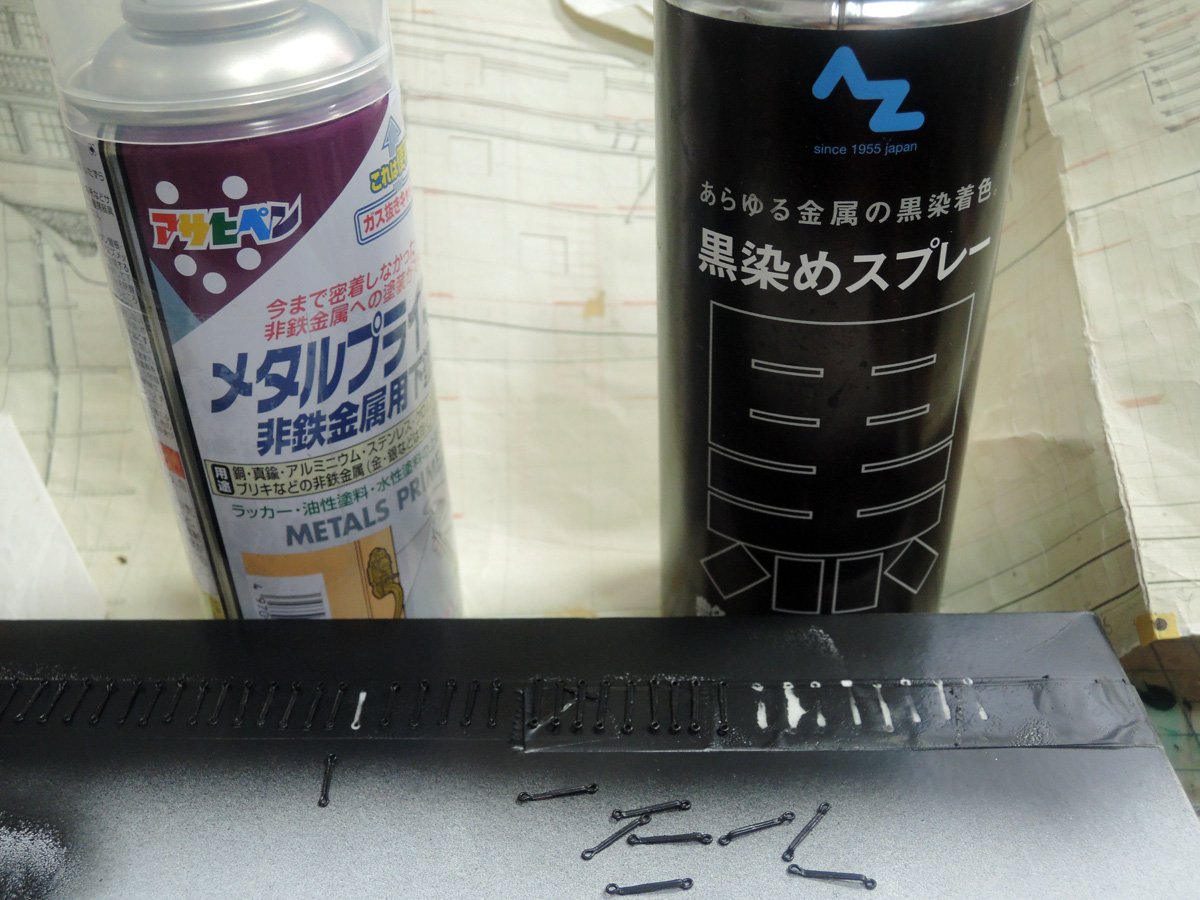
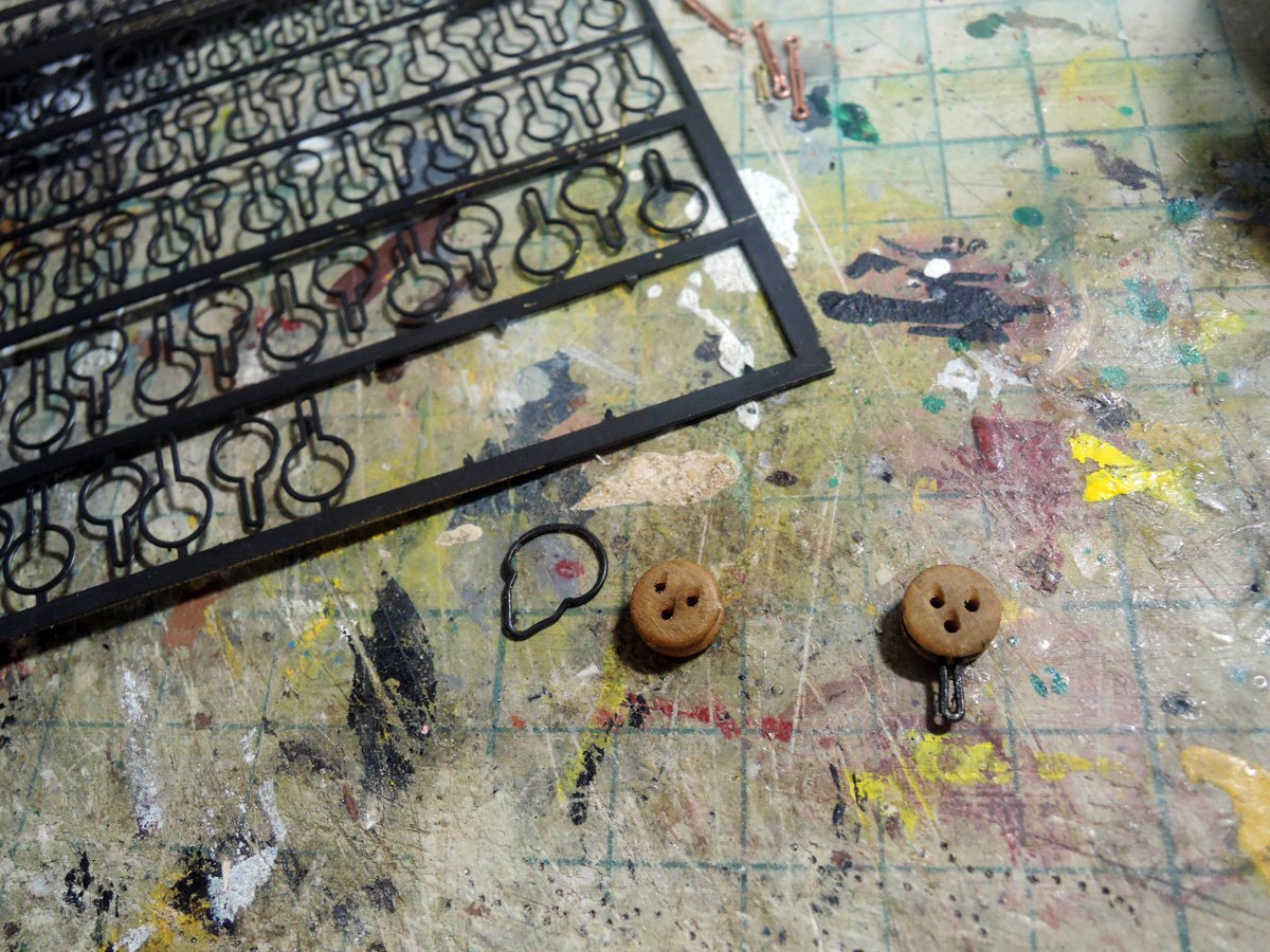
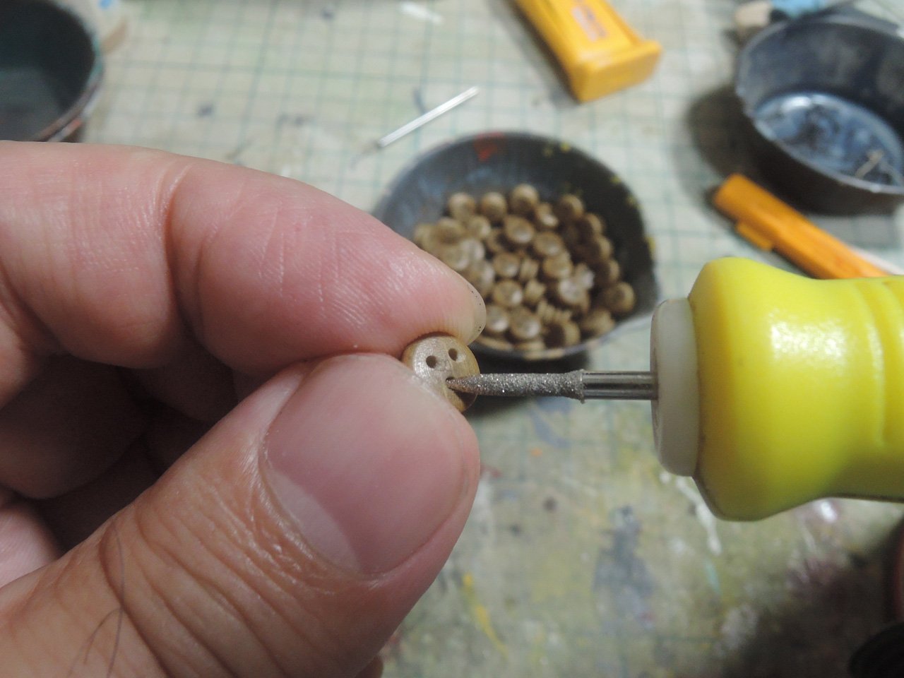
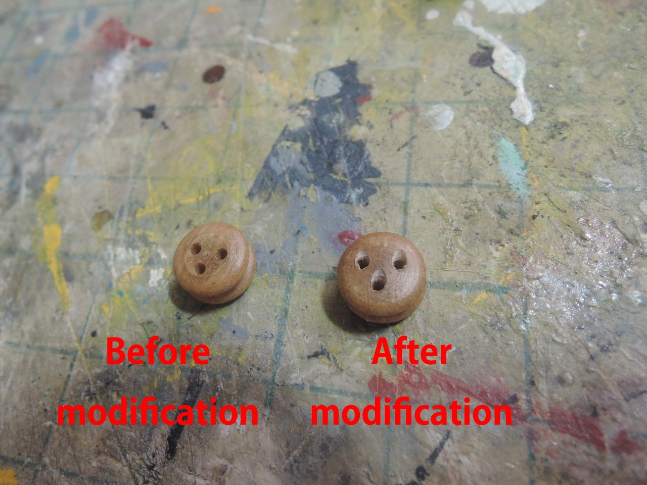
Some building guide books tell that assembled deadeye and chains can be chemically blackened as whole assembling. But I’m afraid that this method ruins surface of deadeyes. I blackened chain parts with Asahipen Metal Primer and AZ Blackening Spray before assembling them. They work well and blackened layer of strop is tough enough to endure against bending force when fitting deadeyes. BTW I add some modification to deadeyes. Top edge of each holes are recessed with electric tool.
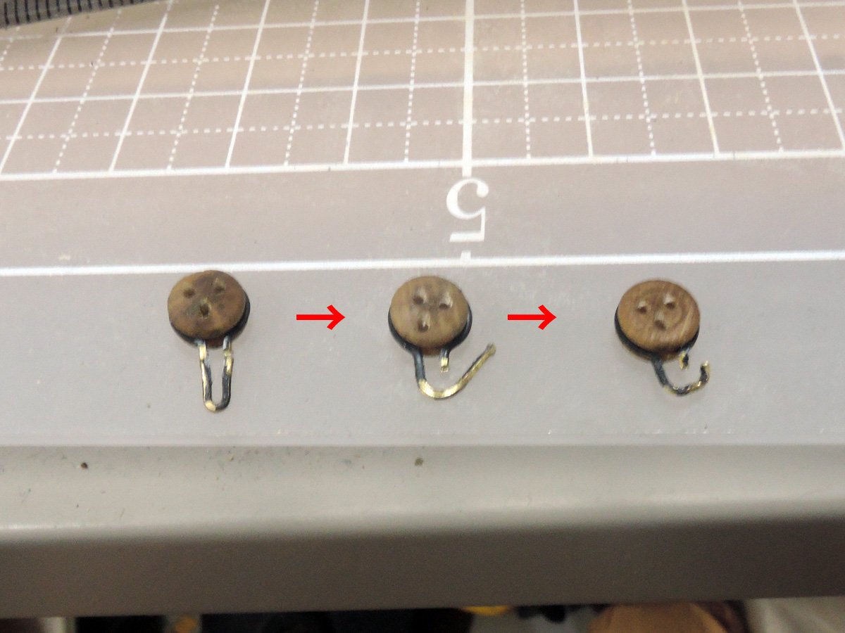
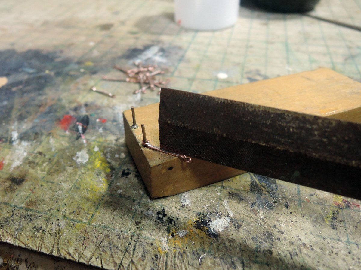
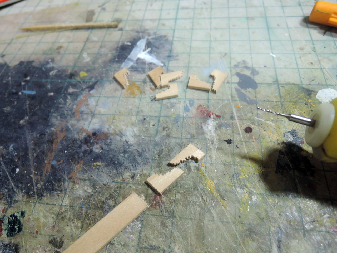
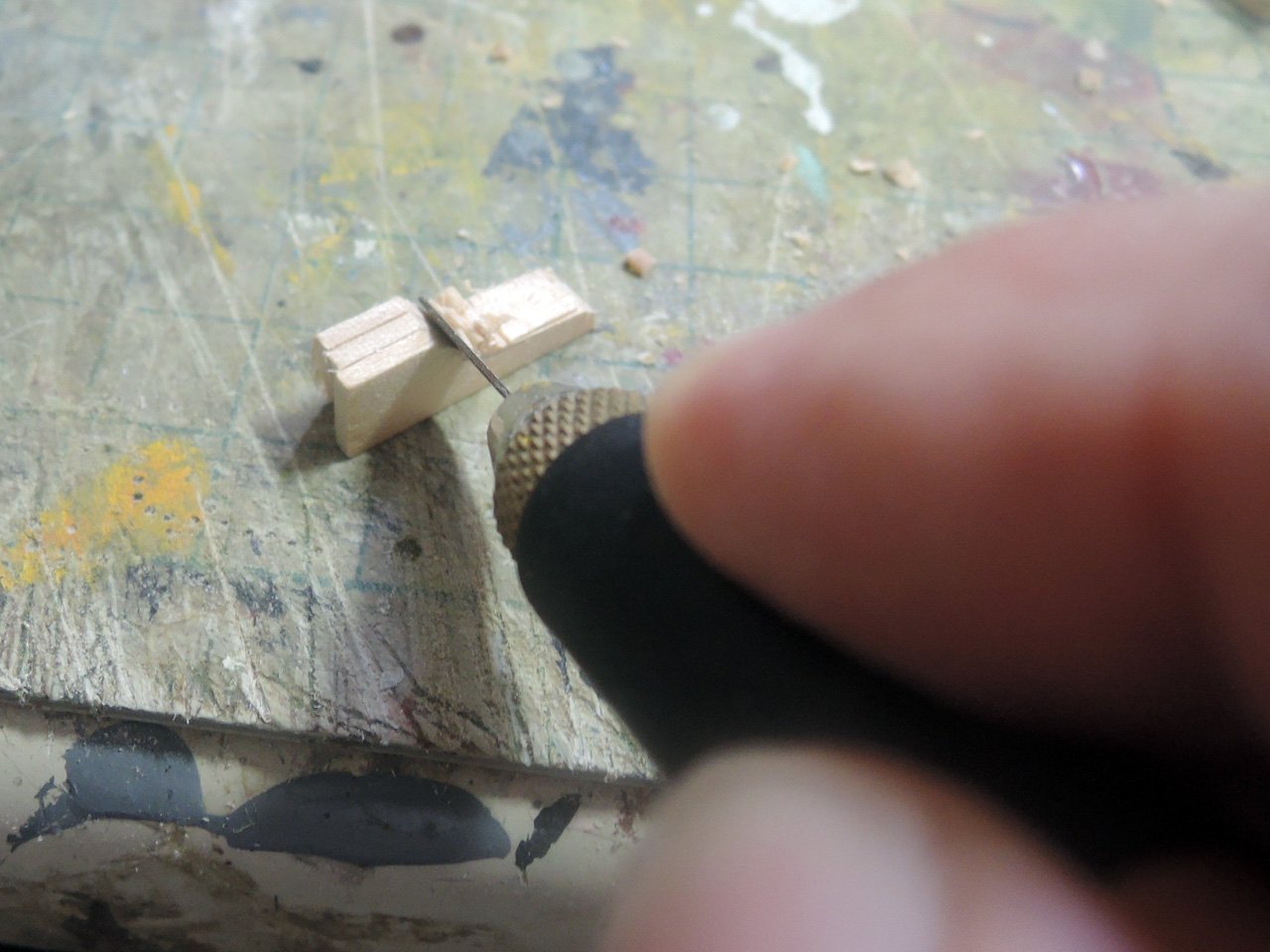
Making of intermediate links are also told by photos themselves. Before I started them, I expected depressing work requiring long time, but it finished within much shorter time than I expected. intermediate links require strongness than preventer plates, so I used 0.5mm brass rods.
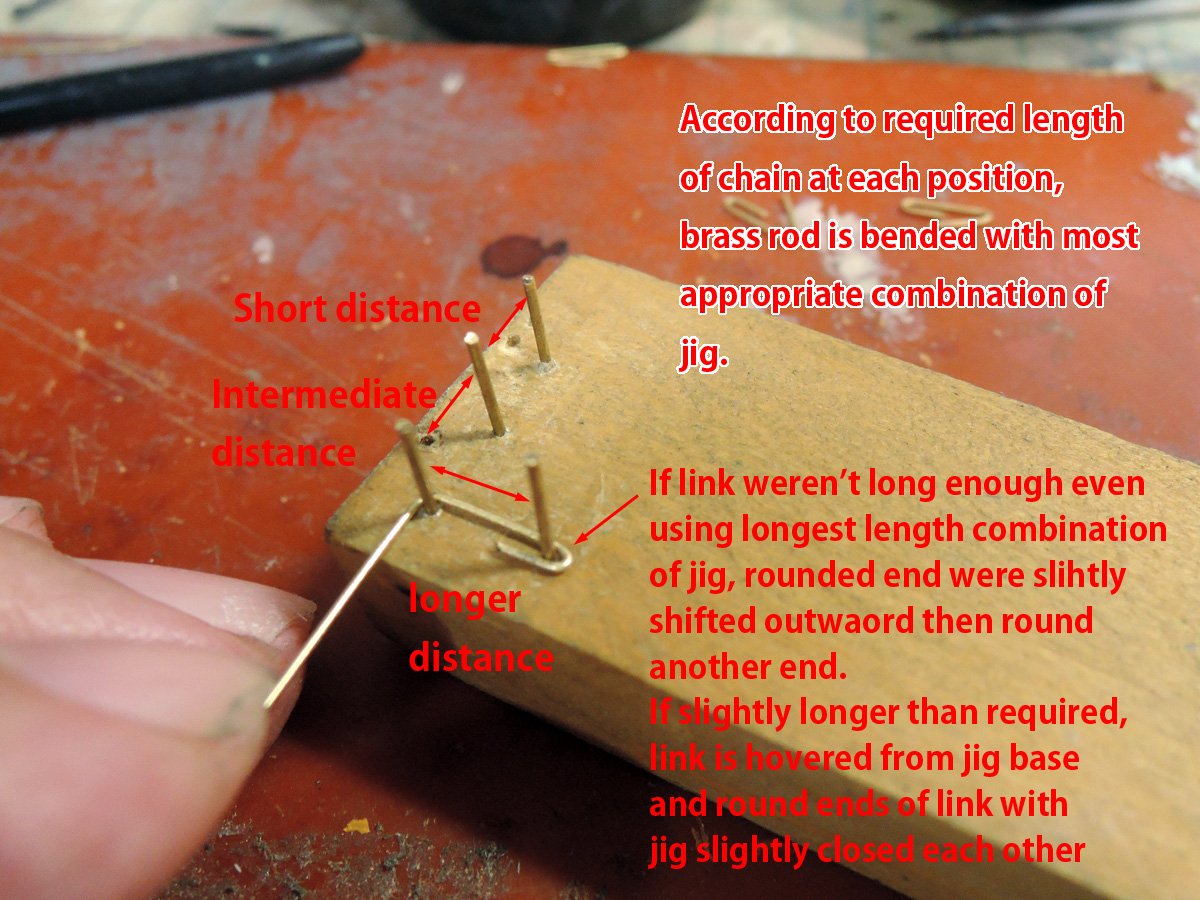
If test fitting is OK, then soft-solder it. Soft-soldering gives enough strongness unless changing shape of link with strong teightning. Butt end of each link is positioned at rearward for beautiful result.
Intermediate links are blackened on-site. I use toothpick and apply AZ Blackening Spray once prepared on another tray.
Capping pieces are moulded and fitted to channel edges. I used walnut strips included in kit. Boxwood would be better choice for moulding, but I used easily available material.
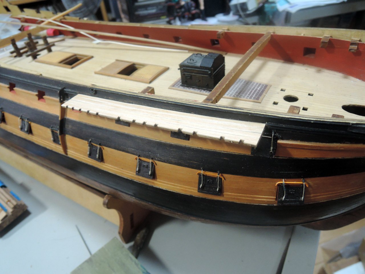
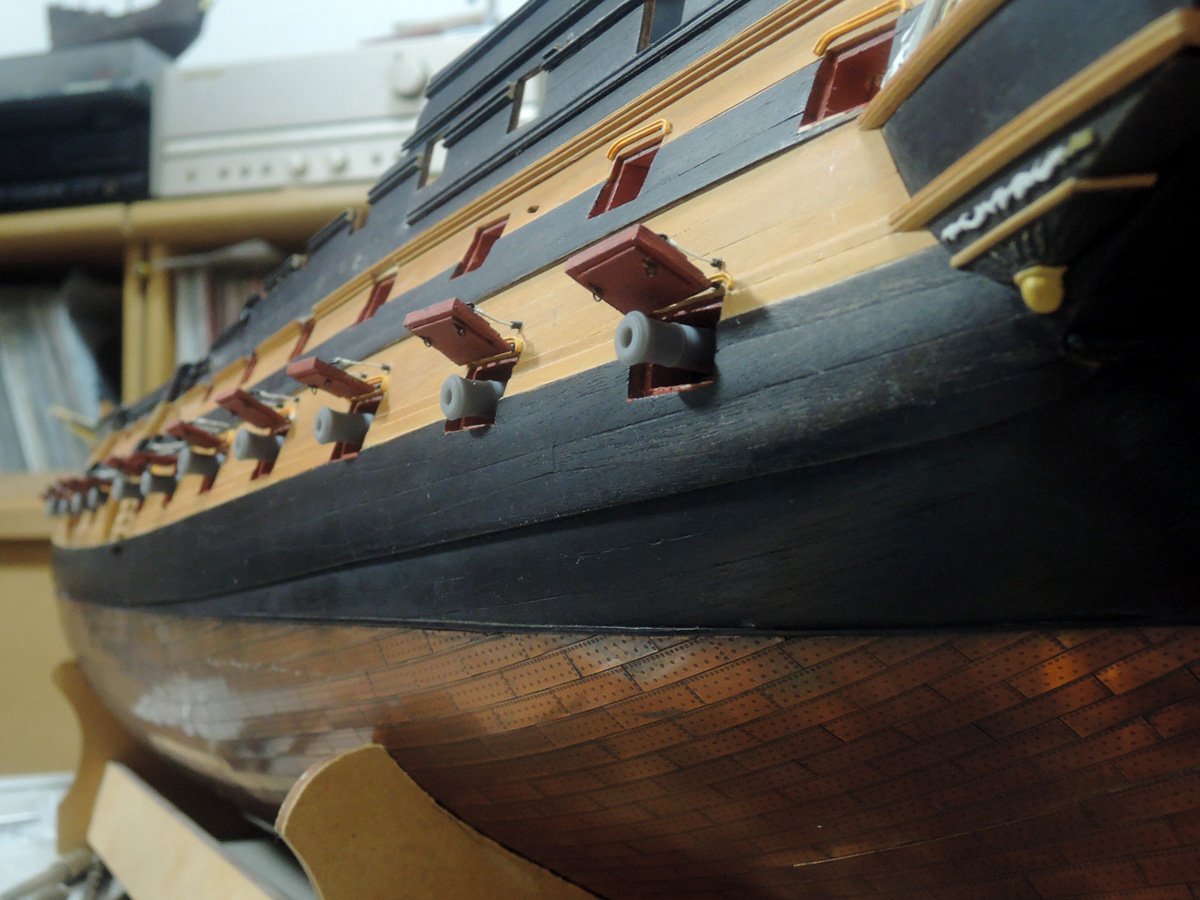
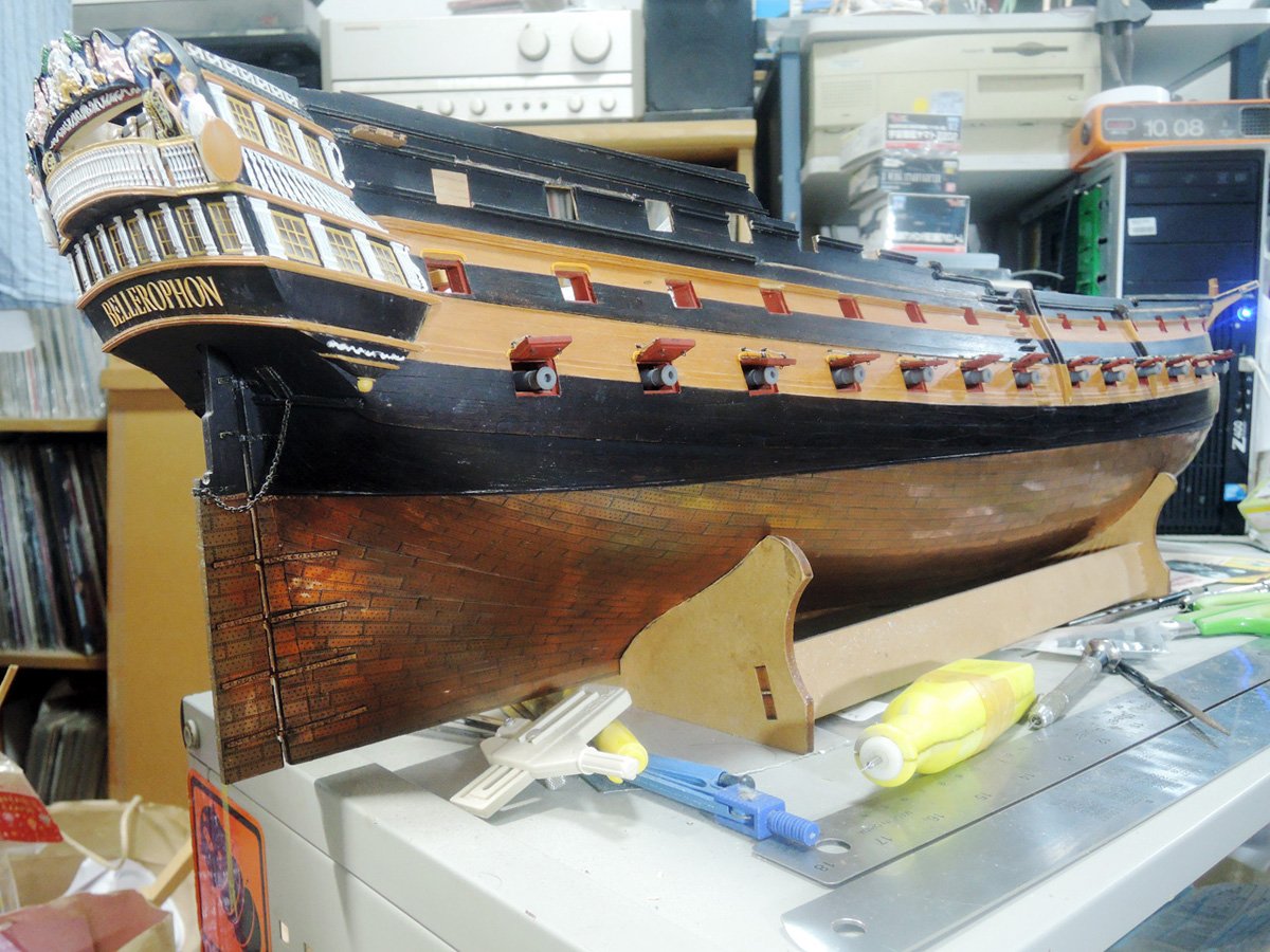
Bellows are latest status of my building.
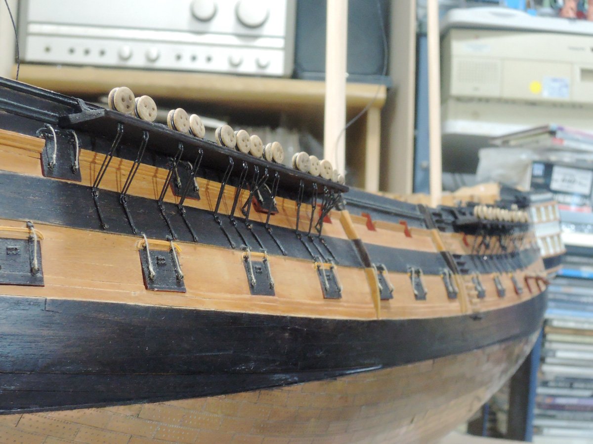
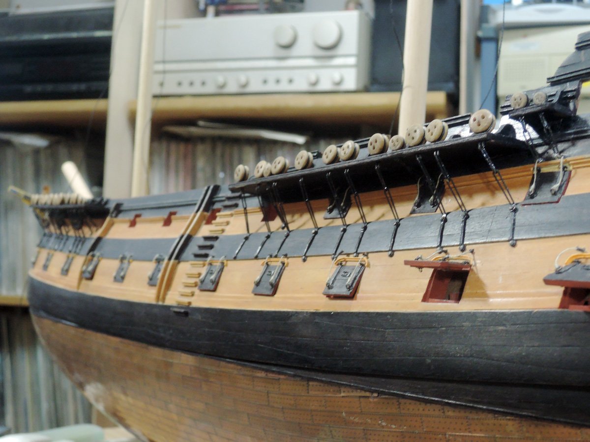
Next, I want to finish rest of external hull fittings except mizzen channel area.
- chris watton, BenD, mort stoll and 9 others
-
12
-
Channels
Channels are basically lasercut walnut included in the kit, but I added some modification. Curved strips cut from 0.5 mm maple sheet were laid down to represent actual channel construction.
Outermost strips were glued with larger size, then cut along outline of kit parts after glue dried.
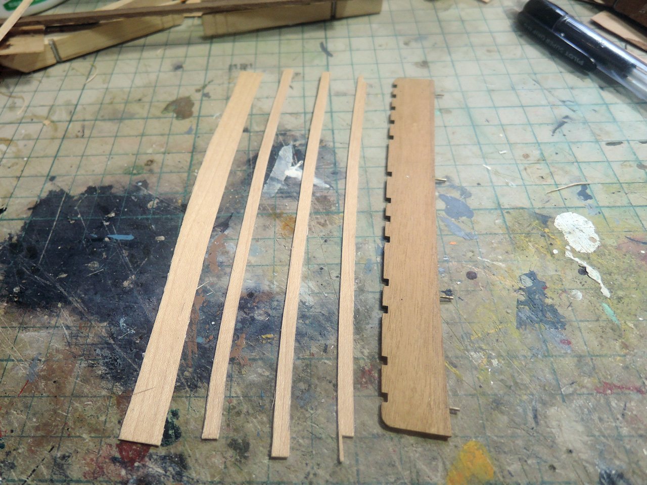
Both ends of kit channel parts were cut and thicker walnut pieces were glued instead. Then undersides of end pieces were tapered towards outboard as dummy effect of reduction of thickness of channel towards outboard.
As reinforcement of channels, diagonal iron bar PE parts are included in the kit like HMS Victory today in Portsmouth. It may be correct for Victory modernized with flash stern in 1803, but I felt it would be slightly modern method for ship of the line with open stern gallery. So I added knee on the channels. They were made from excessive 1.5 mm limewood in the kit.
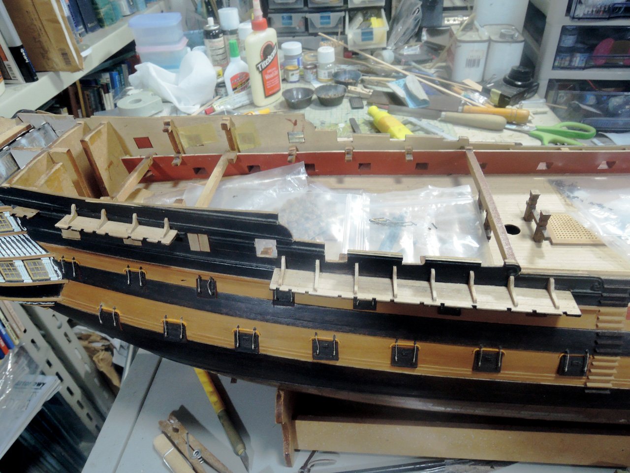
After glued with epoxy glue tightly, channels are blackened with black dye and ebony colour Watco oil.
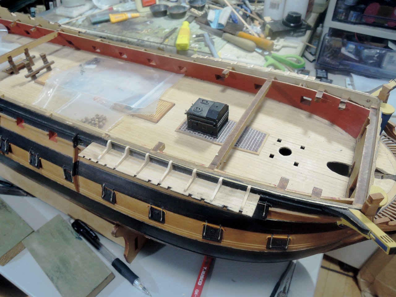
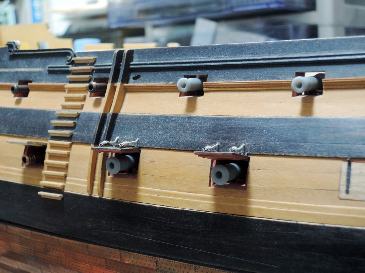
Guns were painted in black and temporary fitted to starboard only.
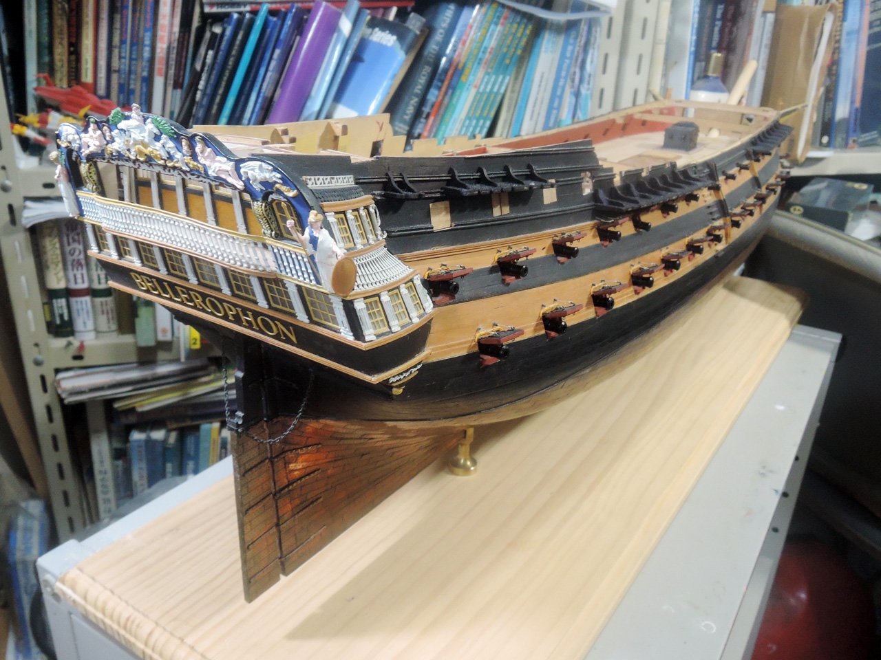
In this status, my model was displayed at annual exhibition of our club last year.
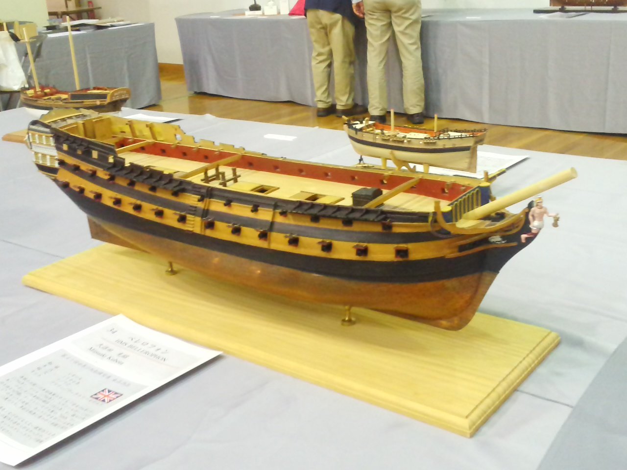
At link below, other images of my model at that time can be viewed with more excellent photography of our club member.
http://ysmc.la.coocan.jp/exhibition/ex2019/34.html
Next, I will post about deadeye chains.
- ccoyle, dkuehn, GrandpaPhil and 4 others
-
7
-
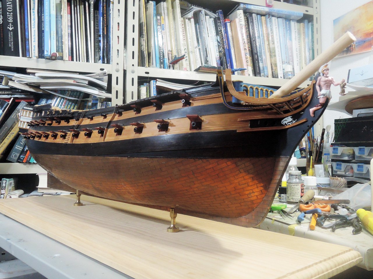
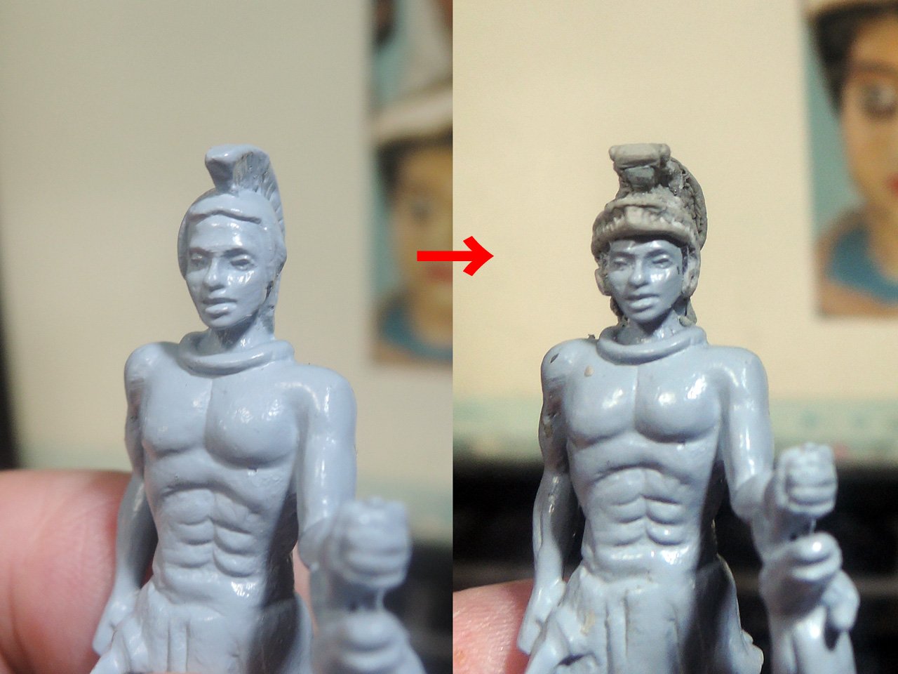
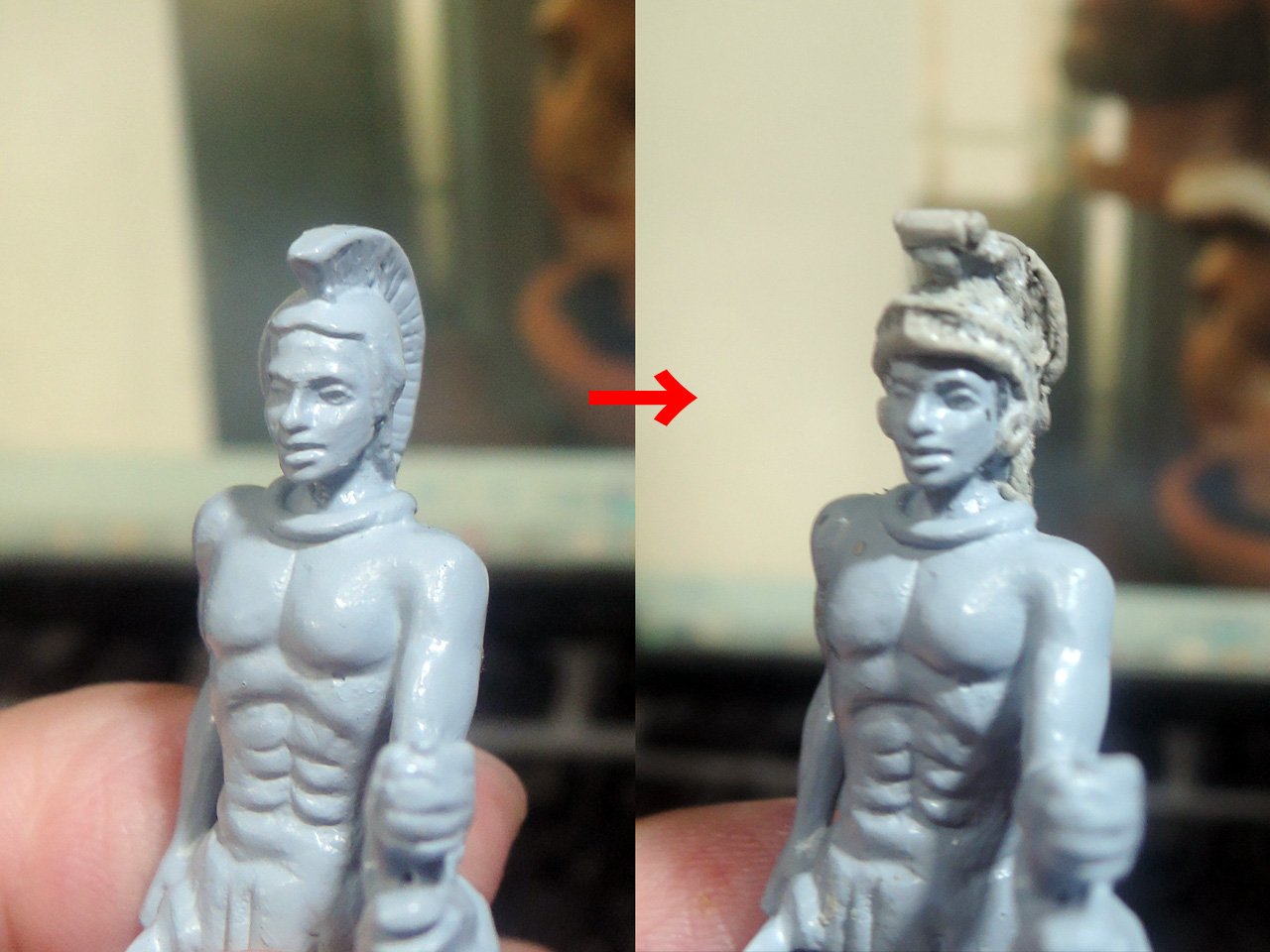
Figurehead
In Royal Naval Museum Portsmouth, remains head of figurehead which is said saved by Rear Admiral Maitland (former captain of Bellerophon and Napoleon surrender fame) when Bellerophon was dismantled.
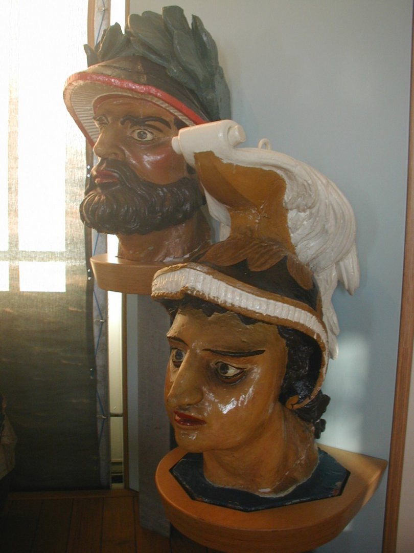
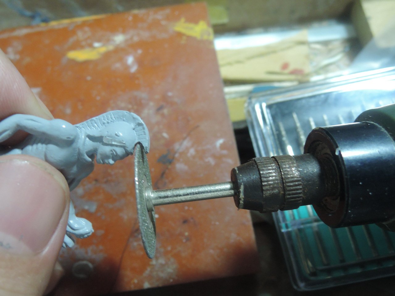
Although whole figurehead isn’t preserved, helmet of figurehead is different from kit part. So I tried improving it.
Kit figurehead part seems to be aluminium diecast and hard than white metal. But I could remove excessive portion of helmet with electric tool. Other details are formed with epoxy putty.
Next, I will post about channels.
-
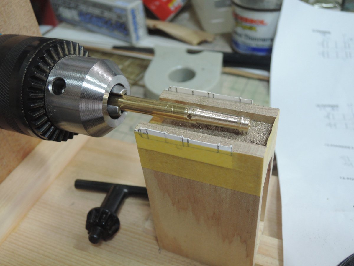
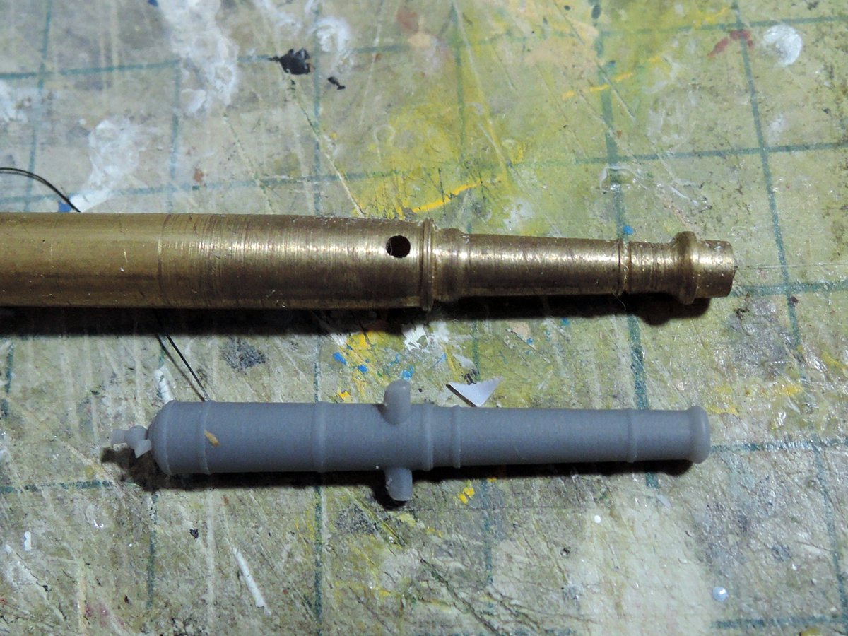
Gun barrels
One of my disappointments of the kit is size and shape of cannon barrels which are coming from stock store of Amati. They are smaller than they should be and muzzle shape is also bad comparing with many reference sources.
Best resolution should be turning brass rod and chemically blackening them, but my first attempt of turning with electric drill turned out to be sad result...
The advent of free 3D modelling software and 3D printing are gospel for me. Although the popular Fusion 360 was impossible to install to my PC (I’m still using 32bit PC), free software called DS Mechanical worked enough instead of Fusion 360.
After some trial and error, data of barrels is completed. They are basically simple design to turn section 360 degree and adding trunnion, breech ring and vent field.
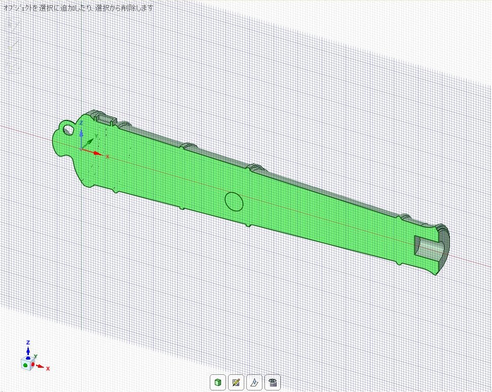
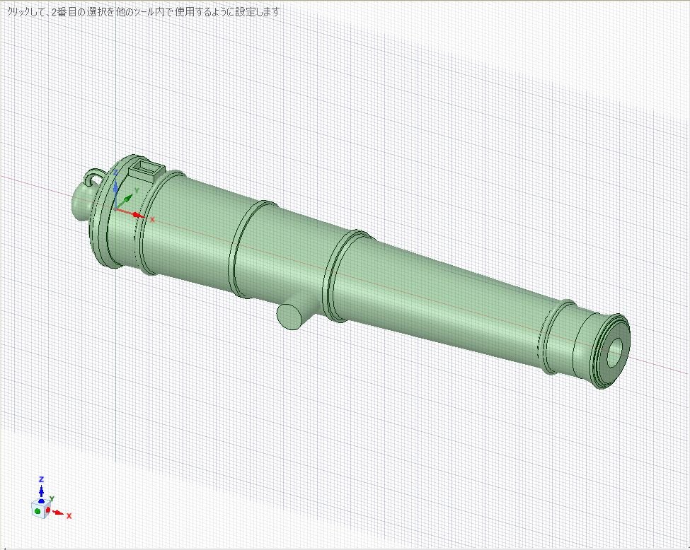
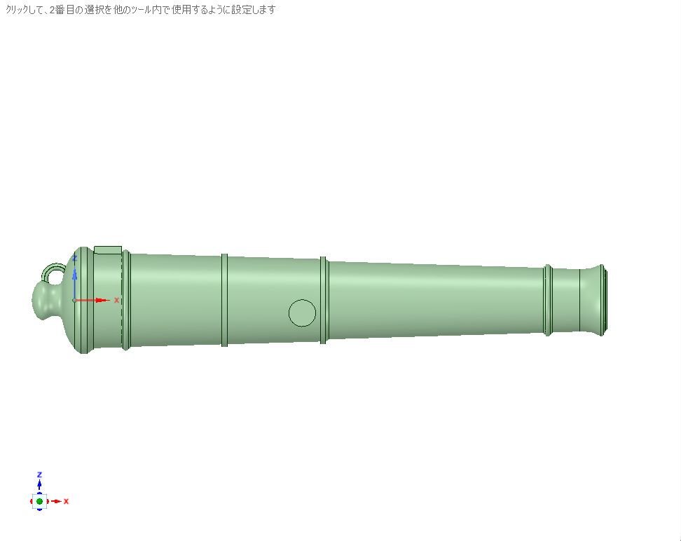
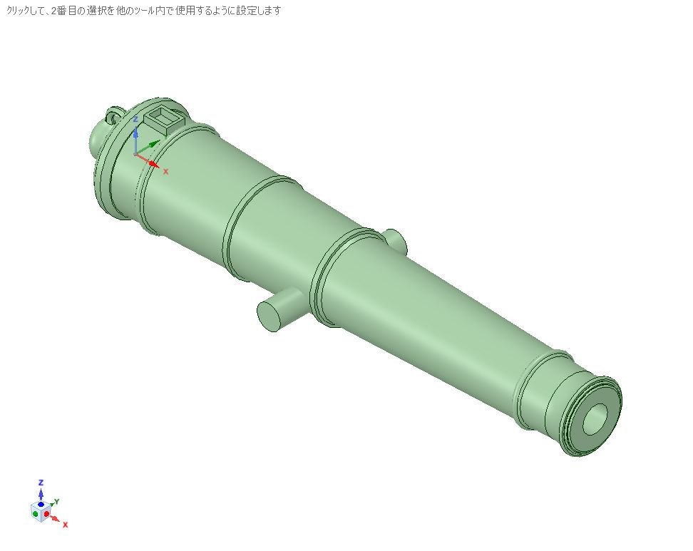
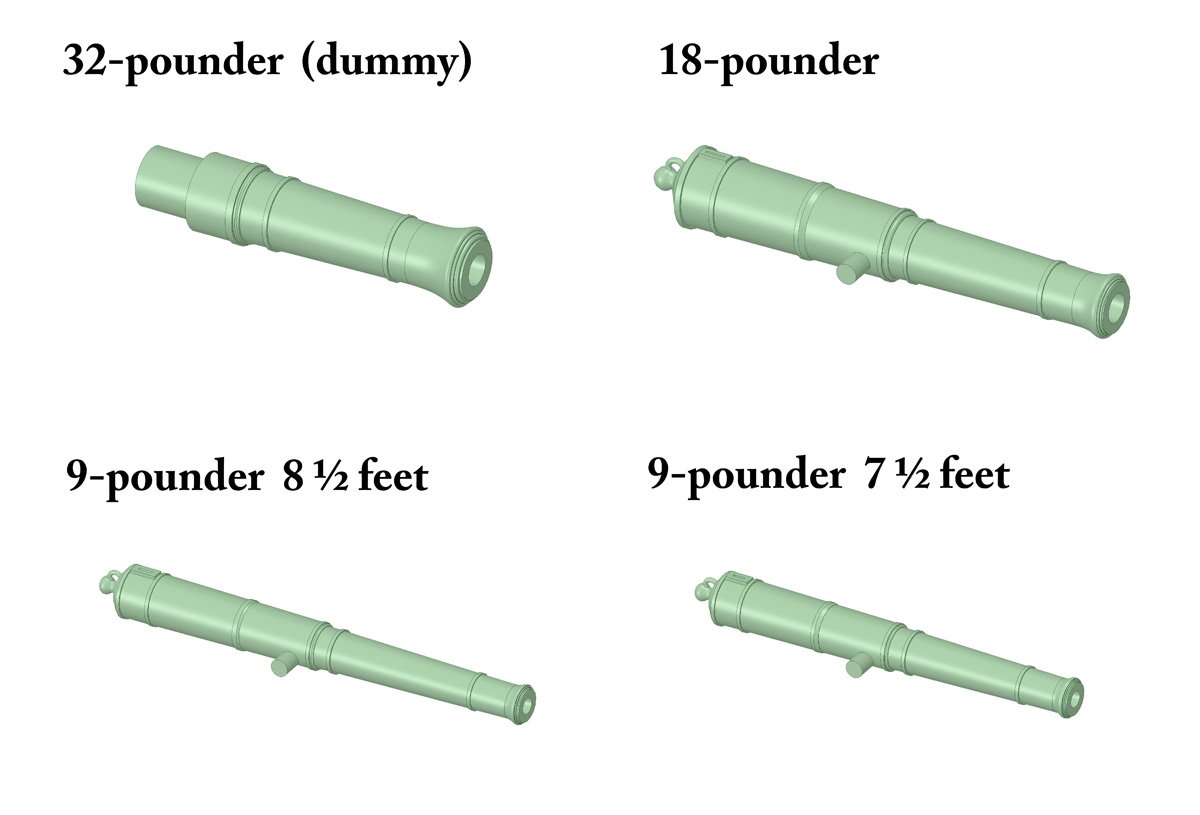
Sizes are slightly different by info sources, but this time I’m relied on AOTS Bellona.
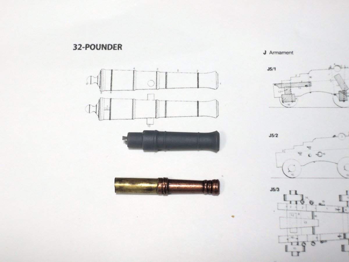
Printing is next subject. I firstly asked 3D printing agency, but printing each barrels one by one is very costly. At that time I didn’t have technique of multiplying of data to print at once. Fortunately one of my fellow modeller who is producing some nice 3D printing kit (including HMS Furious as she was firstly designed with two 18 inch single guns) printed barrels by his courtesy. Bellow is his shop URL.
https://flotilla-models.booth.pm/
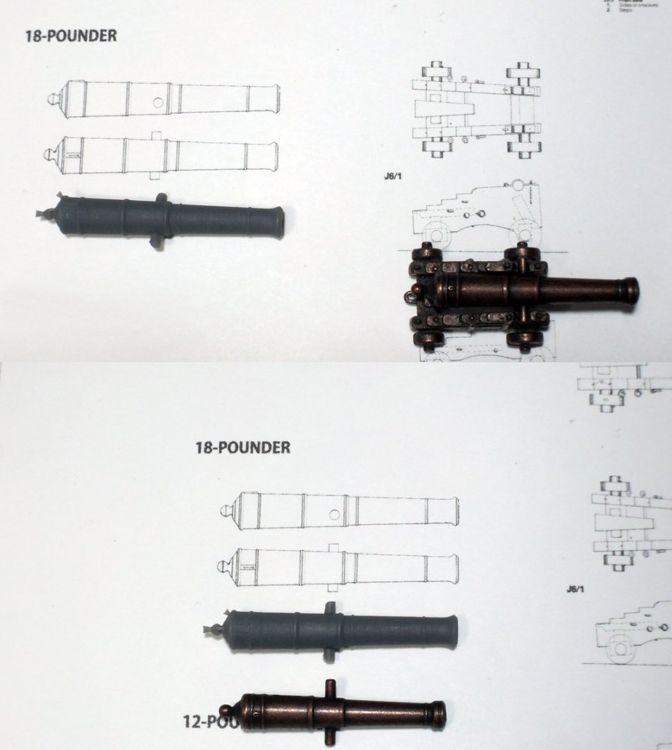
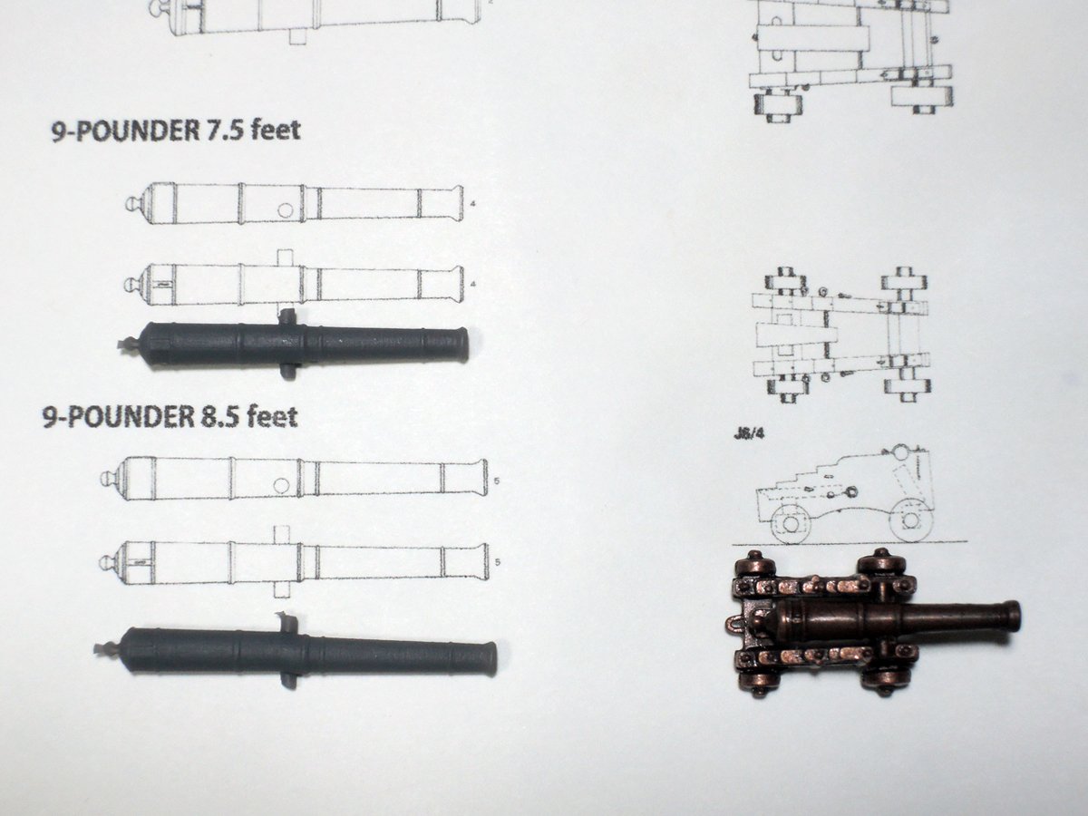
Bellows are comparing of 3D gun barrels with kit part and my first attempting of turning.
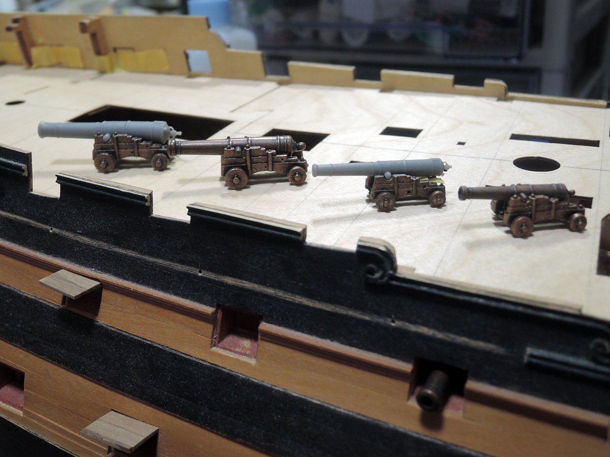
Test fitting of guns on decks.
Next, I will post about figurehead improvement.
-
-
Daily life and other modelling projects had been preventing me from building of Bellerophon, but some progress has been achieved while I had been offline from this forum. Bellow is records of how I made gunport lids, gun barrels, channels and chains.
At the re-start of my building log, I’m going to write about gunport lids firstly.
Gunport lids
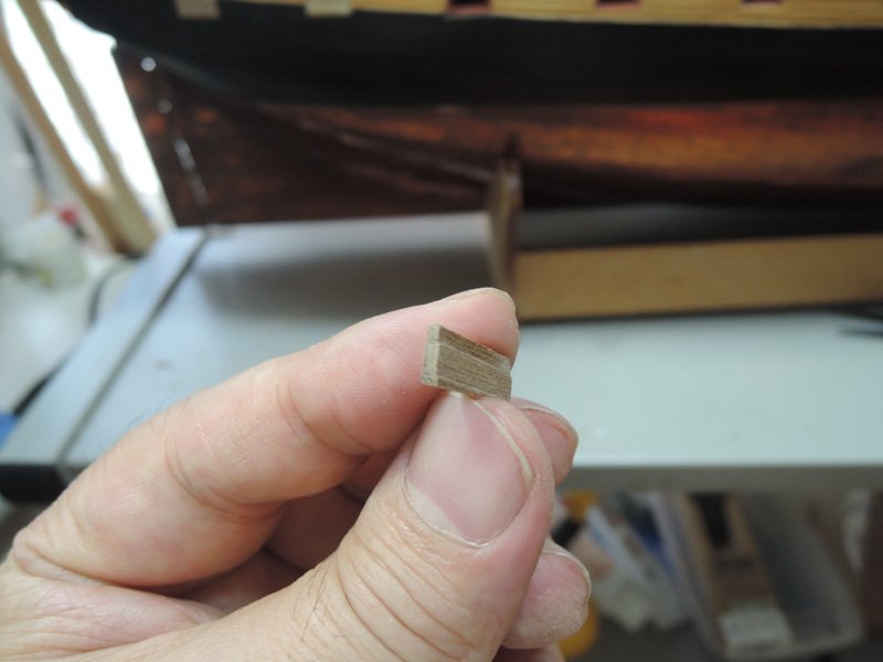
Gunport lids were individually made because they have different sections according to their position and running of wale. I firstly cut backing of lid from 0.5mm maple sheet and glue outer panel of 1 x 5mm walnut strip including in the kit. Walnut strips were laid so that they are fitting to running of planking.
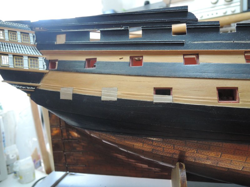
Some of lids are covering area of wale. They were made from thicker walnut material and also shaped so that each of their section is fitting to running of wale.
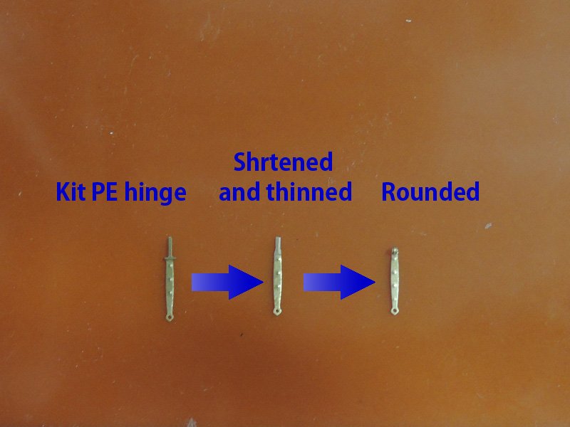
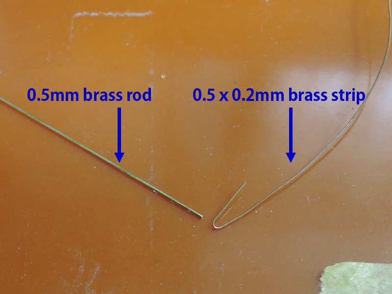
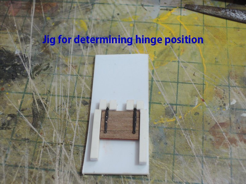
Lid hinges are modified from kit PE parts. I’m sorry I’ve forgotten whose idea it was, but I remember this is idea I found on this forum. I modified kit PE hinge to workable as he did. Peak of kit PE hinge are shortened, thinned and rounded. Pintles are made from 0.5 mm brass rod and 0.5 x 0.2 mm brass strip.
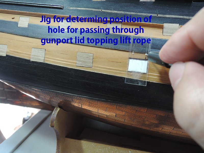
Position of each hinge is determined with jig. Position of hole to pass through lid topping lift rope is also determined with jig.
Home-made rings are added to inside of each lid. Passing kit eyebolt through lid from outside, then bend the other end of eyebolt to grab home-made ring.
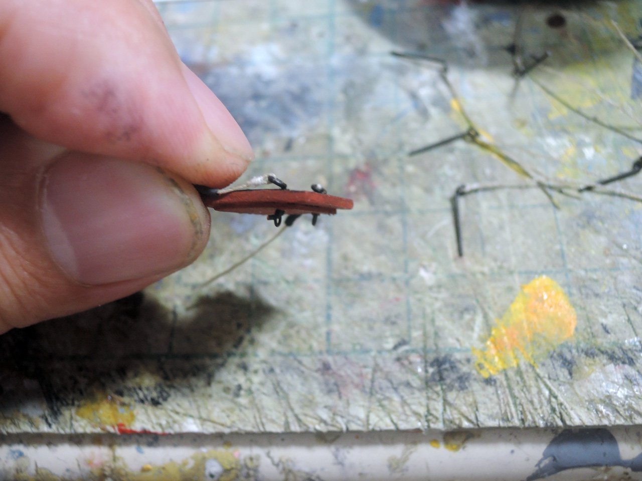

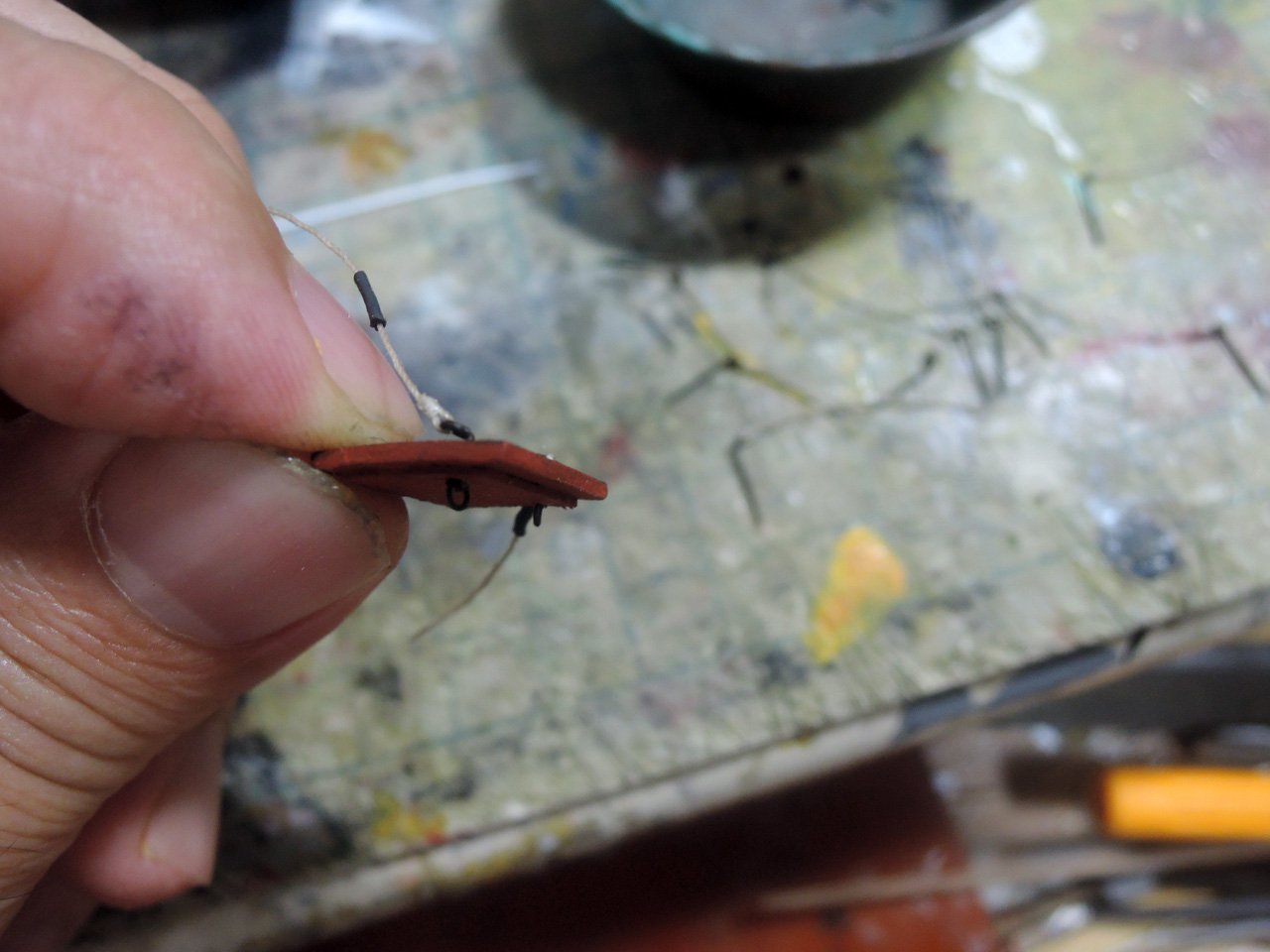
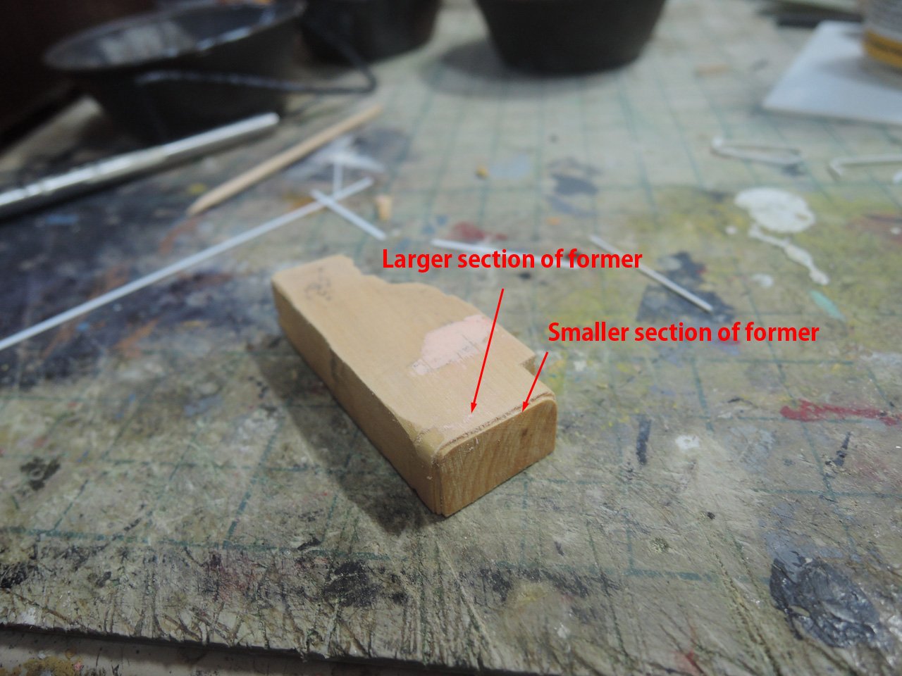
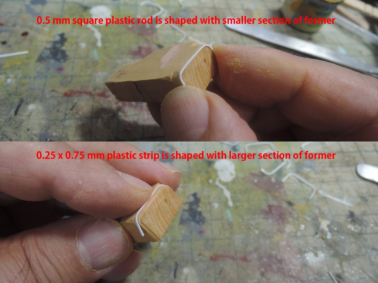
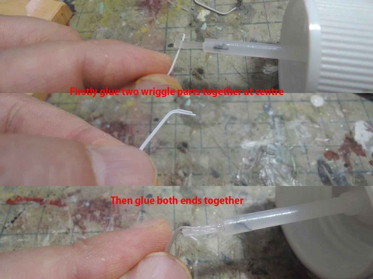
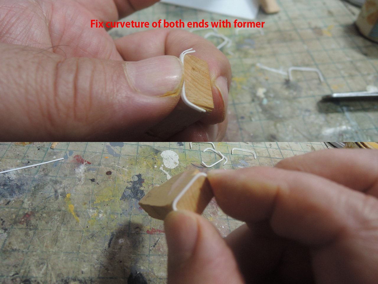
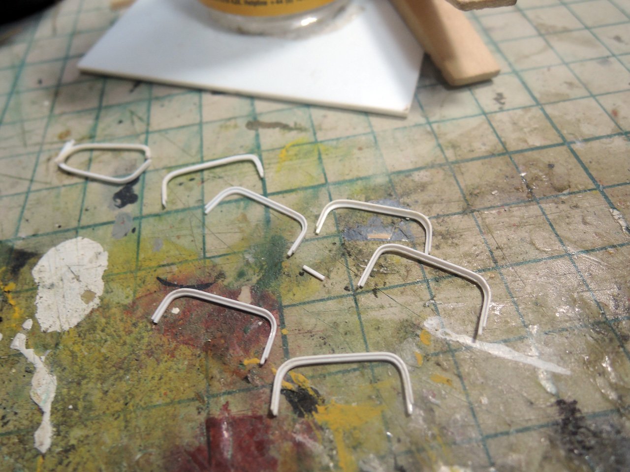
Gunport wriggles are made from 0.5 mm plastic square rod and 0.25 x 0.75 mm plastic strip. My method of making wriggle was inspired by Mr. Philip Reed’s book treating HMS Majestic. Mr. Reed firstly made outer section of wriggle then reduced size of former and made inner section of wriggle, but I prepared former integrating both of larger and smaller section.
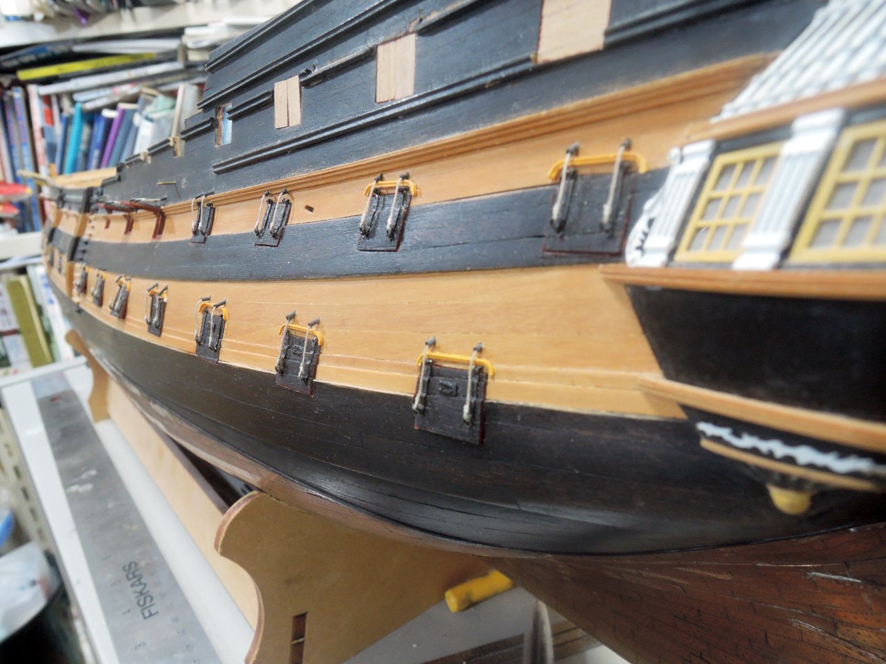
Covering of lid topping lift hole is made from heat shrink tube. Also I’m sorry I’ve forgotten who is the man firstly posted this idea, but I’m satisfied with its result.
Next I will write about gun barrels.
- mtaylor, bruce d, GrandpaPhil and 2 others
-
5
-
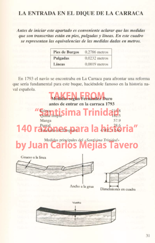
Maybe this is not from period you are interested in, but I found spar dimensions table of Santisima Trinidad of 140 guns.

But in my humble opinion, if you found fortunately old Spanish source, great care would be required when using them because they may be recorded in "Pie castellano" or "pie de Burgos" which is shorter than international foot which is familiar todays.
"Pie castellano" namely "Castilian foot" is old unit used in Spain until 19th century and 1 Pie castellano equals to approximately 278.6mm.
https://es.wikipedia.org/wiki/Pie_castellano
I think dimension above is described in Pie castellano or pie de Burgos. Actually other page from same book shows clearly length of "Pies de Burgos".
Hope these helps,
-
On 7/10/2019 at 8:40 PM, jock2000 said:
Started on some small bits with PE. I don’t know what this is and can’t find a reference, maybe someone can help.
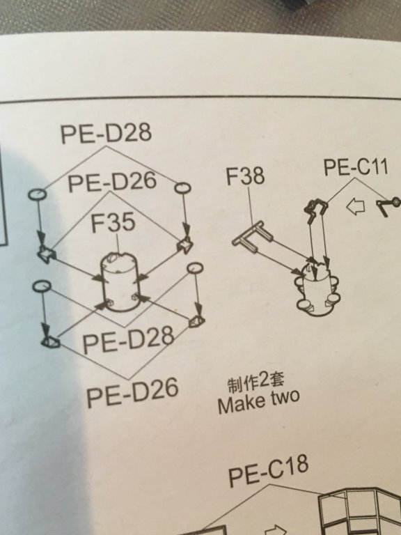
Hello Jock2000,
The object you are asking seems to be "Pom pom gun director".
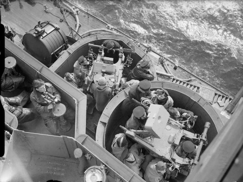
I found Trumpeter kit instruction by chance(https://issuu.com/modeland/docs/03709), and instruction shows the object to be glued corner of "director control tower platform".
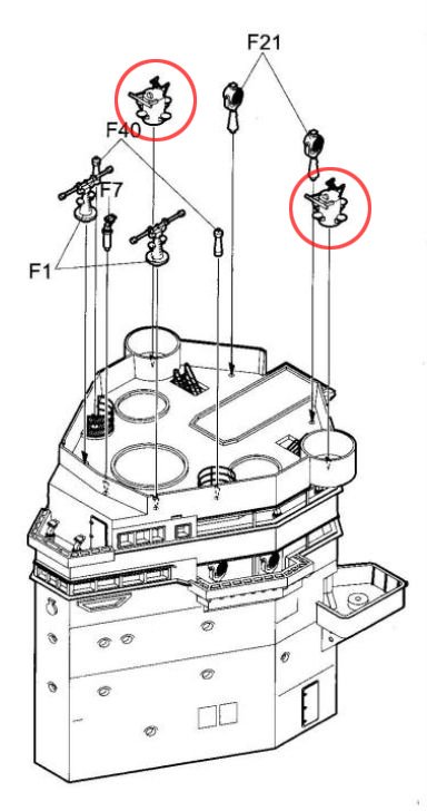
But I believe there should be single 20mm Oerlikon MG in this position when she adopted atructive camouflage.
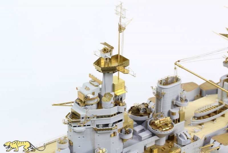
Above image is from Pontos grade up set.
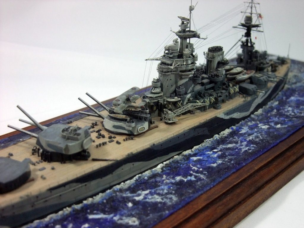
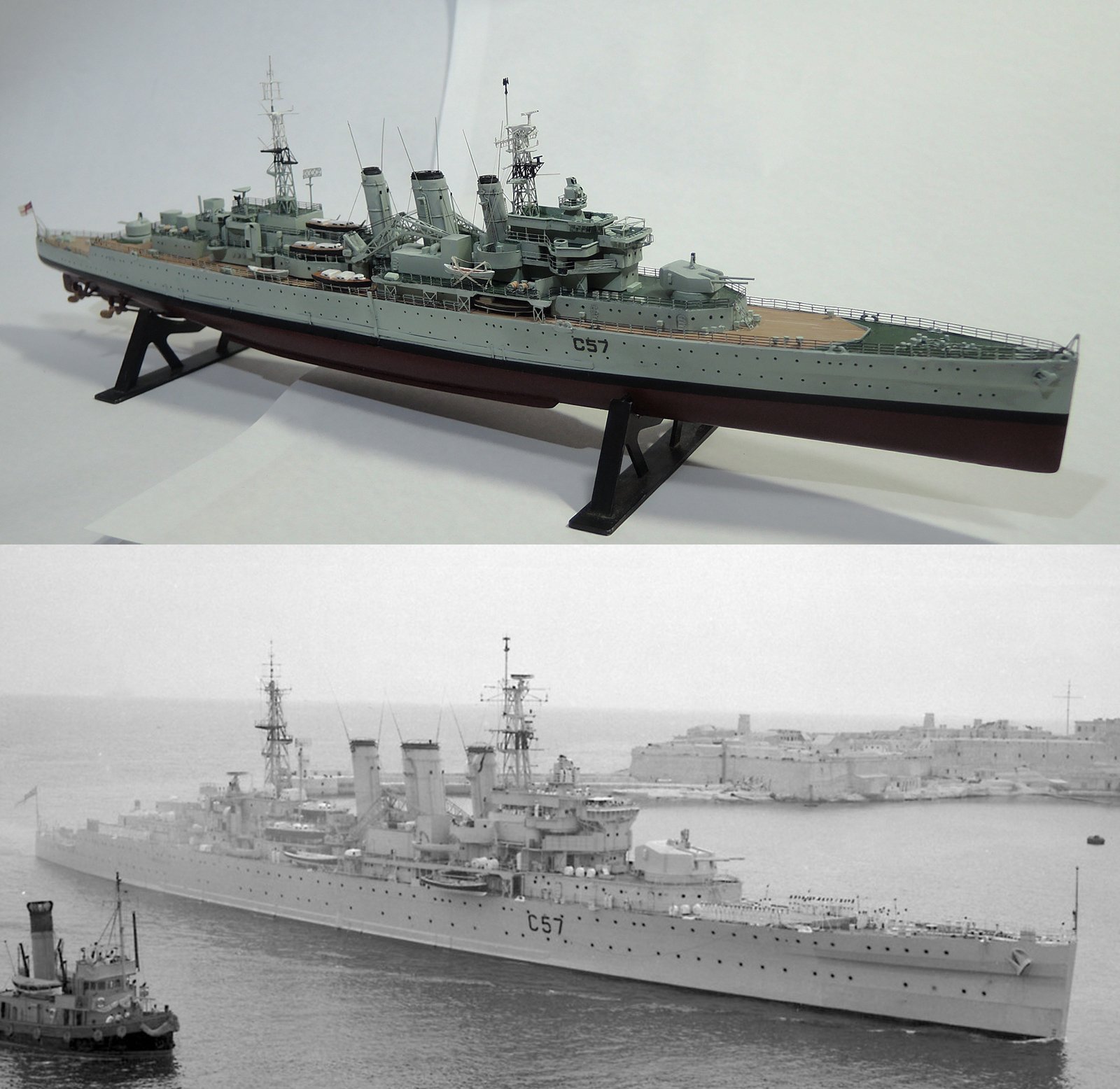
And my 1/700 model of Rodney(https://photos.google.com/share/AF1QipNVs5uetAQMQkkC2WQZiGWTZbEHBS4RZXcPzqHA1inJubKjROC32A-155Dr_oe0ZQ?key=eHlrY1pHSEwweEUtZHB3azNlU0VHY2p0N3Nodzl3).
Unfortunately Trumpeter kit seems to be "chimera" from different time frame of Rodney. For example painting instruction shows her 1942 camouflage pattern, and "most of" AA gun positions seems to be right in her 1942 configuration. OTOH, kit PE parts for radar on both mast peak seems to be Type 279, but they should be Type 281 in 1942.
Also Trumpeter kit shows quadruple 0.5"MG on aft corner of bridge structure. They are right for her earlier war years, but this should be replaced pom pom derector with Type 282 radar. Below is instruction from Tom's Modelworks 1/700 PE set and shows these alternation.
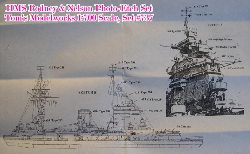
Of course this is your model, and you have privilege to decide how to build your model. But still I hope my info of above would be help for you.
Regards,
Mitsuaki
- Dubz, coxswain, popeye the sailor and 7 others
-
10
-
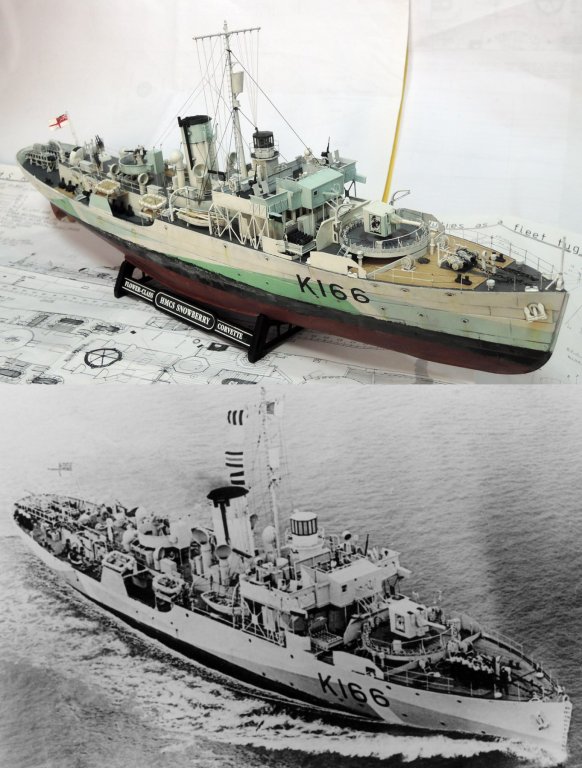
James,
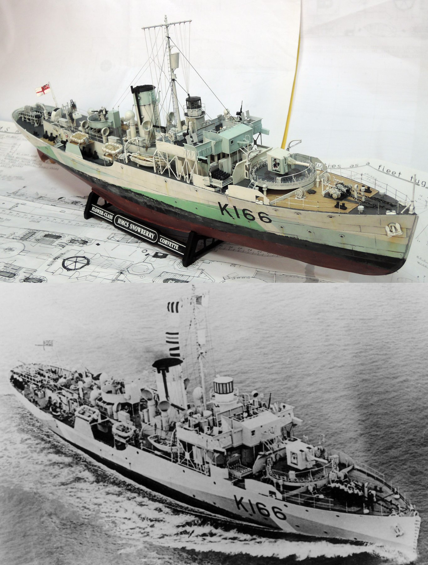
It is very coincident because I also went to Shizuoka three weeks ago with my Snowberry!
BTW, I gathered my tweets on building records of Snowberry.
Although all texts written in Japanese, English captions on images will help to understand how I modified the Revell 1/144 kit. Although auto English translation isn't perfect, it also help your understanding.
https://togetter.com/li/1194066
Bob,
Congratulation to completion of your Vanguard. I started my Bellerophon about a decade ago, but still requiring to finish hull fittings

I will refer your rigging when I start rigging my model

-
Hello James,
Thank you for salvaging my topic from bottom of the thread list!
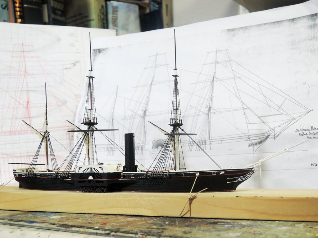
Daily life, work and other projects have been preventing me from proceeding the Bellerophon, but I hope I will soon restart her after finishing 1/400 miniature model of US side wheel steamer Powhatan. This model is being built as part of diorama of Commodore Perry's second expedition to Japan. The diorama will be exhibited at Yokohama Sailingship Modelers Club exhibition which will be held coming September.
Regards,

-
Hello Bob and John,
Thank you for your comments

Bob, thank you for your warning on mast construction, though It will take some months (or many years
 ) for me till I go into mast construction. It is very appreciate to avoid possible error from others' experience. Also reading discussion between you and Len, I again realized the importance to read instructions.
BTW, I'm preparing for presentation at seminar of Yokohama Sailingship Modelers Club of next month and writing resume now. (http://ysmc-world.la.coocan.jp/event/kenkyuukai.html)
Of course I will include introducing our forum to club members in my presentation. I really hope both of forum members and club members enjoying our contents each other.
Regards,
- mtaylor, dafi and freewheelinguy
-
3
-
Hello ZyXuz, Bob and Len,
Thank you for your kind words
I really realise this is a great place to share our knowledge and experience each other. I myself study many things from other member as I noted time to time.To Bob,
Yes, you are exactly right about interpretation on my coppering procedure. If copper plates have nails represented by "stamp" as can be seen on many kits from other manufactures, it would cause some problem when overlapping them. But copper plates included in Victory Models kits are photo-etched ones and have no protrusion on their surface, so overlapping of plates doesn't cause any problem.
I separated all copper plates. Perhaps unseparated plates would fit well only to keel and garboard strake because of fuller hull shape of wooden warships, although I maybe try fitting unseparated rows in the case of clipper ship
Hope these helps.
Kindest regards,
-
Hello druxey,
Thank you for your kind word
Before starting of head construction, it was very anxious matter to finish head successfully. But careful procedure resolved everything. Especially template for cathead bracket was the key to successful result.
Regards,
-
Hello Jason, Guido54, Ray, Aldo and Alan,
Thank you for kind words
BTW, the model was displayed at exhibition of Yokohama Sailing-Ship Modelers Club of this spring. Bellow is link to gallery page of the exhibition. Please enjoy beautiful works of the club members. Of course my model is also included in the list.
http://ysmc-world.la.coocan.jp/exhibition/ex2013/ex2013.html
Regards,
-
Hello Mio, Richard, Daniel, Arthur, Dirk and Juergen,
Thank you for your comments
Perhaps Arthur remember that I'm now working at workshop for deaf people. We are doing small assemblies like pencils, pencil lead sharpeners or paper clops. I sometimes make jigs for those assemblies and it is great joy to see my jigs help deaf people to assemble products easier and faster. Old people said that “Art brings cheese”. Perhaps modelling skill can be said as one of “Art”. Actually skill cultivated by modelling helps me a lot on the job.
Regards,
-
Hello B.E.
Thank you for your kind word
Although decorations of late 18c ships is surely simpler than those of previous years, they still show very beautiful appearance beside with gentle curve of basic structure of head, quarter and stern galleries. I really like them.
Regards,
-
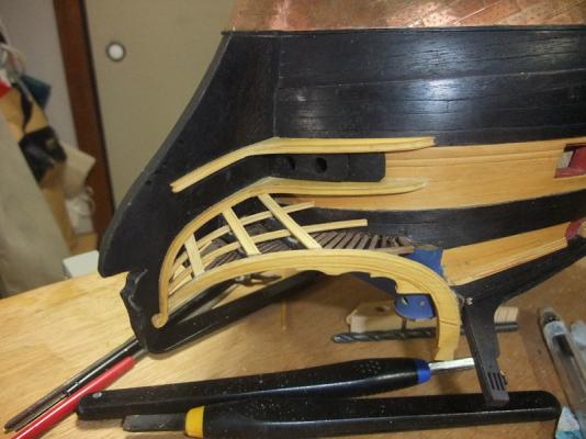
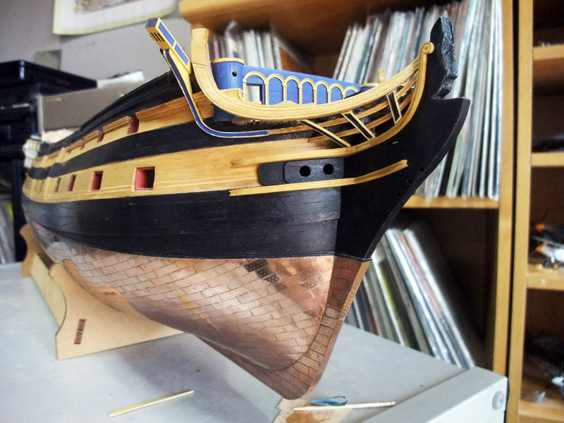
Completion of head
I managed head construction as depicted above. I’m thinking result is not bad and feeling relieved to finish this difficult section.

Photos above are of close-up of bow rails. BTW vertical sections of beakhead balkhead columns (part 418) are replaced by Evergreen channel strip because moulding direction of kit photo etched part is inverted.
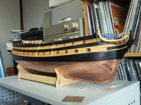
Photo above is showing entire model.
These are all I can upload now. I'm now preparing guns for the model. I really hope members enjoy my building log

Regards,
-
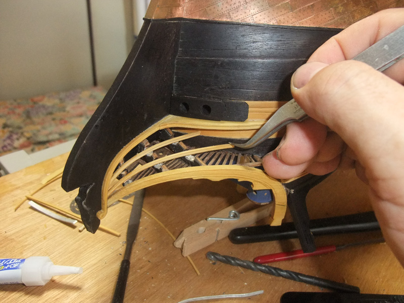
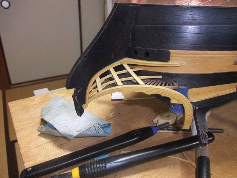
Cathead support
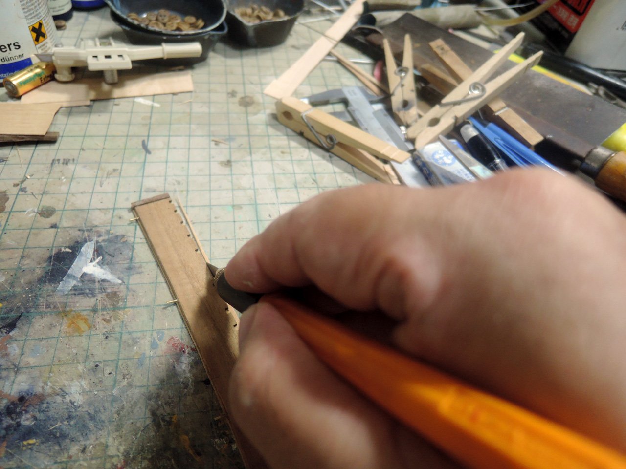
Cathead support is one of most difficult parts to determine its shape. Not only its own graceful and complex 3 dimensional curve it should also fit on bow flare with minimum gap. Photo above is of pattern cut from black card.
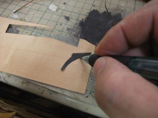
transferring of outline from pattern to 0.5 mm maple sheet.

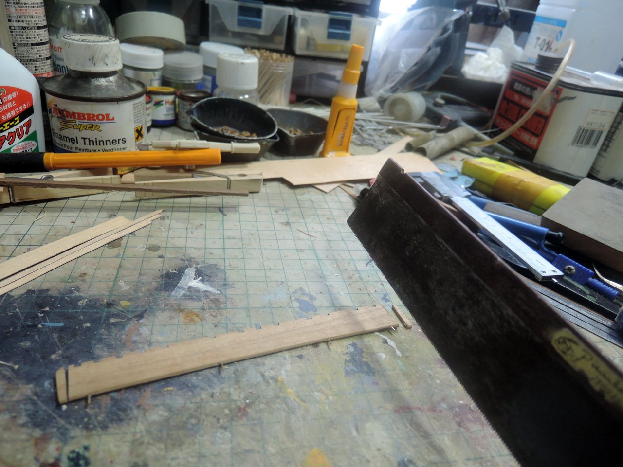
Maple sheet is cut following pencil line transferred from pattern.
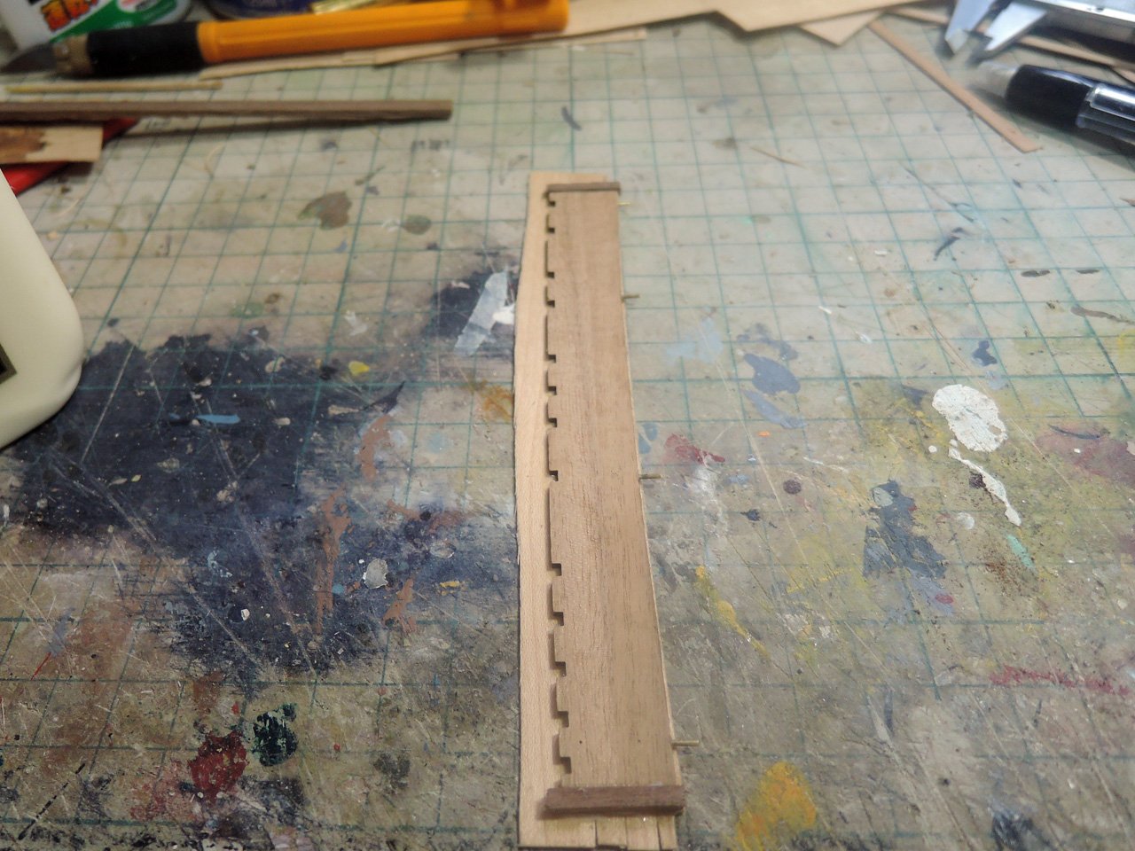
2mm walnut piece is sandwiched by maple. Lower section between two maple sheets is also filled with walnut piece.
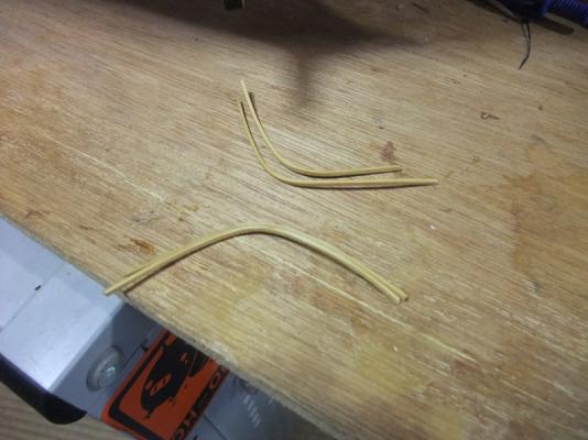
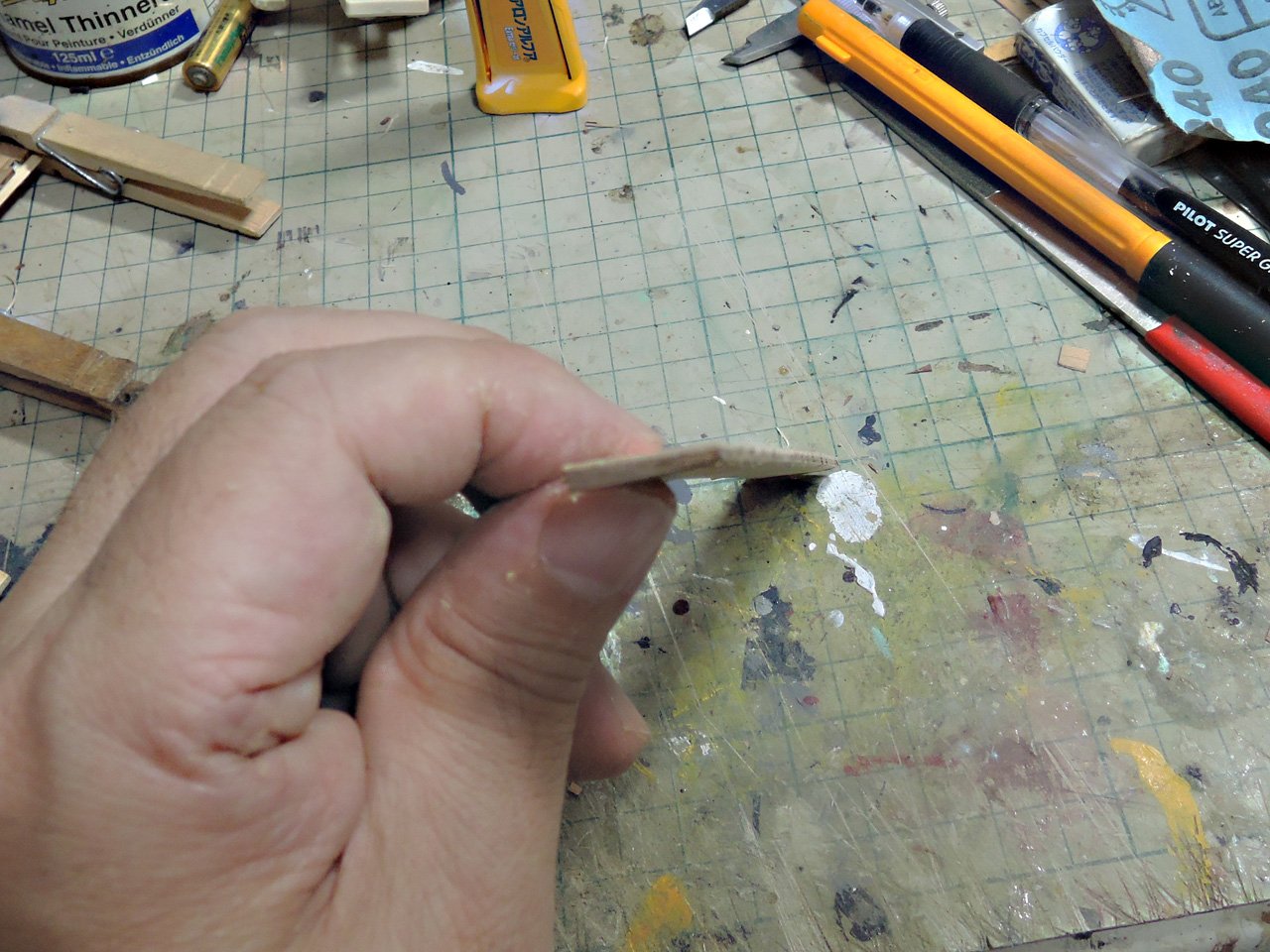
Rail connecting cathead support and middle head rail was built from pair of 1 X 1mm strip. It is far easier to bend pair of 1 X 1mm strip than 2 X 1mm strip. Bent them with steam and heat from kettle, then after desirable curves were gained, the pair of strips is glued together.

Photo above is showing connection between middle head rail and cathead support on its position. It was moulded with metal edge pattern and cut to appropriate length and glued to its position.
- Blue Ensign, druxey, freewheelinguy and 3 others
-
6
-
Continuing of head construction
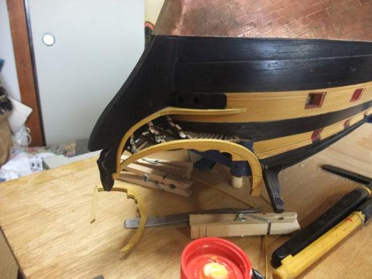
Photo above is of gluing of upper rail.
Middle and lower rails are installed. These rails are 2 X 1mm amarillo strip and bent with steam and heat from kettle. I also add moulds to them with metal edge pattern.
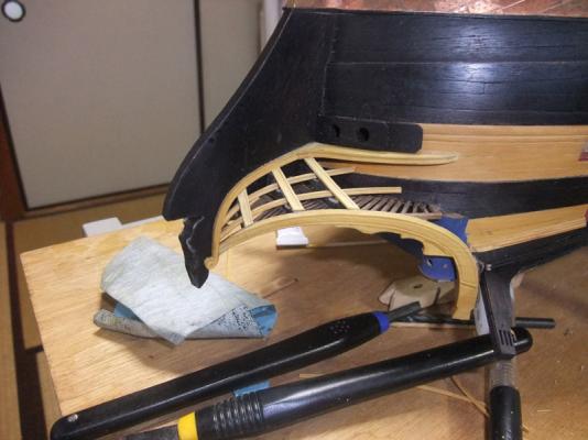
Photo above is of covering to V shaped timbers. They are 3 X 1mm amarillo strips. I add some moulds to these covering strips as shown on pictures.
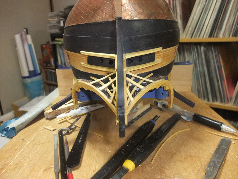
Installation of lower cheek
Symmetry of both sides are checked from directory forward. Perhaps small asymmetry would be discovered by careful examination, but I’m satisfied with the results.
Photo above is showing painting of catheads. Blue areas are represented by gluing thin strip shaved from amarillo and painted in blue.

- mort stoll, dafi, druxey and 2 others
-
5


HMS Bellerophon 1786 by fake johnbull - Amati/Victory Models - 1/72
in - Kit build logs for subjects built from 1751 - 1800
Posted
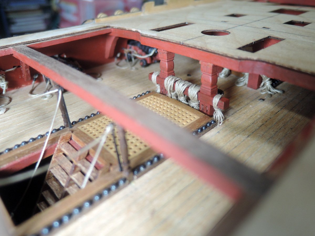
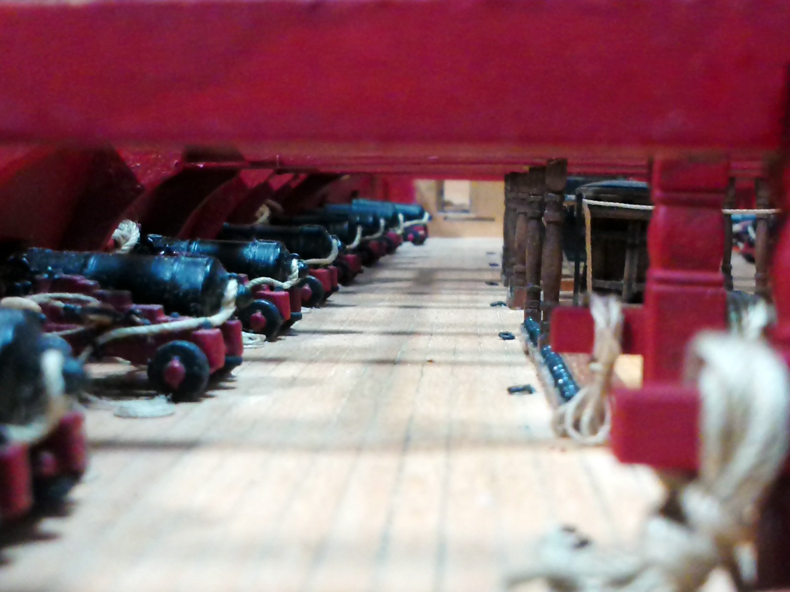
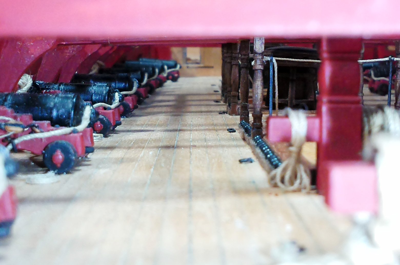
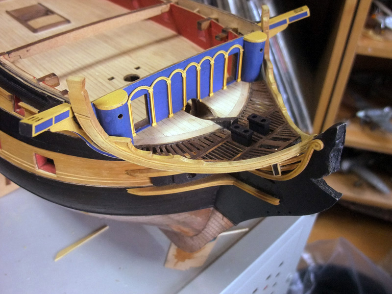
Thank you for your comment.
Some more images seen from beakhead bulkhead opening.