


Hubac's Historian
-
Posts
3,220 -
Joined
-
Last visited
Content Type
Profiles
Forums
Gallery
Events
Posts posted by Hubac's Historian
-
-
-
-
Voila!
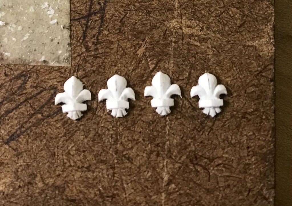
These are now clean and uniform enough to mount and make mould impressions from. And then, I’ll just be making a ton of em!
- yancovitch, mtaylor, hexnut and 4 others
-
 7
7
-
Well, it was a delightful week away, spent entirely on the beach. I didn’t get to any of the carving I thought I was going to do, though, but that is just as well; I needed a break from everything.
Today, I carved the first of four fleur-de-lis that will make up my master for the frieze, and probably the lower battery port lids, as well. And maybe even the middle battery ports, if they don’t seem too large.
Here’s what that looks like:
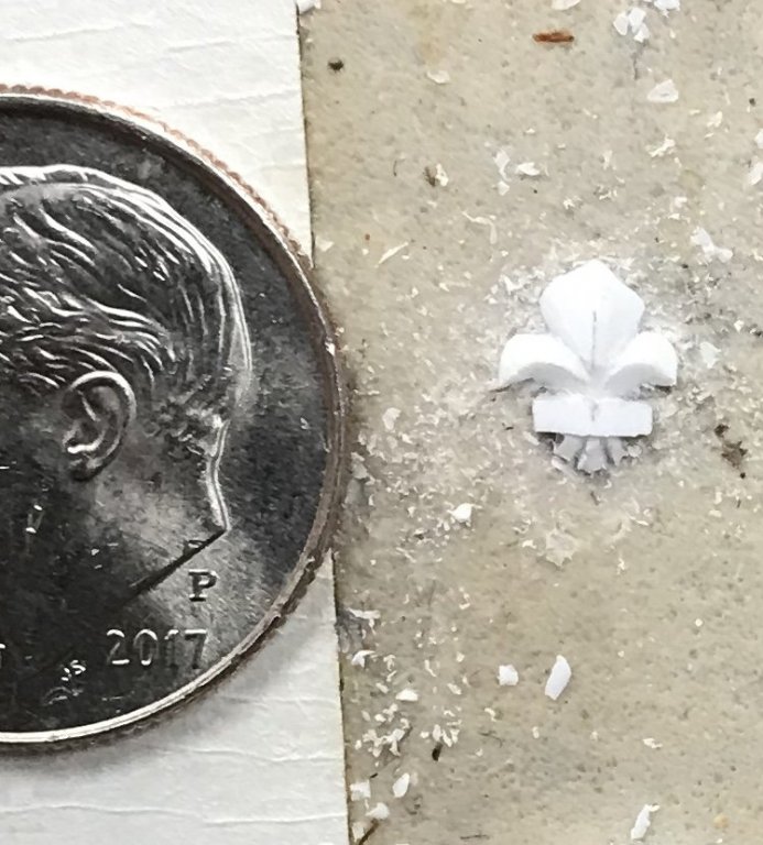
And one more shot against a clear ground:
If they all come out at least this well, I will be happy.
-
The figures of the four seasons really tie the whole thing together, EJ. These are your best carvings, yet!
-
One of several aspects of your Licorne build log that has been especially helpful to me, Mark, is the galley stove section of your build. I’m not sure I will go whole-hog and build a full galley stove, like you did, but I will probably include the visible portion, beneath the f’ocsle deck, as well as the chimney through the deck. This was a detail I was aware of, before, but your particular approach made it seem very doable to me, and worth the extra effort.
-
You are welcome, Jay. In truth, though, I owe my understanding of the allegory of SR’s stern to Michel Saunier and his painstaking research for his completely scratch-built model. Michel is the primary researcher of this ship. If you haven’t seen his model, you should look it up on MSW.
-
-
In preparation for my week off, in Cape Cod, I am trying to prepare fleur-de-lis carving blanks for the frieze. My current inability to print my GIMP drawing, to scale (or at all, really), has me improvising in ways that are somewhat successful and in other ways not.
I’ve been taking measurements off my flat computer screen with my Starrett rule, to determine that my fleur-de-lis for the frieze should be very nearly 3/16” x 3/16”. Great, I think to myself - I have styrene strip that is 3/16” x 1/16” thick!
So, on a piece of vellum, and within these perameters, I begin to attempt drawing my fleur-de-lis. This takes a few hours to arrive at proportions that are pleasing and approximately close to what I could achieve on the computer.
For reference, though, I went back to pics from a recent visit to the Met, which featured an exhibit on the court of Louis XIV. Among the exquisite items and artifacts, on display, was this relatively small marble study, that depicts Benjamin Franklin and Louis XVI, on March 20, 1778, signing the Treaty of Alliance. Aside from a relationship that would help (tremendously!) forge our American independence, what I was most drawn to were the perfectly rendered fleur-de-lis that adorn Louis’s cape. Look, Ben’s going in for the Bro-shake:
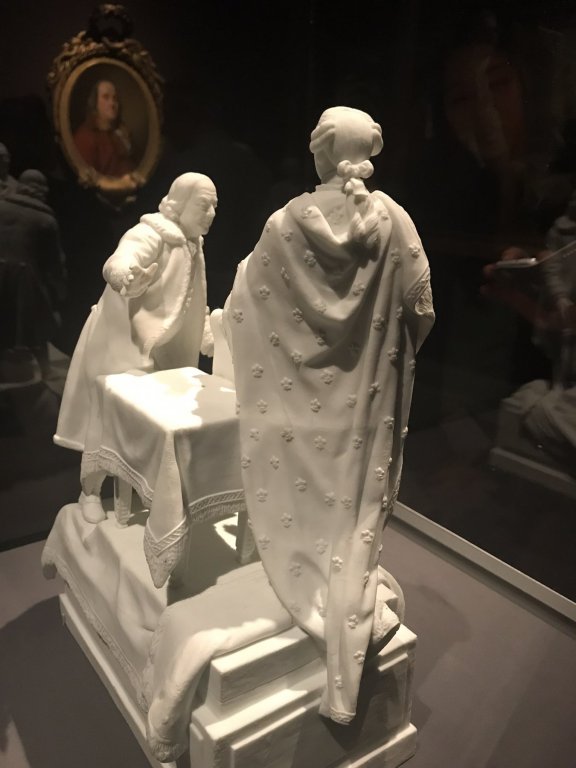
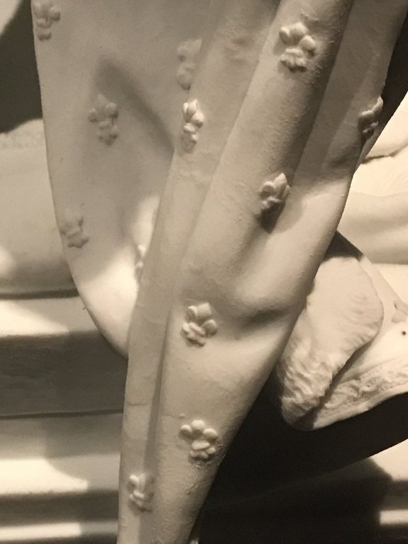
This is, in actuality, a very small-scale sculpture of this event in Amero/Franco history, but the carving of the marble is remarkable in its detail and consistency. Here, it seemed to me, was a perfect example of everything a fleur-de-lis should be.
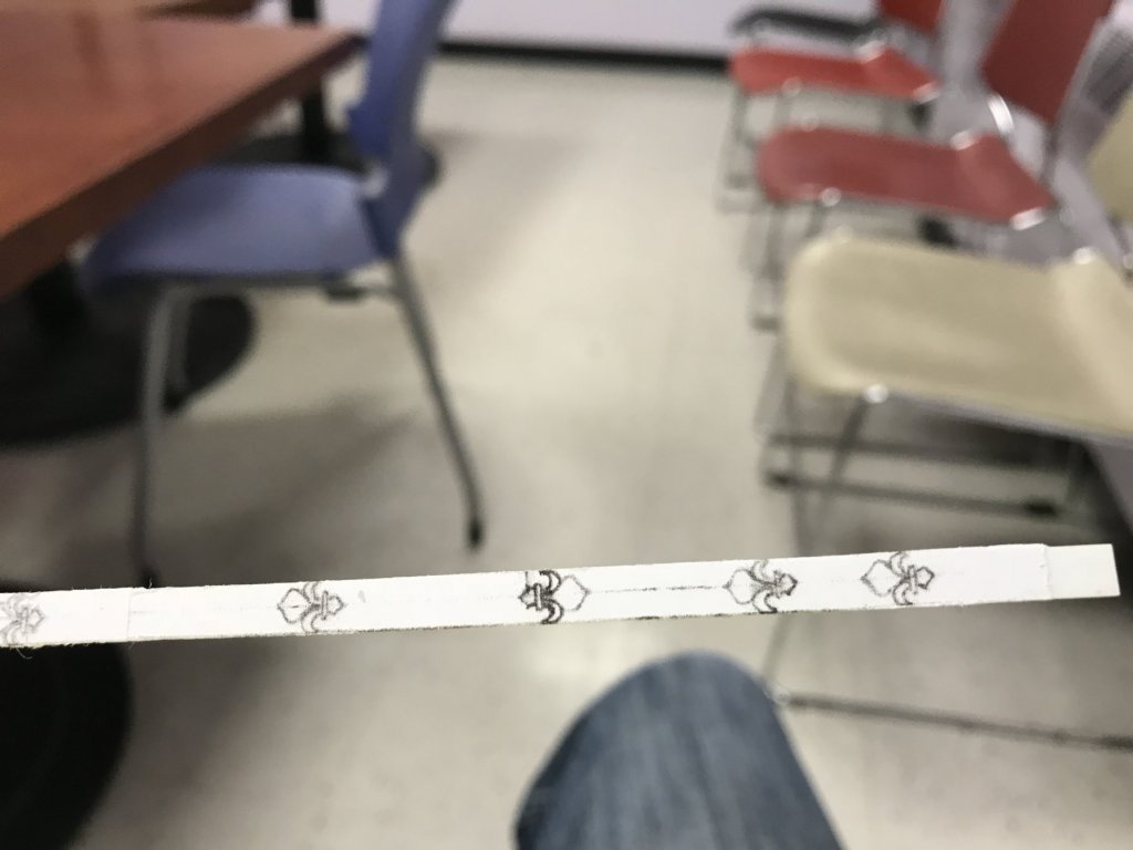
With that settled and the first flower drawn, I next folded the vellum over that first drawing, and made a series of tracings, all in a row - 8 in all. My objective, ultimately, is to make carving blanks from the five best tracings.
Reasonably satisfied, and reasoning as always, that I can correct shaping discrepancies with the tools, I pasted a photocopy of my drawing to a strip of styrene. I wanted to preserve the original drawing for the several other sizes of fleur-de-lis that I will need elsewhere on the ship.
Here is a photo montage of my mixed results and several epiphanies along the way:
These look decent. Workable. After filing a few to profile, though, I discovered that they did not fit neatly within the sheer strakes at the fo’csle and quarter deck levels, as I had previously drawn.
Keeping them, at this size, would necessitate letting them into the sheer strakes at these most narrow points. While this was an acceptable accomodation to me for the upper arches of the domed port enhancements, along the main deck level, I feel that this will not look passably ok with an ornament that would, naturally, be scaled to fit the available space.
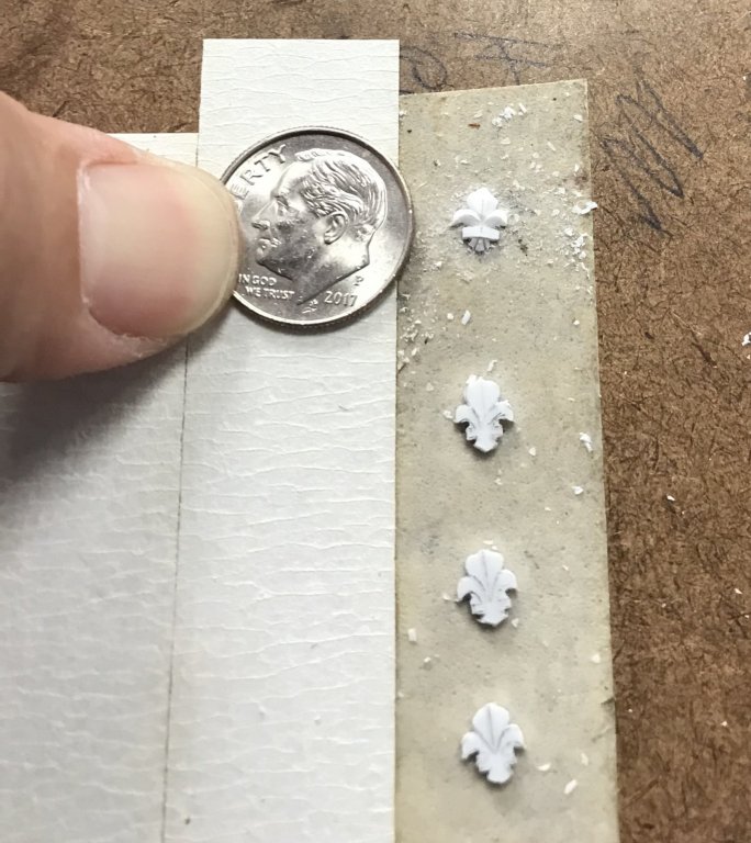
The middle fronds of the fleurs are small enough as it is. So, I decided to chop the points from the top and bottom of the flower until they, at least, fit within the sheer strakes.
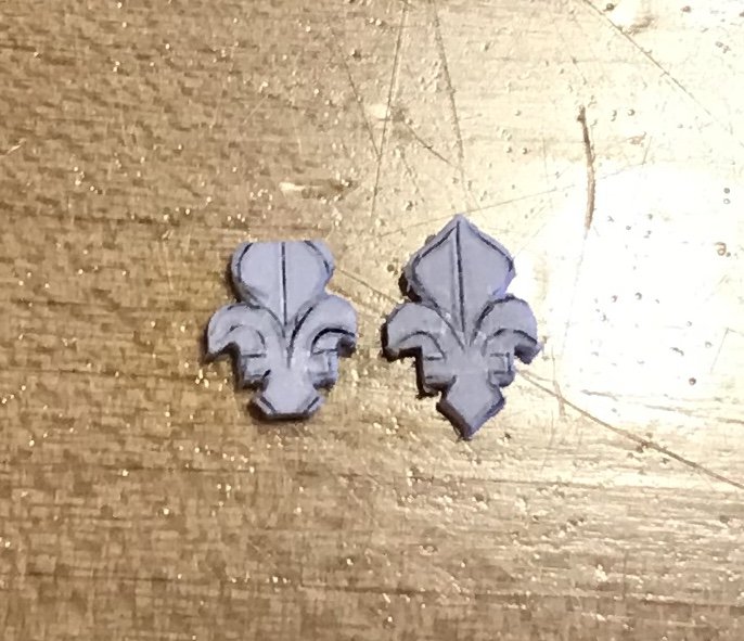
Above is a good comparison of the difference in proportion, from where I started to where I need to be. They should, in fact, be even a little smaller! But, here are two revised flowers, side by side:

My experience, thus far with this casting process, is that I inevitably end up with ornaments that are larger or smaller, depending upon a number of variables related to the process of removing the ground and defining the perimeter. There will be plenty of extras to choose from, that will fill these more narrow spaces without seeming too large, relative to the frieze lattice. Whatever other differences, in size throughout the frieze, should contribute (hopefully, in a good way) to the handmade quality of the model.
I can’t wait for vacation!! 🌞🌊🏊🏻♂️⚓️
- BLACK VIKING, yancovitch, Baker and 7 others
-
10
-
-
Hey EJ - great work on your figure of the “Americas”!
Looking as closely as I can at Berain’s drawing of the stern, it appears that this figure, on the port side, is not holding anything. Her left hand is perched, at her side, upon the arched pass-through that she sits upon. Her right arm is raised, crossing her body with the hand resting on the quarter piece that supports the side lantern.
It is the figure of “Europe,” astride her horse (perched upon the left side of the taffrail) that appears to be holding a pointed spear, or scepter. This would make sense, thematically, as Europe was the dominant continental power, with “Asia” (on the right side of the taffrail, astride her camel), the next leading world power. The neo-classical robes of Europe and Asia are emblematic of their self-conception as developed cultures, while the Americas and Africa are mostly bare-skinned and wearing only primitive vestments.
- Elijah, jay, Old Collingwood and 3 others
-
6
-
-
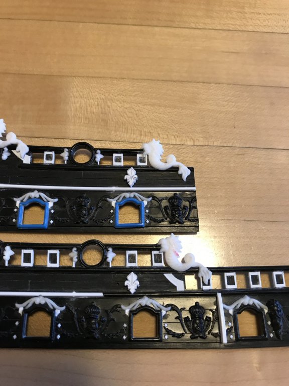
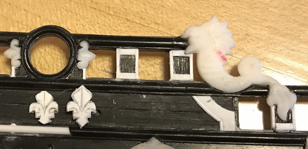
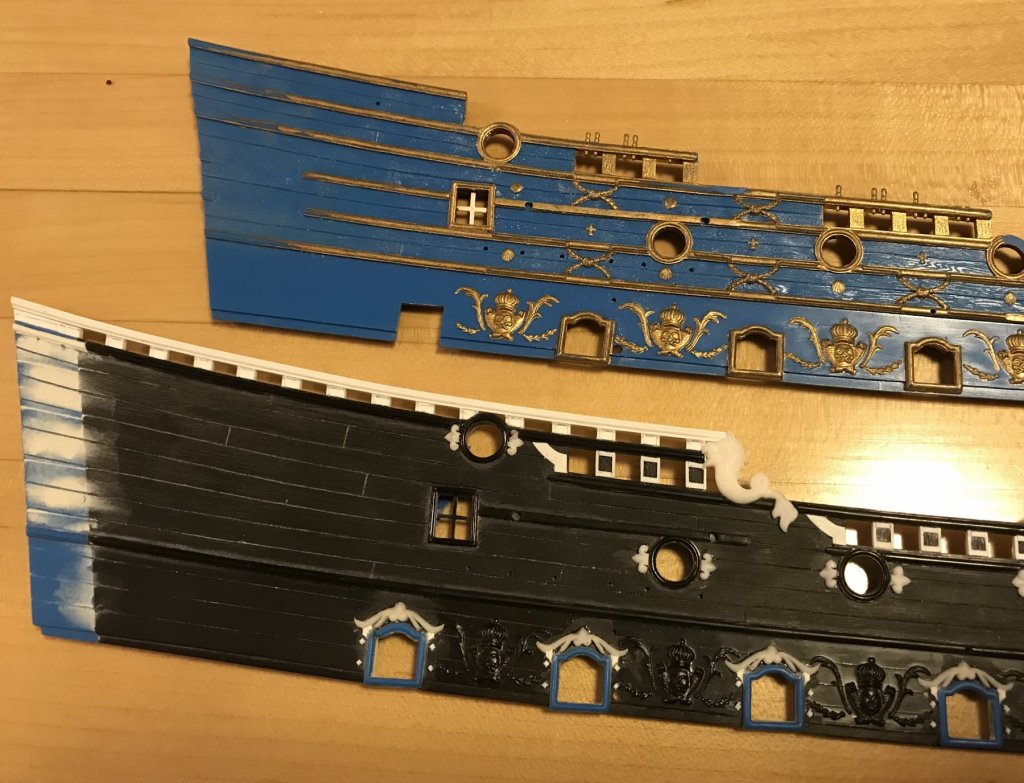
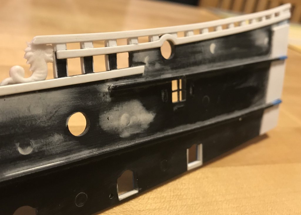
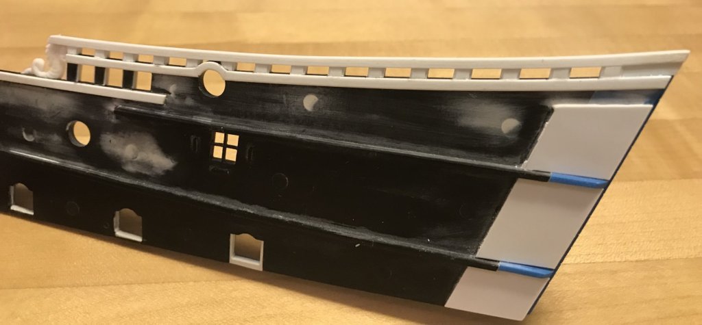
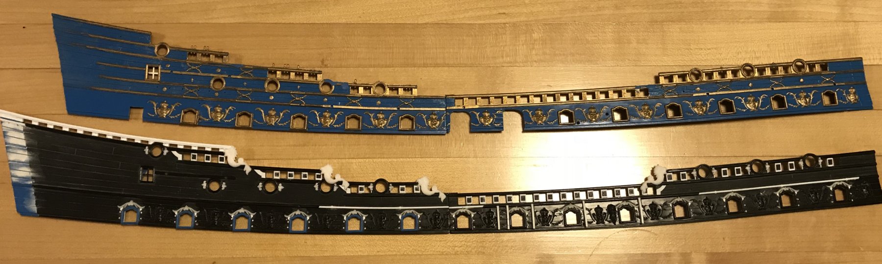
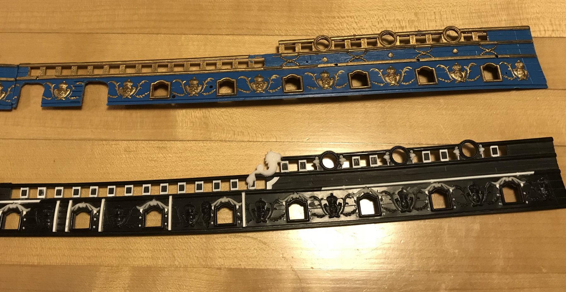
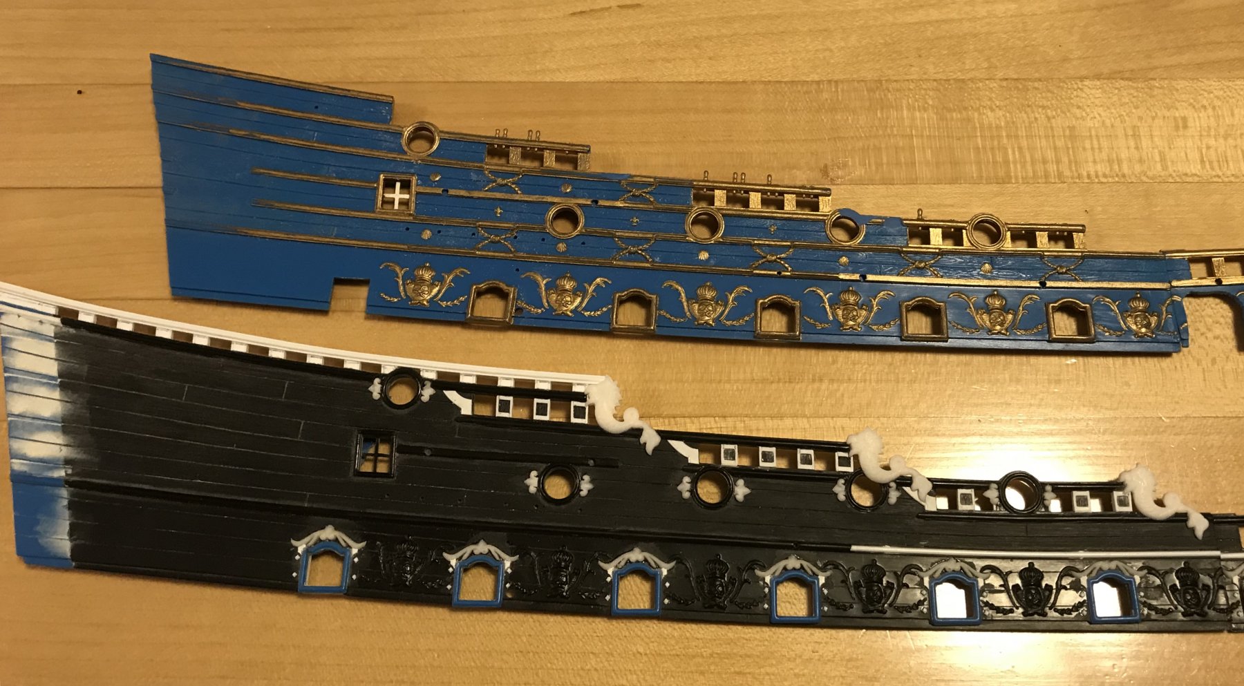
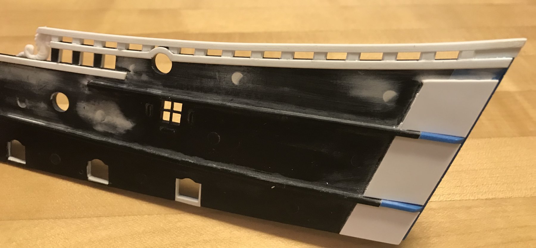
Now that all of the sheer-rail detailing is done, and dolphins installed, and all of the round port enhancements are let in place - here is a bit of a before and after comparison with the original kit parts:


I’d like to note that, only here at the transition from waist rail to the f’ocsle rail, does the dolphin nearly align with the scalloped hancing detail, below it, as drawn by Berain. For the stern upper bulwark pieces, I felt that at least having the dolphins and hancing steps present was enough, without going the extra mileage to extend the piercing of the timberheads, so that the hancing pieces all lined up under the dolphins. In at least one instance on the quarter deck, the presence of a round gun port prevented that alignment, anyway. By not doing so, I afforded myself more room for a more complete layout of the lattice frieze, which I felt was a more important detail.

Now, I will begin making all of the fleur-de-lis, shells, scrolls and folliate diamonds that ornament the new lattice frieze, which will fill all of this newly cleared space on the upper bulwarks.
At some point soon, I will need to figure out where I went wrong in my GIMP drawing process, so that I can print what I have for the lattice frieze and the amortisement of the quarter gallery, to scale. Presently, the entire drawing is crammed into something like 1/300 - 1/350 scale. I made some error in importing the scans of my hand drawing into a workspace that was unnecessarily too large. To work on the drawing, I really have to zoom in. All of this, in some way or how must be why working on the drawing slowed to a near standstill because I had many thousands of data points crammed into too small a space.
Anyway, Much as I would like to, I don’t need to finish the drawing in order to complete the model. It would just be really helpfull to extract that frieze layout because it should be a perfect match for the upper bulwark pieces. I’m also hoping to salvage my bow angel and the trailboard frieze for between the knees of the head.
- yancovitch, Baker, druxey and 6 others
-
9
-
-
-
SPEC-TAC-U-LAR
After shaping the tafferal and compartmentalizing for the zodiac symbols, all of your hard work is rounding into form.
Excellent work on the quarter pieces that support the side lanterns!
I’m excited to see what you do with The figures of Europe and Asia, whom recline upon the taffrail.
-
Hello Doris,
Your figurehead is amazing! There is little I can add to the compliments you have already received, and which are richly deserved.
What I would like to say is how much I like the focused, and incremental progression of your work, as it is reflected in this build log. We are on a journey with you, and your candor with your methods and reasoning, combined with your research are really eye-opening. You have captured the imagination of us all, and that us what I have always thought this hobby was about, in the first place.
KUDOS to you, my friend!
- mtaylor, popeye the sailor, Piet and 5 others
-
8
-
Hello Dziadek,
I meant no dis-respect, and I can understand your faithfully following through with what you have commited to.
Thank you for that link to the Modelbeau website, Jasseji. I was unable to open the instruction guide on my phone because I’m in an area with poor reception. Nevertheless, I believe what you are both saying about the kit instructions is true. It is just puzzling as to why, considering the lengths D’Agostini went to to produce an, otherwise, authentic model.
The only possibility I can think of that makes any kind of sense to me is that, after planking over the stem, one could then veneer over that with an assembly of stem timbers, so that the hull planking appears to neatly tuck into the stem rabbet. This possibility, however, would not provide a similarly neat resolution of where the hull planking meets the stern post; the veneered-over stern post would step down to the planking in this area. Anyway, it is a strange feature of the kit.
I was able to watch the videos, though, and I am impressed by the amount of internal structure that they designed into the model. The laser-cut parts appear to tuck neatly into place without a lot of fiddling - so long as you have squared your construction, along the way.
-
-
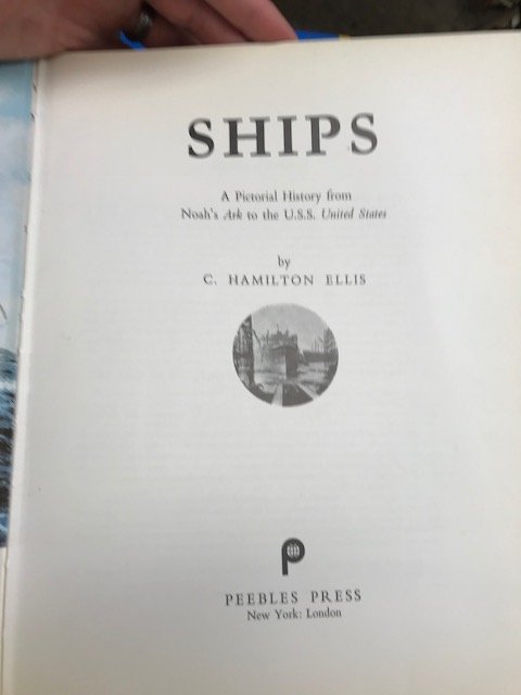
Today, I visited the Strand bookstore, just south of Union Square. I like to go there, when I'm in the area, because they have a decent maritime/nautical history section, and I sometimes find some gems for my collection.
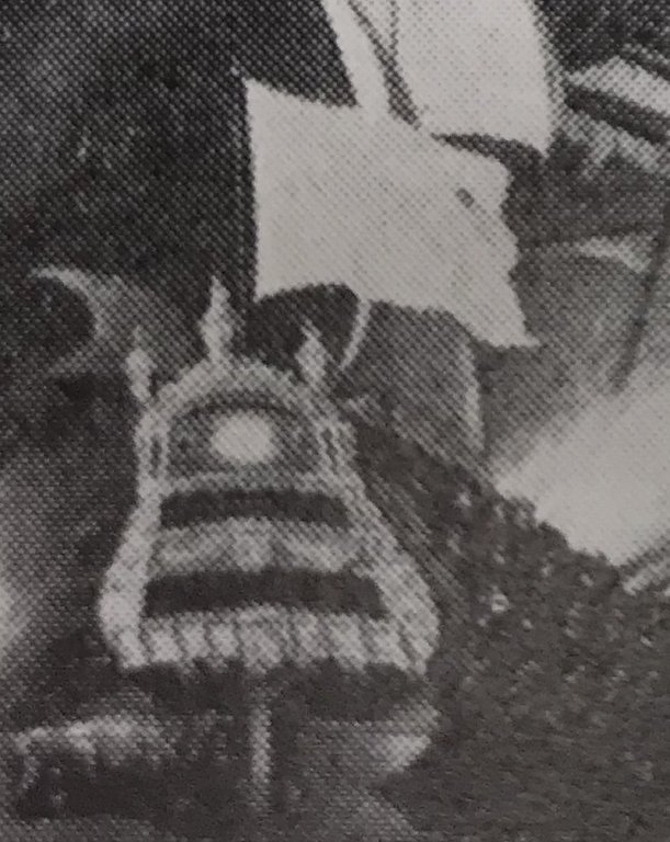
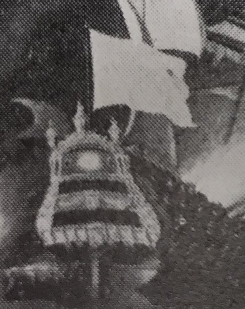
Well, today, I found a different depiction of the burning of Soleil Royal at La Hogue, that I have never seen before. Below is the title page of the book, a picture of the composition as a whole and a close-up of SR:
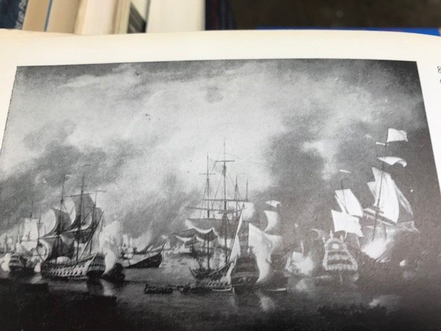
There was no artist attribution in the caption, and I can only guess that the painting was done sometime between 1700 - 1730. I think this may be so because the stern of SR bears little resemblance to Berain's design, and appears to feature set-back, screen bulkheads, where the stern windows are located. To my knowledge, this feature of stern construction did not become commonplace until the first half of the 18th Century, and then, more often on English ships. I'm not positive about that, but I seem to remember that being a point Andrew Peters made in his book, Ship Decoration 1630-1780.
While I don't think there is much that can be taken as literal truth, from this portrait, I like it because it conveys a sense of the drama of the scene and the grandeur of Soleil Royal. Here, Soleil Royal is shown only with two stern balconies, and only two small port windows to either side of the tafferal frieze, on the quarter deck level. Interestingly, the appearance of screen bulkheads and only two stern balconies also appears in the Bakhuizen portrait of Barfleur, where there is at least some vestigial evidence of Berain's design:
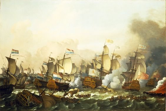
If anyone knows the artist that is attributed to the black and white portrait, above, I would very much like to know who that is.
-
You know, Vic, I think you’re right about this. EJ has imparted so much of himself into his interpretation of the carvings that this model is completely unique. This phase of his build was what I was waiting for most eagerly because EJ seems an ambitious builder, and I wanted to see where he would take it all. Well, he has not disappointed in the least!
- jay, Old Collingwood, Fright and 3 others
-
6
-
I agree with you, EJ, that technology is opening the door for modelers to do previously only dreamed about things. In particular, 3-D printing and 3-D computer modeling are already affordable and accessible options that many on this forum are already using to great effect.
On his excellent scratch-build of the Italian liner, The Michelangelo, Dan Pariser sourced a 3D printing firm to create the complicated, tapering lattice frameworks that surround the ship’s funnels. Could Dan have devised a way to build them, himself? Absolutely. However, sometimes, the computer can do things like this in a fraction of the time and to a standard we can only dream to match. That way, we are free to concentrate our efforts on the other, more rewarding aspects of our build.
-
-


Soleil Royal by Hubac's Historian - Heller - An Extensive Modification and Partial Scratch-Build
in - Kit build logs for subjects built from 1501 - 1750
Posted · Edited by Hubac's Historian
This is mostly a place-keeper post, just to show that something is happening.
I continue to learn interesting (to me, at least) things about the process of making casting masters. On previous ornaments, I was perplexed as to why - when the ground was sanded/cut away - the ornament seemed larger, all around, than the masters.
Well, I finally realized that the thin-set cyano I am using to mount the masters to their stamp blocks, leaves a corona of squeeze-out around the perimeter of the master, which is not really visible to the naked eye, yet it leaves an impression in the mould medium. In the end, this results in quite a lot of re-profiling of the cast blanks to bring them back to scale.
Sorry that I do not have any pictures of this phenomenon. Hopefully, I have described it adequately. This time, I was carefull to scrape away the cyano squeeze-out from the master block and the resulting moulds were much cleaner.
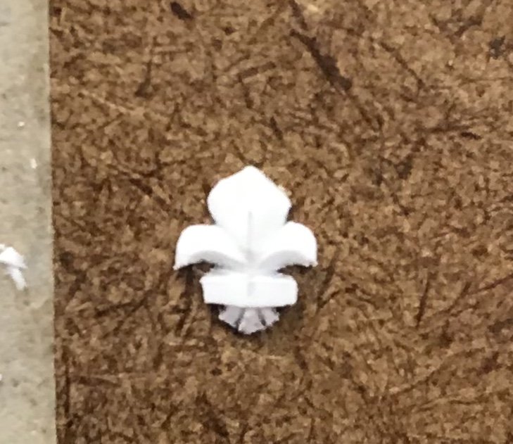
That being said there was still quite a lot of cleanup and re-shaping involved, after cutting away the ground. Here’s a rough blank with the ground removed:
Here’s that same ornament after clean-up and some re-shaping:
Here are fifty ornaments that have gone through that process, and then have been given the once-over, again, in order to maintain a level of consistency among them all:
This is more than enough to select from for the upper bulwark frieze, and I’ll have a good number left over for the port lids, although I will still need to cast more when I get to that stage of the build.
What is not evident in the above pictures is the decision I made to change the profile of the side fronds of the fleurs from my original intent in the mould masters.
Ultimately, with my mind set on the fact that the frieze will be dense with ornament - I decided to soften the frond points and cut the fronds a little closer to the ornament centerline. We’re talking slivers of an inch, here, but repeated many times, over an area, this should help balance the visual weight of the ornaments, relative to each other.
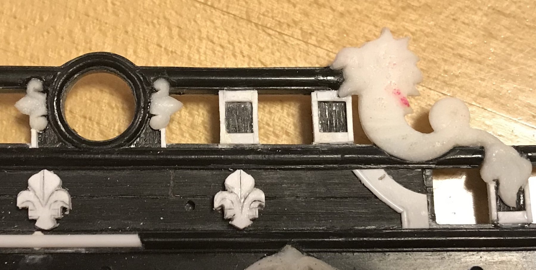
Hair-splitting, yes, but worth the extra effort, IMO. Next up, I will make the many small frieze scroll ornaments I need:
These little things (on every pointy end of the frieze lattice) are really tiny. I’m not sure this casting process is the best method, as they are roughly 1/8” wide by 1/16” high and I need A LOT of ‘em! I haven’t gotten around to taking an actual measurement yet, but they are tiny enough that it is hard to imagine going through any advanced effort at sculpting, over and over again.
I wonder about making a punch that I could use to stamp these things out easily and quickly from 1/32” styrene sheet. I could then use the same technique I used for the wale through-bolting, to create tiny domed accents for the scroll heads, that I would apply to the scroll with a dot of glue.
This would give the scrolls just a bit of shape and dimension, as opposed to being a completely flat stamping.
Does anyone out there have any relatively easy advice on making such a small punch, or any ideas on an alternative approach to this particular ornament? Is this, perhaps, an ideal application for 3-D printing?