Hubac's Historian
-
Posts
3,315 -
Joined
-
Last visited
Content Type
Profiles
Forums
Gallery
Events
Everything posted by Hubac's Historian
-
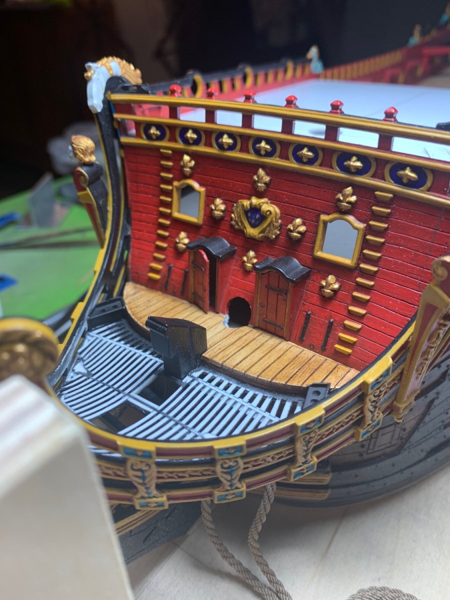
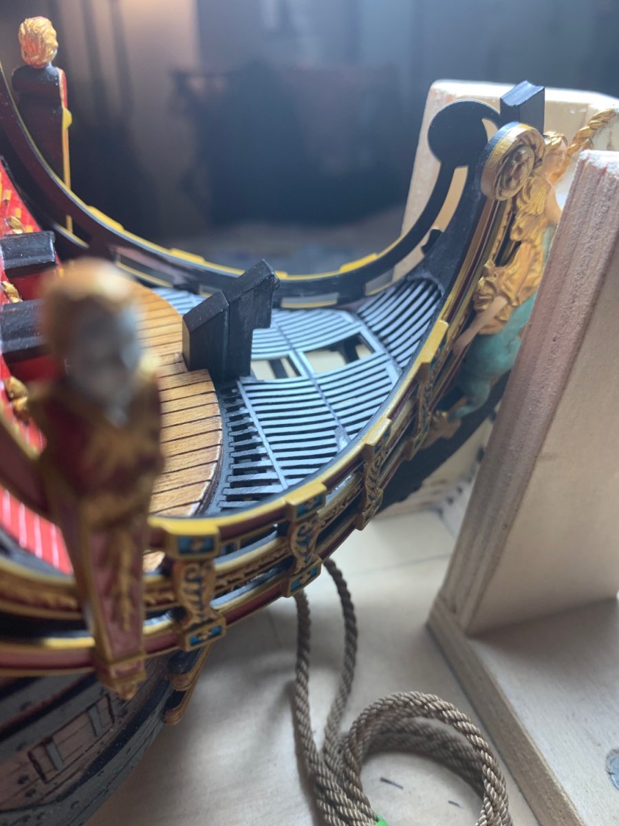
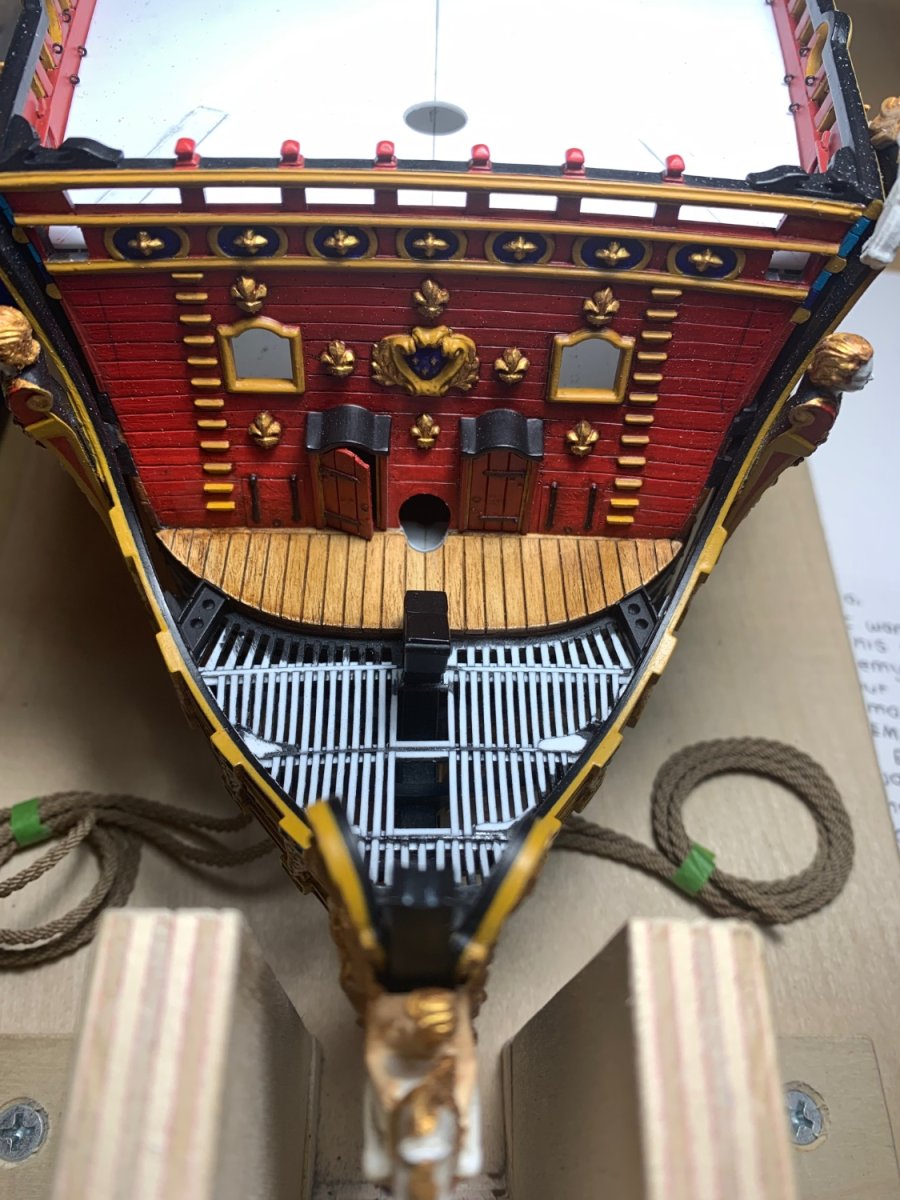
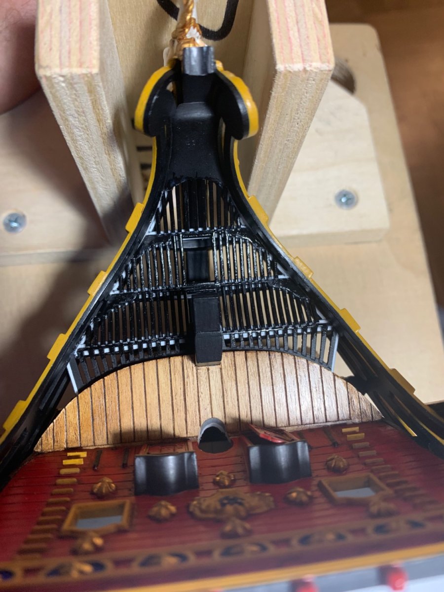
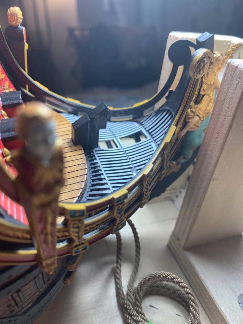
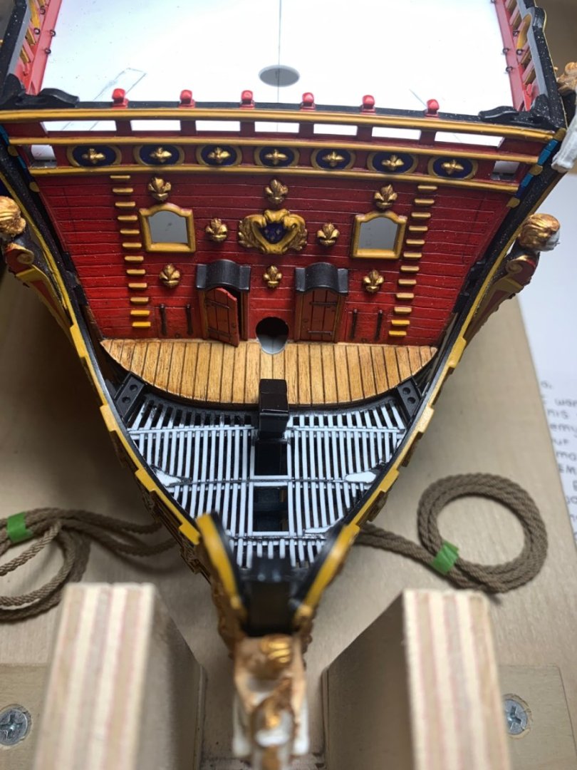
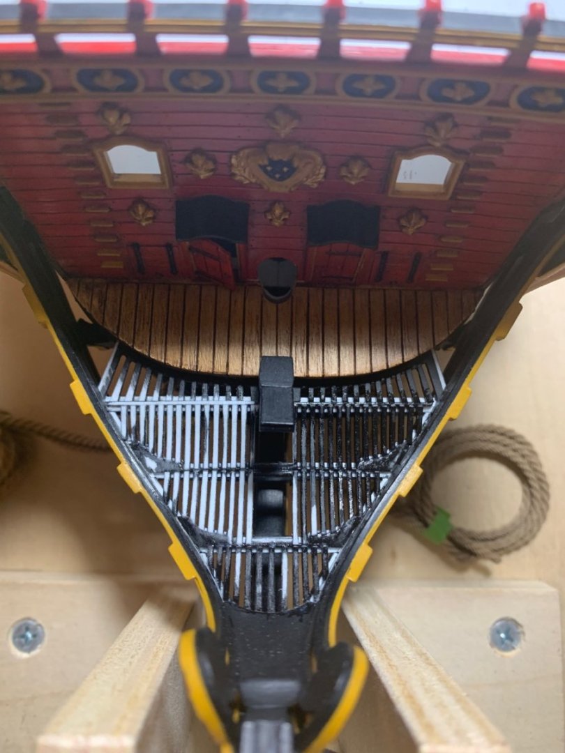
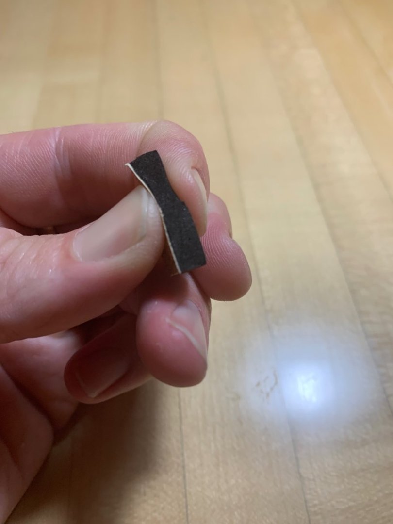
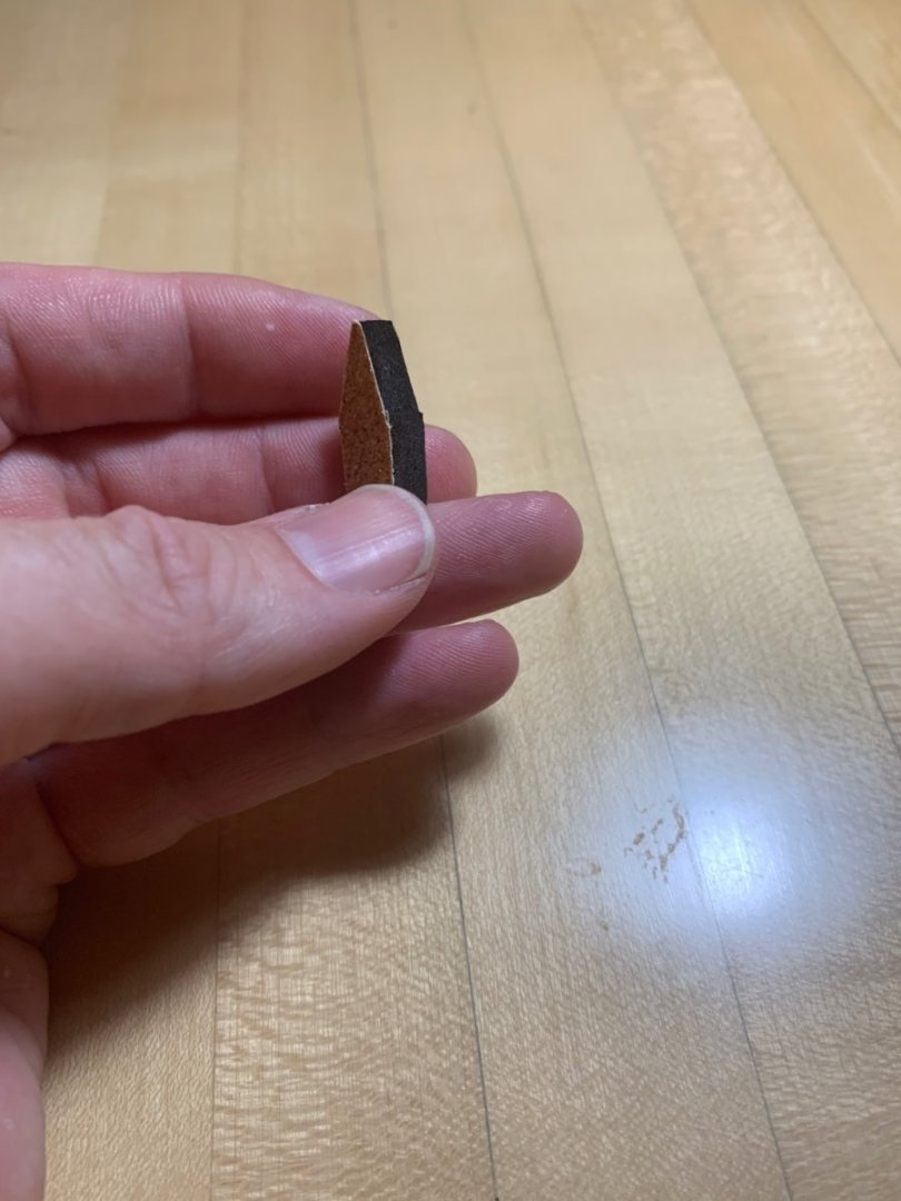
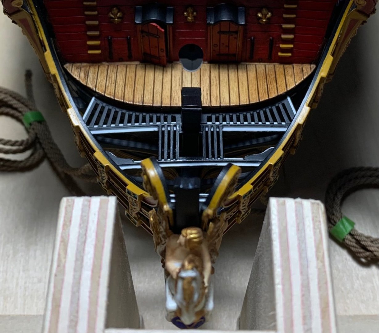
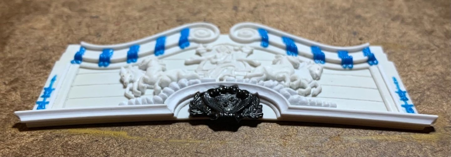
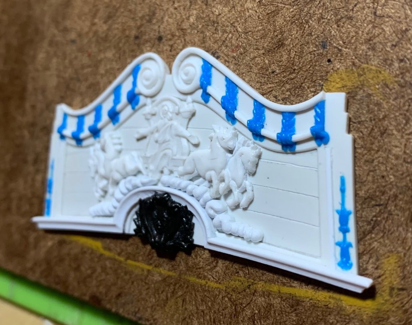
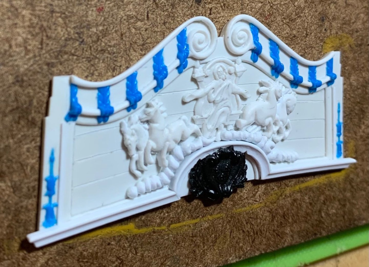
 The head grating was remarkably tedious to make, and I can honestly say that I did not enjoy any aspect of this process. I began by making a series of styrene strips for the slat stock that followed the curvature of the headrails. Each segment had to be cut to fit and placed by hand: I used a drafting compass to get approximate measurements at each location, and then it was a lot of filing and test-fitting until each slat bridged the span perfectly. After all slats were initially cemented with styrene glue, I brushed the whole assembly with thin CA - the Crazy Glue variety. I like this stuff for certain applications. It dries with some body to it, so it is good for something like this where it “keys” into the spaces between slats, and locks them firmly in-place. This is important for the sanding/leveling process. I made a semi-soft sanding block from sanding foam, and double-stuck a piece of 100 grit paper to its face: Then I’d manipulate this sanding block with a pair of tweezers and a finger from my off-hand. It took a bit of effort, but I faired out the surface without dislodging any slats: In the white, the following angles show the ‘thwartship camber of the grating pretty well: Finally, I could fix the new seats of ease in-place: In an episode of “you couldn’t do it again if you tried,” I impaled my left hand with a pair of pointy tweezers that I dropped and tried to catch, as I was attempting to place these seats. One tine went pretty deep! Fortunately, my tetanus booster is up to date. Now all I have to do is prime and re-paint. Thank you all for stopping by! More to follow..
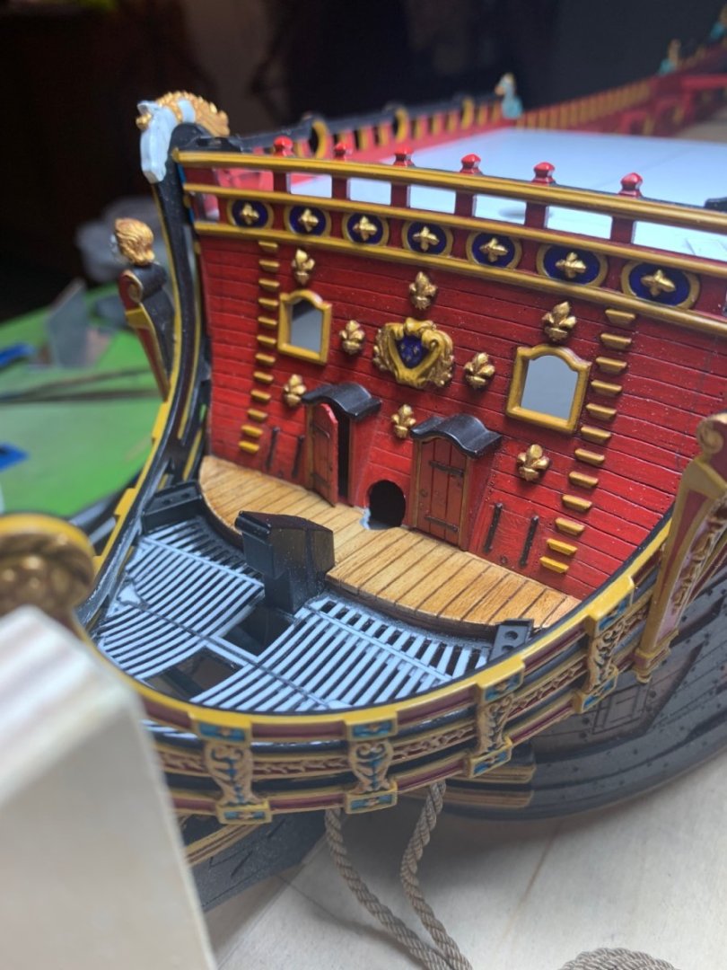

- 2,699 replies
-
- 20
-

-

-

-
- heller
- soleil royal
- (and 9 more)
-
That lower hull looks incredible!
-
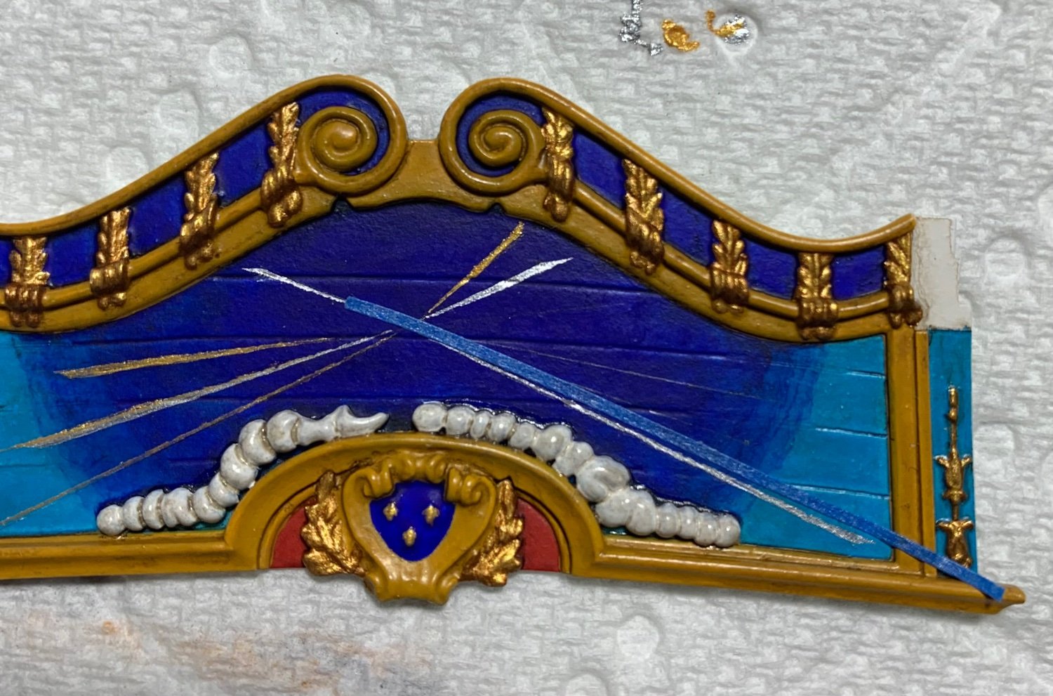
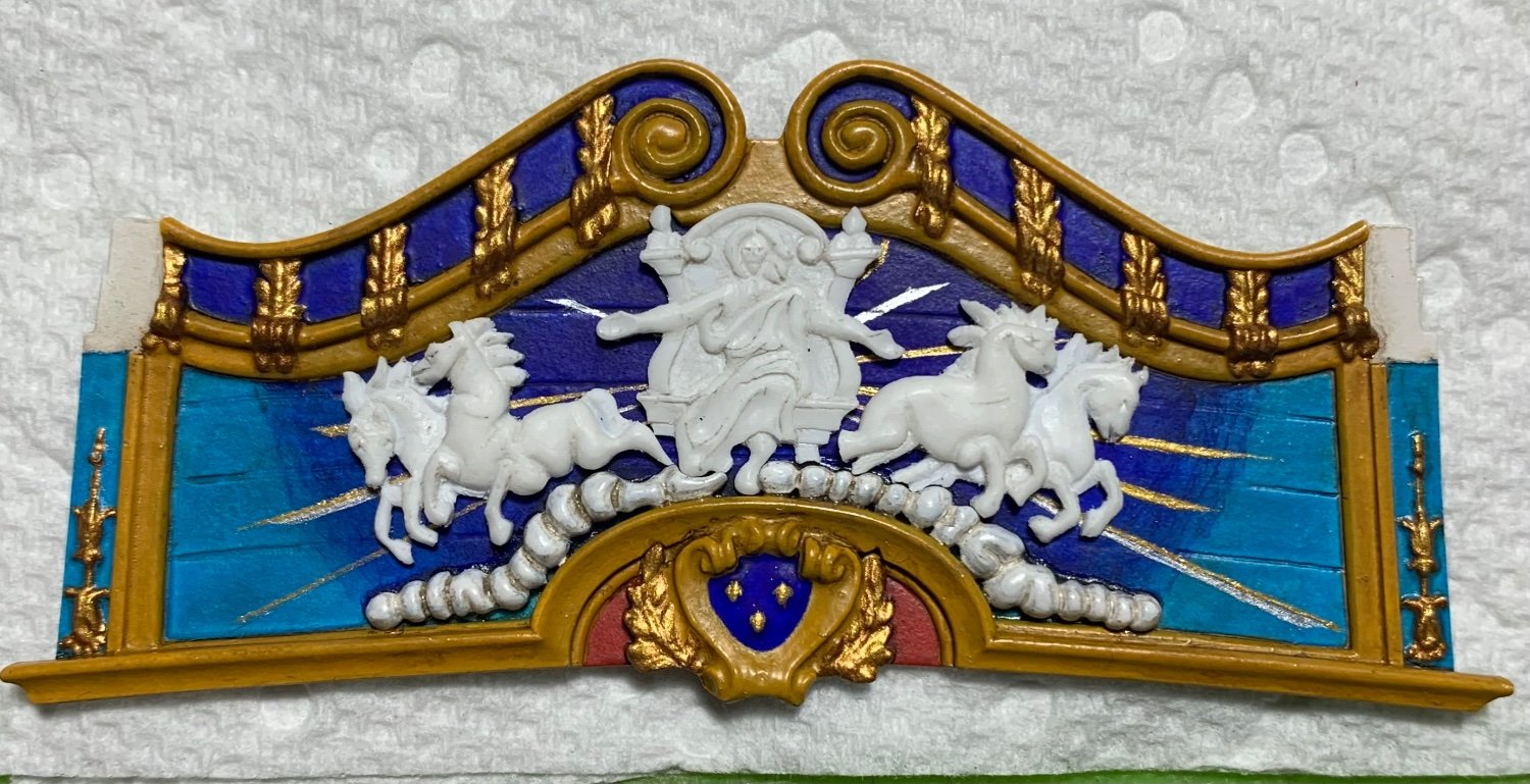
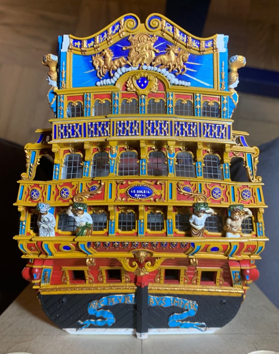
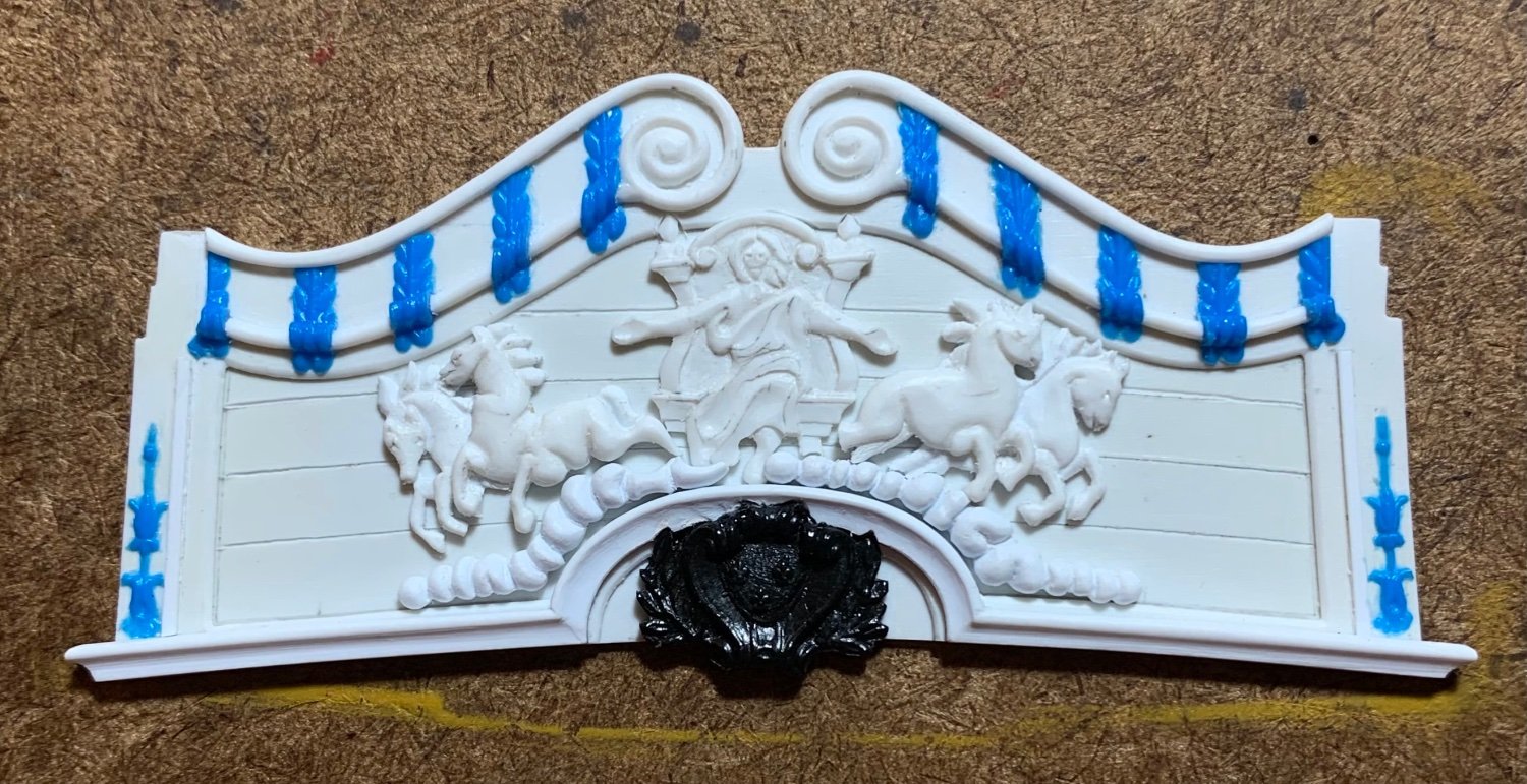
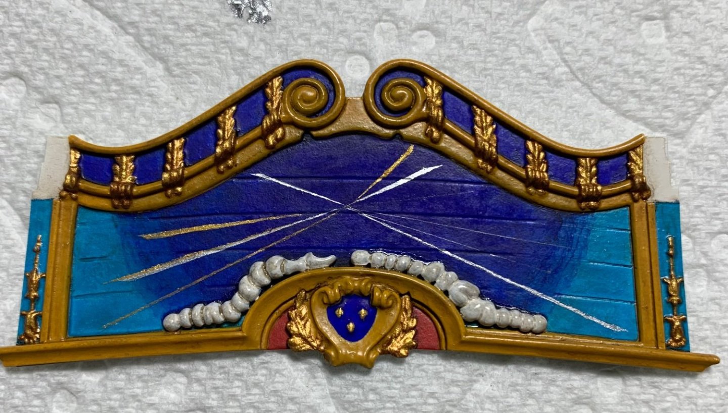
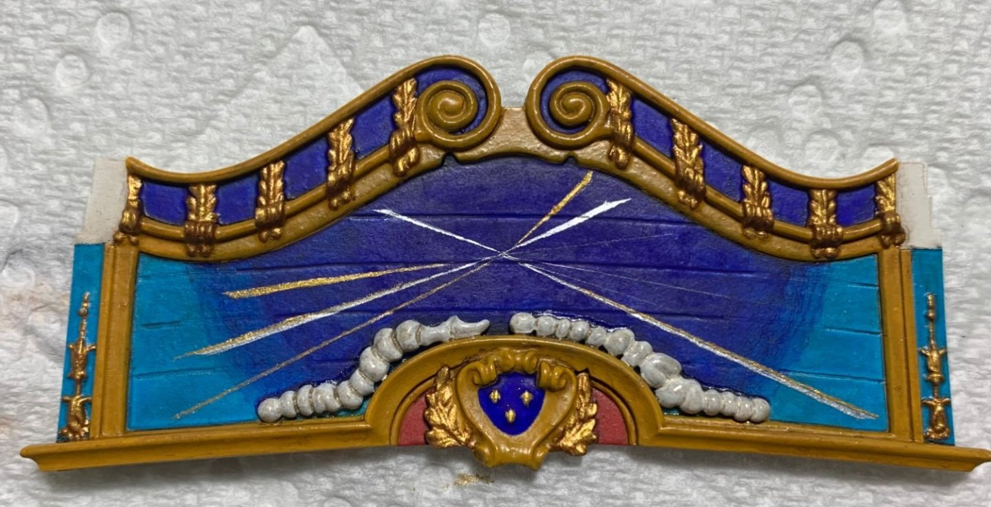
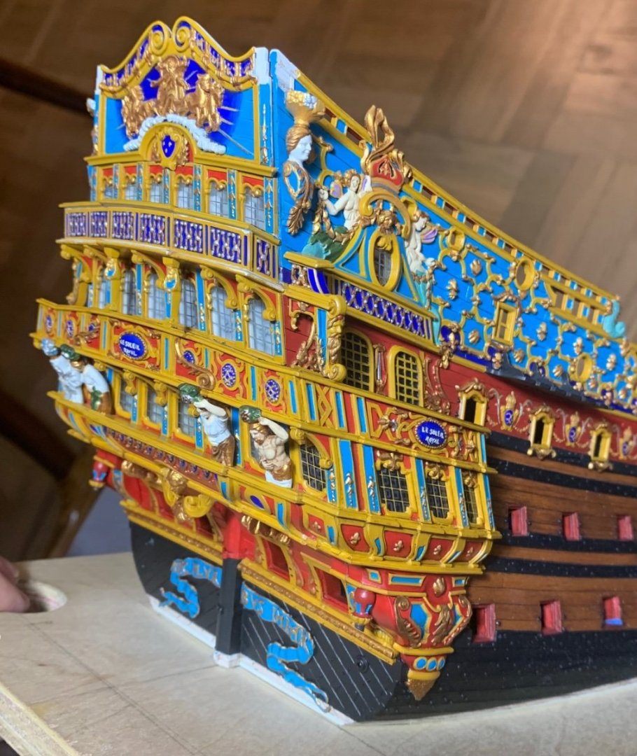
Painting the shards of sunlight, emanating from behind the Apollo carving, is tricky because the field is so small; the available space doesn’t really allow for masking both sides of the line. My solution was to first draw pencil guidelines for each sun ray. Port to starboard symmetry should be avoided for a detail like this. I wanted lines of varying length and tapering thickness to extend beyond the horse and chariot carvings, from a variety of angles. The idea was to lay a strip of tape as an additional guide to the pencil line; this way, I could run my brush over the tape side of the sun ray and nudge the wet edge carefully to the pencil side of the ray. It was important to remove the tape while the paint was still soft, otherwise the tape would likely lift the finer sections of the painted ray. As I have throughout the ship, I wanted to incorporate silver gilt with the gold. As Eberhardt (if I remember correctly) once pointed out, this would have been unlikely on the real ship, but as an artistic choice it adds to the visual impact of the thing. In the photo sequence below, I am adding a thin gold line to the previously painted silver line of a single ray: On the starboard side, you can still see my faint pencil (6H) layout for the remaining rays to be painted. It was occasionally necessary to go over sections of these ray lines with a wet brush, when the tape did lift small flakes of paint. As fine as these lines are, these repairs are manageable over short sections because most of the line remains as a visual guide. After painting the clouds and applying a grey wash, I placed the carvings to get a sense for the whole composition: In my estimation, this is just enough radiant sun to convey the idea. After gilding the carvings off the model, and carefully scraping paint away to fix them in-place, here is a preliminary view of what the backboard looks like on the model (not glued yet): There are still a few mouldings to be fixed in-place, and I have not yet painted the side lantern brackets. From the side view, this impression of depth is what I was hoping for: You can see the tiny Zodiac symbols that I painted into the cornice top. The acrylic paint pen wasn’t quite fine enough to do this, practically, so I simply sketched a basic approximation of each symbol in its opening with a hard pencil. I then carefully painted over the pencil lines with my finest sable brush. Considering the scale, they are little changed from the moulded versions on the stock stern plate. At the present moment, I am considering how I will paint the two Continental figures of Europe and Asia that sit atop the cornice. Their clothing will definitely be painted in a more naturalistic fashion, like the Four Seasons figures. I think I have the colors figured out. Gold will be used sparingly. The main thing is that their faces and any other exposed skin will be painted grey-washed white. I’ve done this for the quarter pieces, the cathead supports and most notably the figurehead; there is something about this approach that is reminiscent of classical statuary, which were the original inspiration for these carved works in the first place. In any case, this approach avoids the thorny issue of representing different regions of the world in different skin tones. More to follow - thanks for stopping by!


- 2,699 replies
-
- 16
-
-
-
- heller
- soleil royal
- (and 9 more)
-
Just spectacular.
-
HMS SUSSEX 1693 by 8sillones
Hubac's Historian replied to 8sillones's topic in - Build logs for subjects built 1501 - 1750
This would be a tremendous resource and I hope that you will do so. Perhaps it isn't necessary to open a new topic, but just to continue following the final shots of the finished model? Whatever you choose to do, you will have an attentive audience. This is just awesome work! -
I do. In fact, you have persuaded me to do the same on mine.
- 1,508 replies
-
- 2
-
-
- Le Soleil Royal
- Heller
- (and 1 more)
-
I think this came out great Bill! The CA should be more than adequate to close those links. My solution to this problem was to make my channels so that the deadeye strop slots are open. I’ll make the chain assemblies in their entirety, tack them onto the model with CA and small pins, as you have done, and then I’ll glue a small cover strip over the deadeye slots.
-
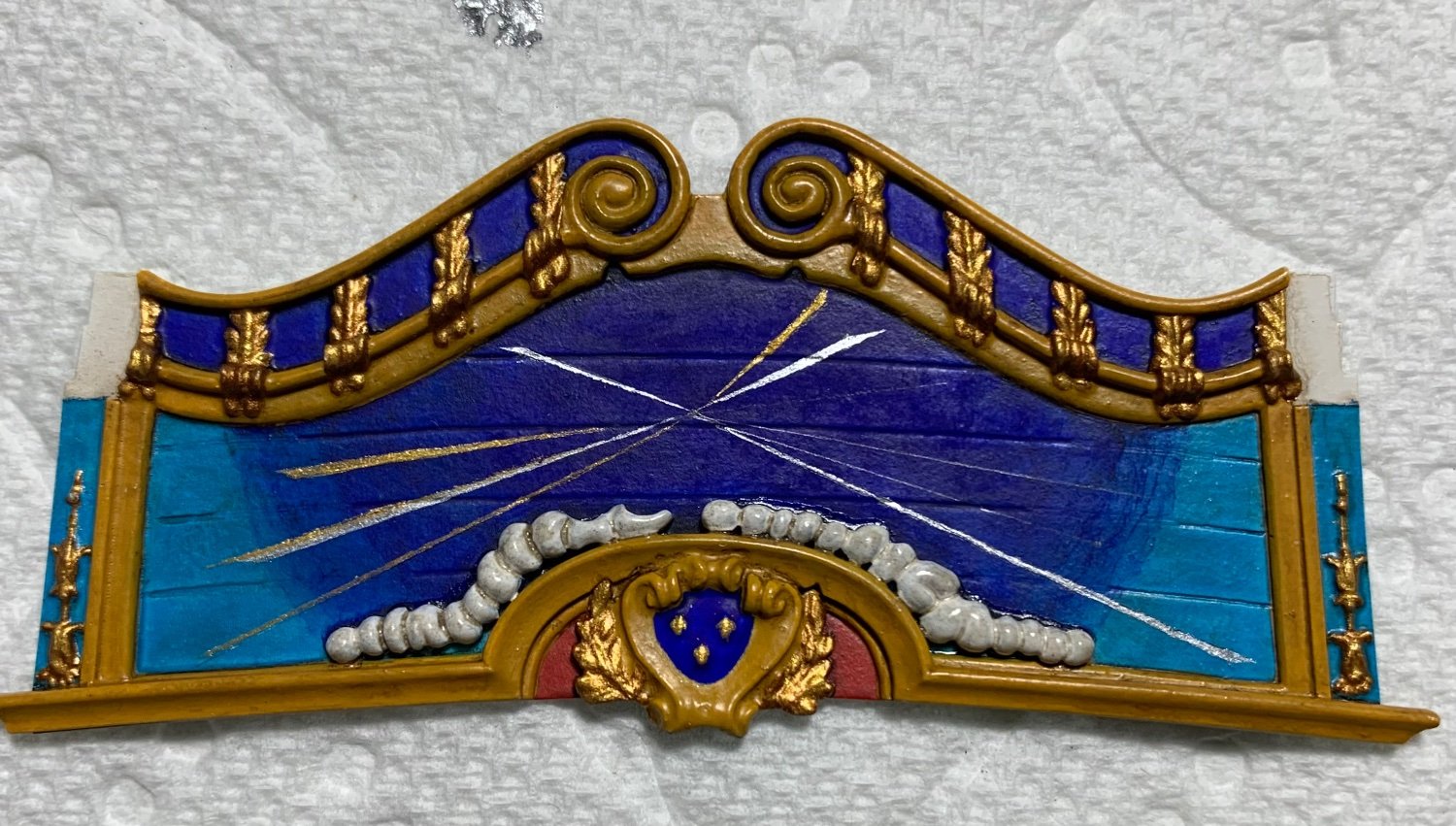
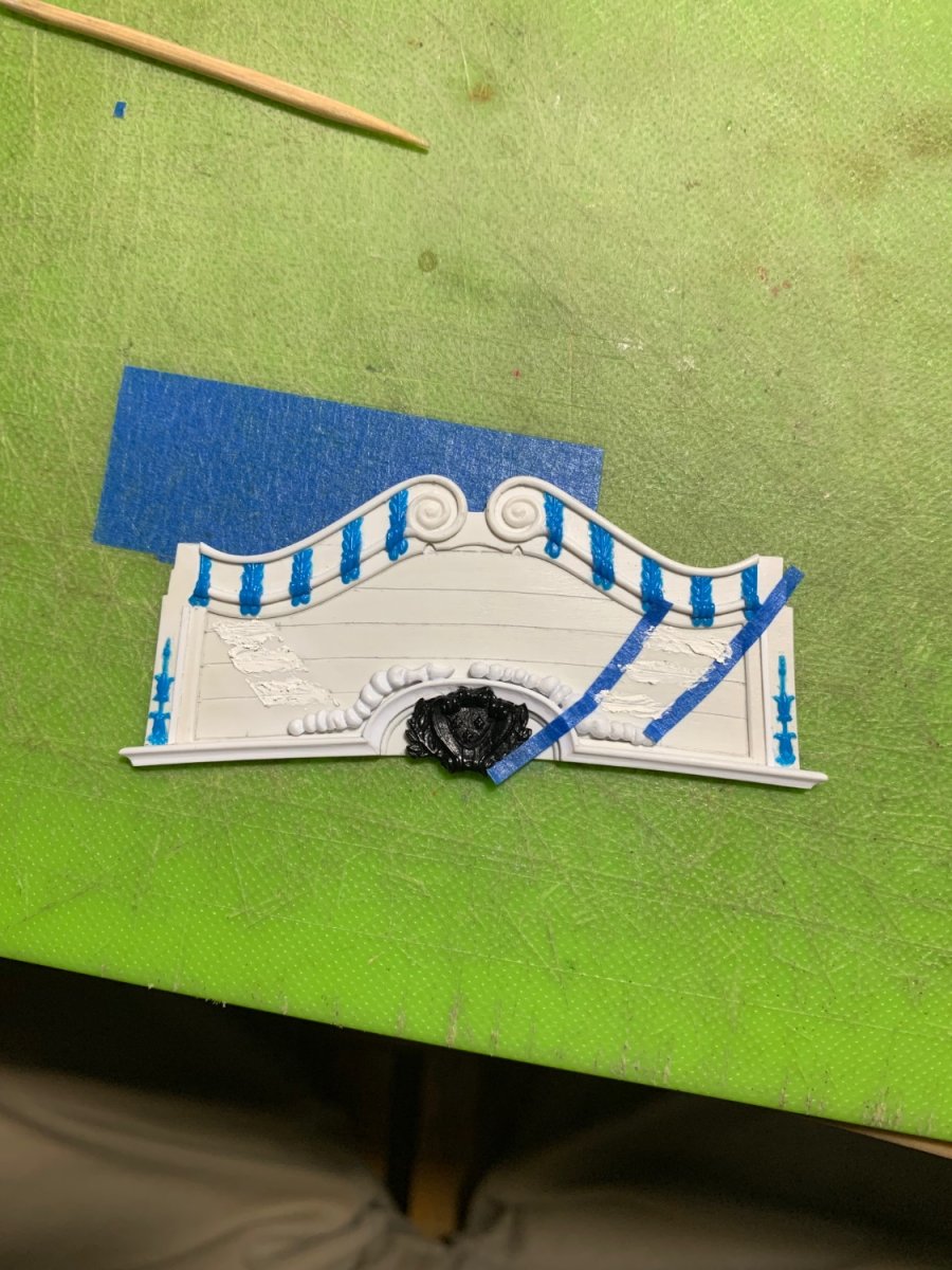
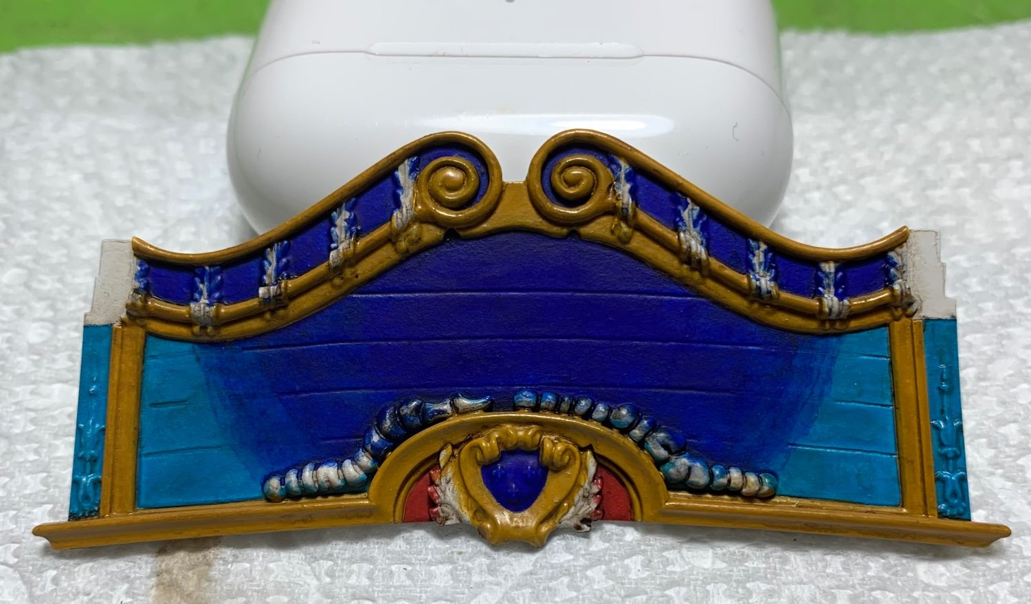
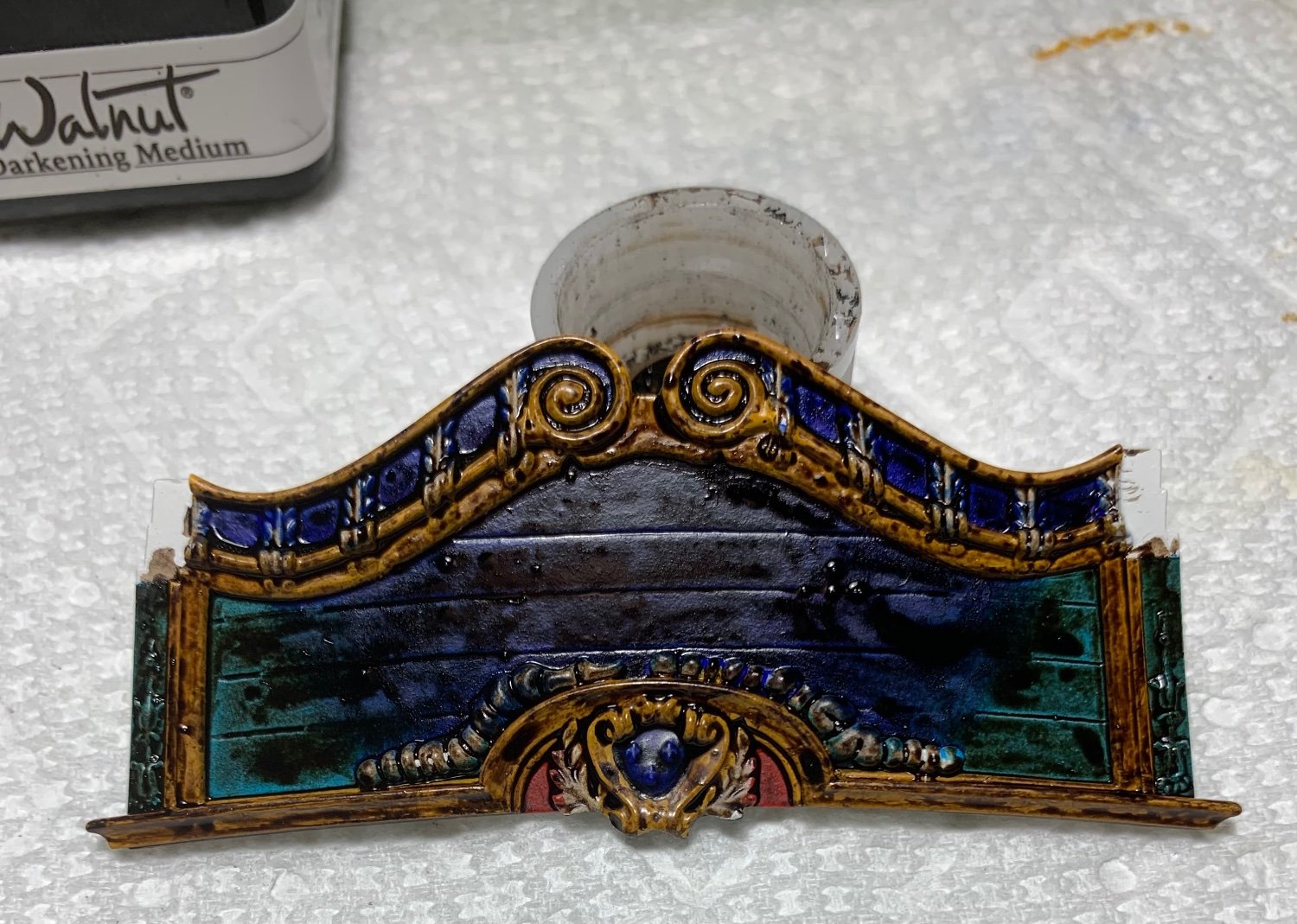
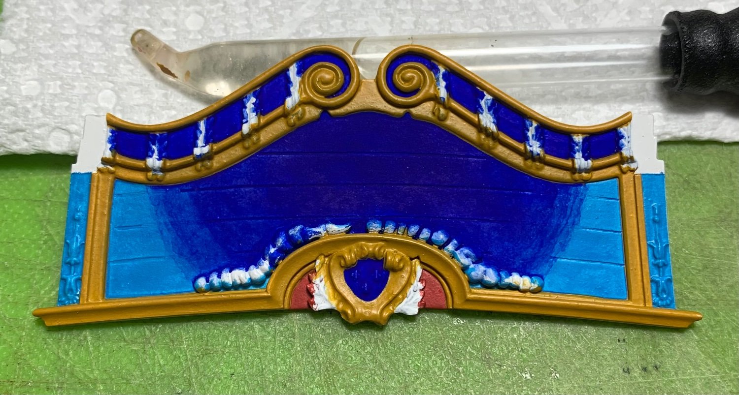
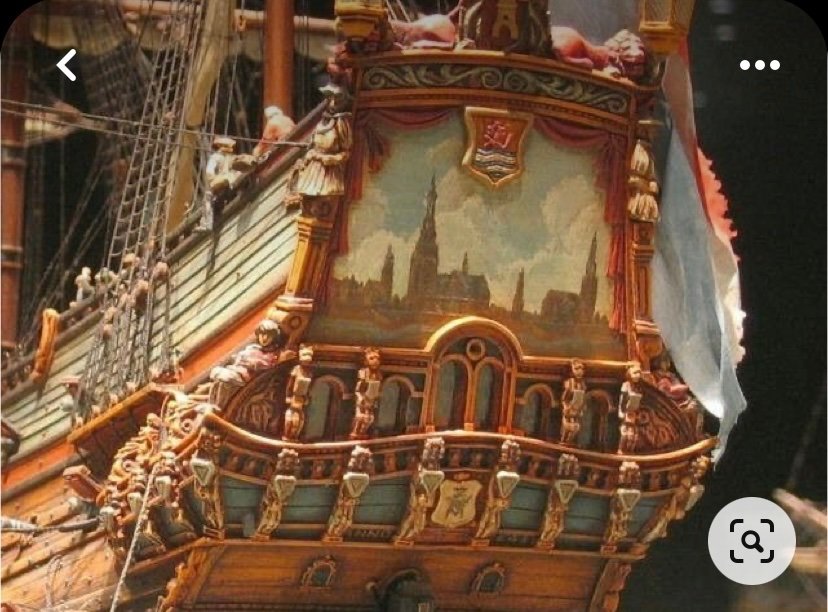
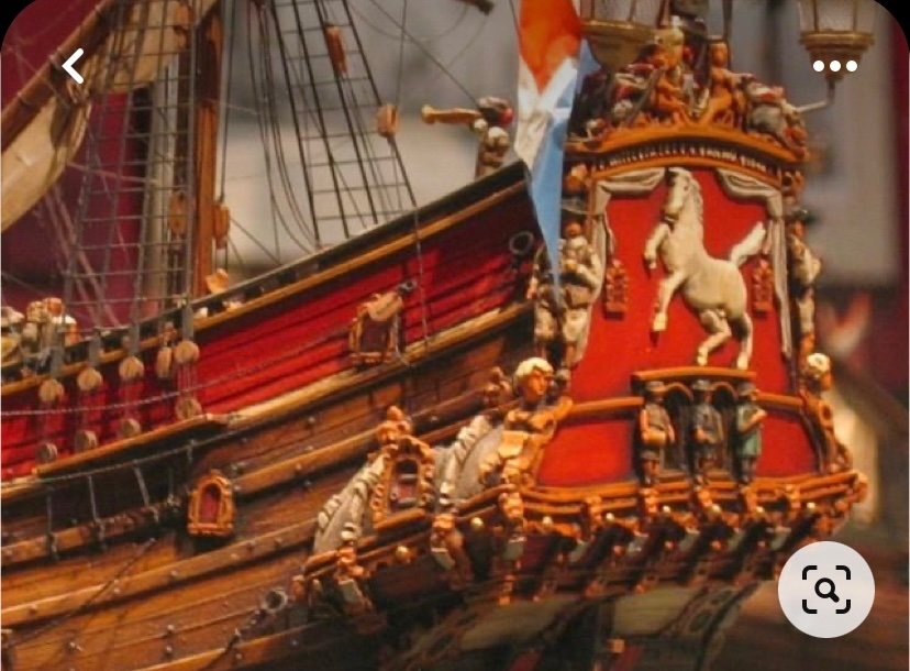
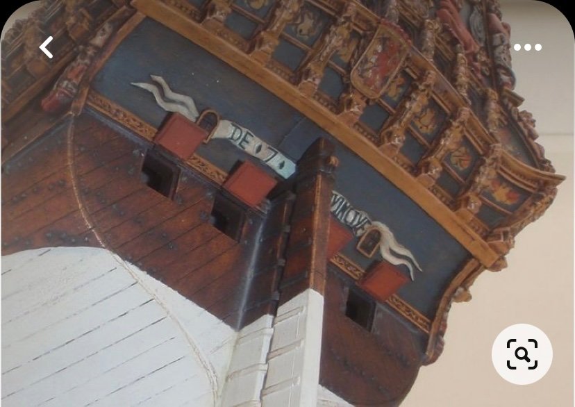
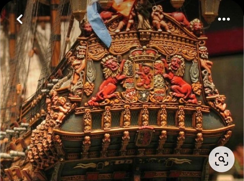
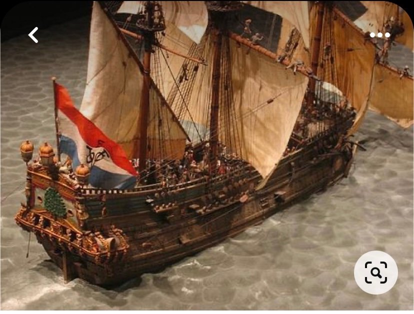
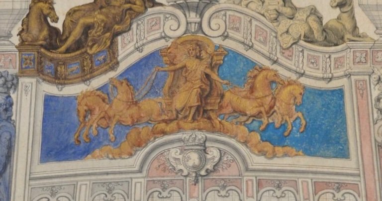
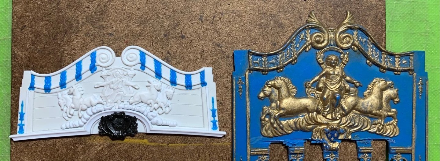
Thank you, Gentlemen, for the kind words and the likes. I hope I will not alienate too many of you with my next foray into the unconventional. I have always liked the painting of the backboards on the Dutch ships. A few stellar examples of Herbert Thomesan’s work: I pulled these images from my Pinterest board Navies of Other Euro Nations. Herbert is a master of color, texture and shade. I take much inspiration from his use of vivid, complementary colors, and naturalistic painting of ornaments and the backboard paintings that illuminate the ship’s namesake. I have started painting my backboard. I want Apollo and his four horses to appear as though they are coasting just on the periphery of our atmospheric realm. Key to this effect is a softly diffuse transition from our earthly cerulean sky to the deep blue of the cosmos. It occurred to me, though, that the plank seams that I scribed into the backboard would make this effect near-impossible to achieve because the successively thin layers of ultra-marine would want to bleed along the seams. My solution was to putty-in transitional arcs to both sides: The horse carvings will distract the eye from these small areas where it is visible that the plank seams disappear. A base coat of cerulean blue went down first, over the entire field. I then applied successively thinner coats of ultra-marine from the top center, feathering out to the sides. This was just a patient process of application (maybe 10-12 thin coats) and adjustment with a wet brush. I got the diffuse effect I was after: Now, to tone-down the brightness - a thorough slathering in walnut ink: Once this dries, I take a wet brush and begin pulling away most of the color until I’m left with just enough patina to make it interesting: There is still adjustment to be made with the weathering, but that will be a blending process after the backboard is attached to the model. Next, I can sketch-in the Zodiac symbols. I bought a fine-line acrylic paint pen to make that easier. The clouds will be painted white and washed with grey. The ornament will get the usual two-tone gold, except for the three fleurs on the coat of arms, which will be bright gold. My plan is to also mask for fine shards of sun light, in gold and silver gilt, to be emanating from behind Apollo and his horses. This will be difficult to achieve without overdoing it, or otherwise ruining the blue backdrop. Thank you for your continued interest. More to follow..


- 2,699 replies
-
- 12
-
-
-
- heller
- soleil royal
- (and 9 more)
-
This is all uniformly excellent. I will follow with great interest!
-
Wow - do you happen to have other detailed close-ups of that Sophia Amalia model, Michael?
-
Beautiful railings, Siggi. You have probably said so, somewhere earlier in the log, but I am wondering whether you plan to do a full masting and rig job.
-
Thank you, David. Yes, I was delighted at the difference - much more than I was hoping for.
- 2,699 replies
-
- 3
-
-
- heller
- soleil royal
- (and 9 more)
-
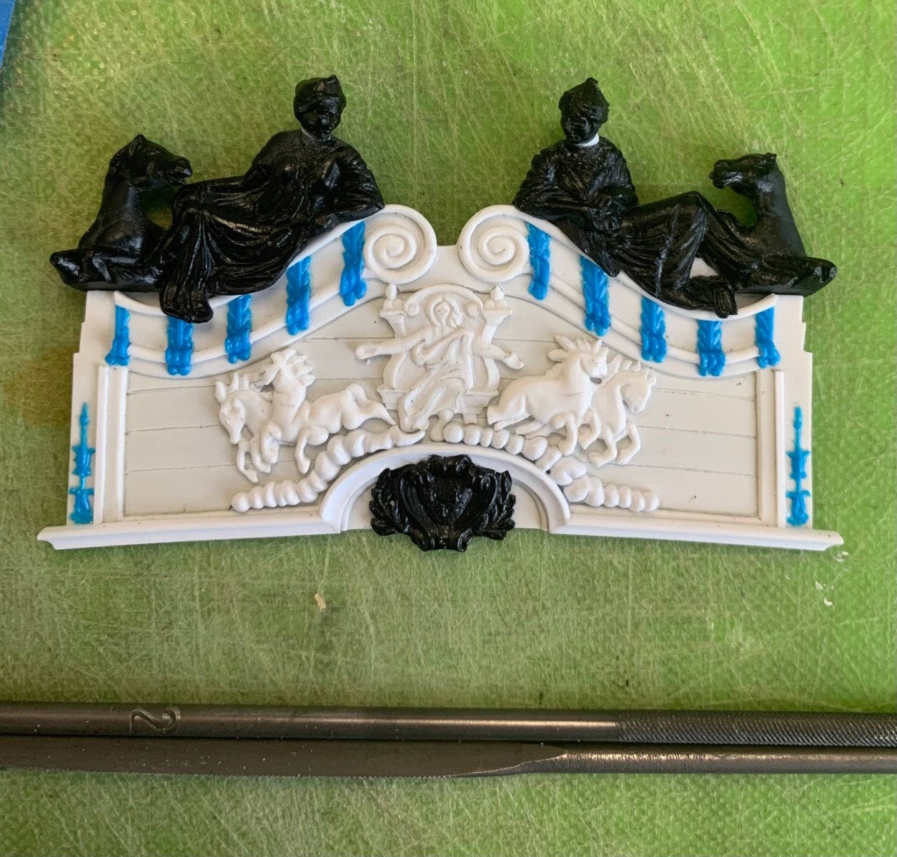
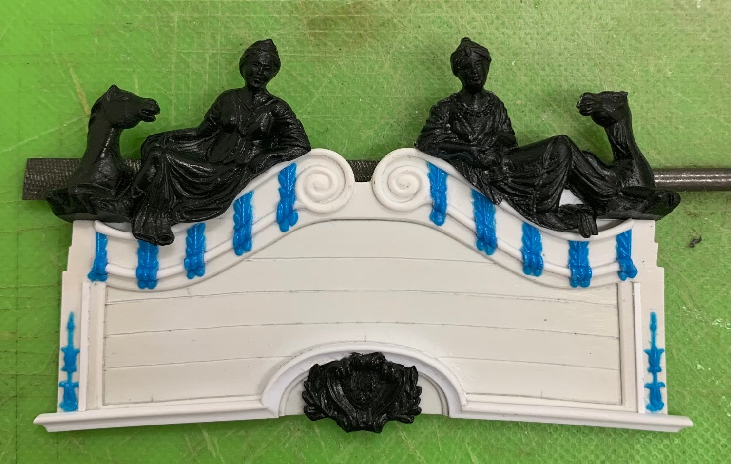
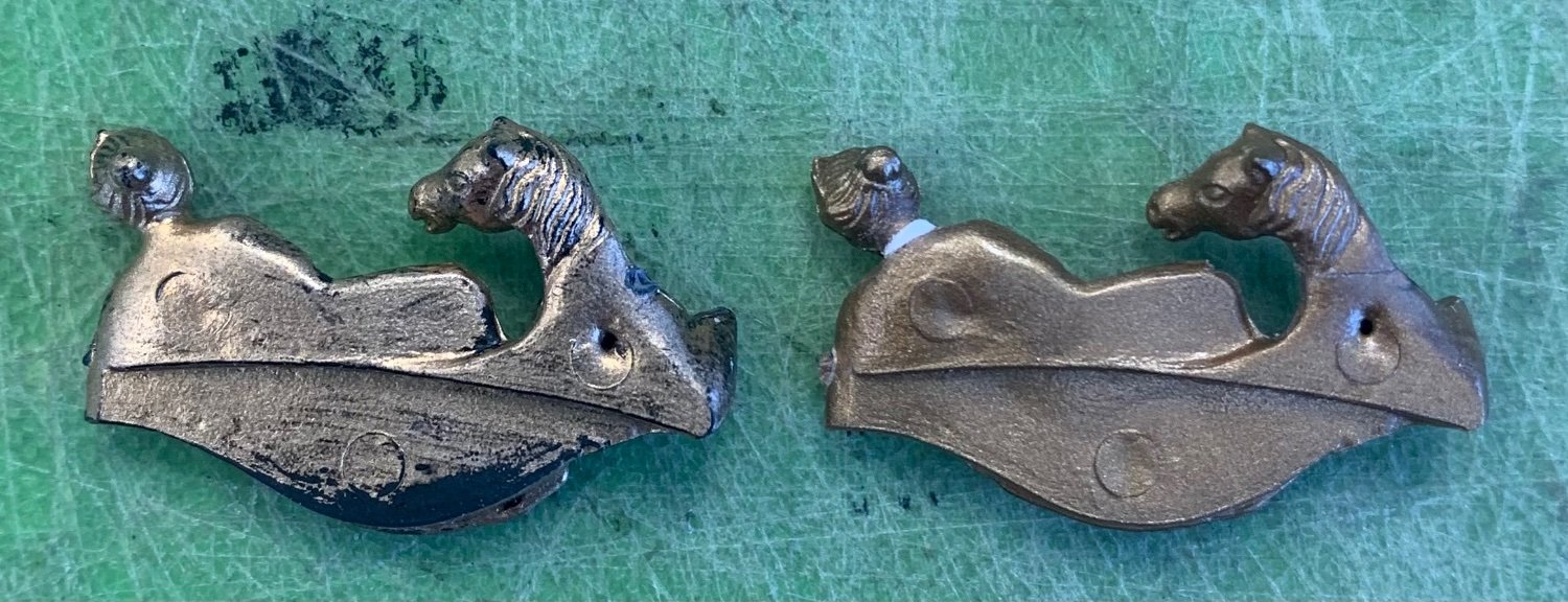
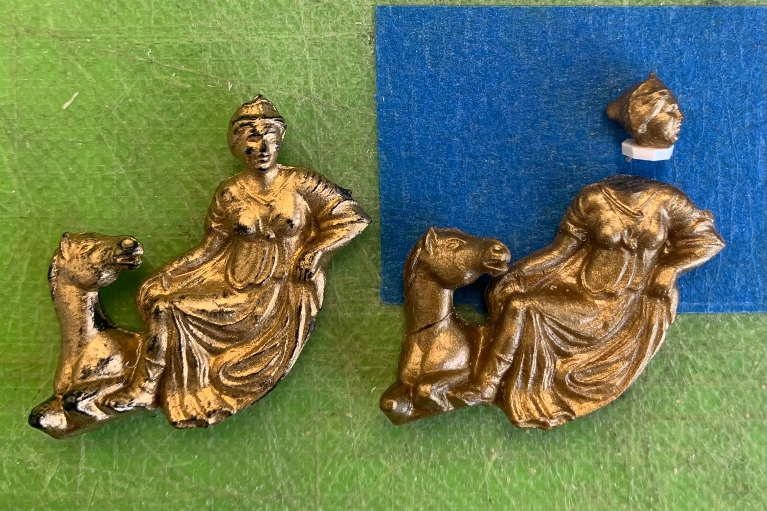
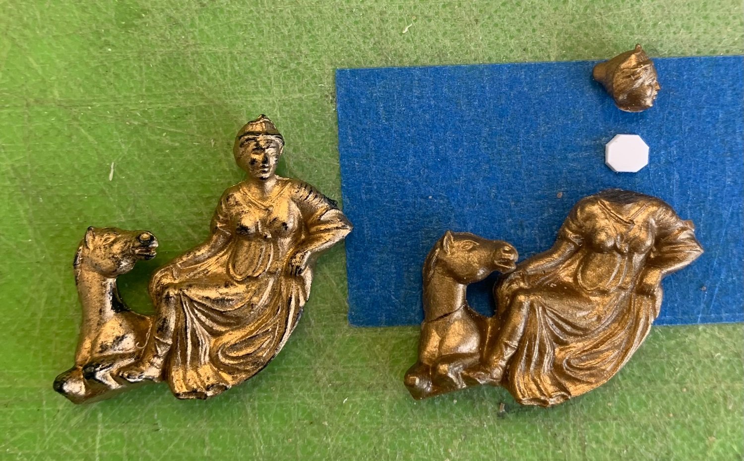
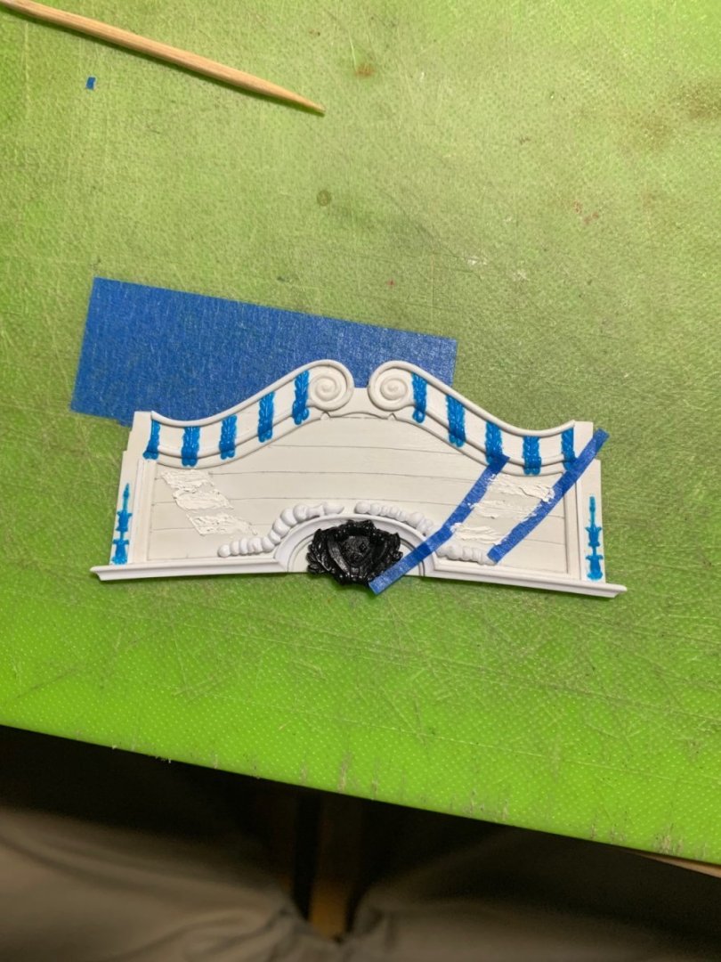
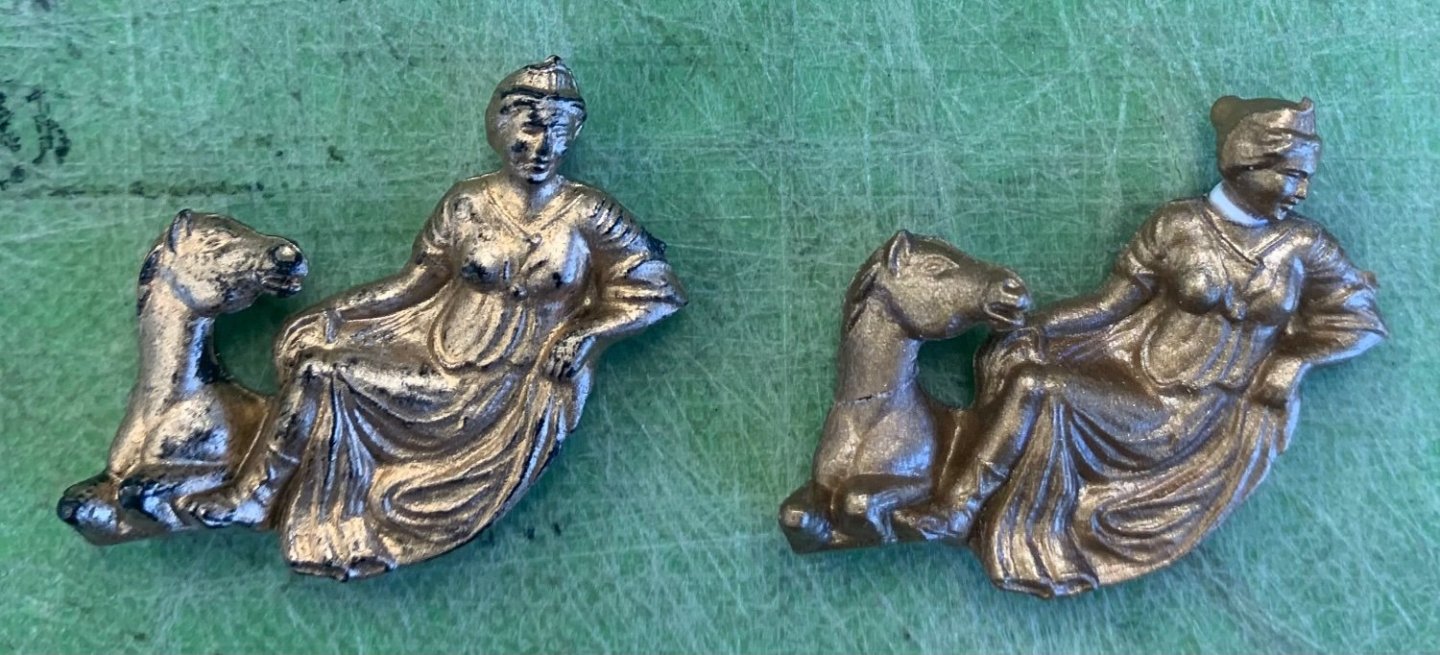
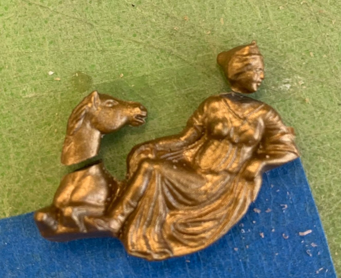
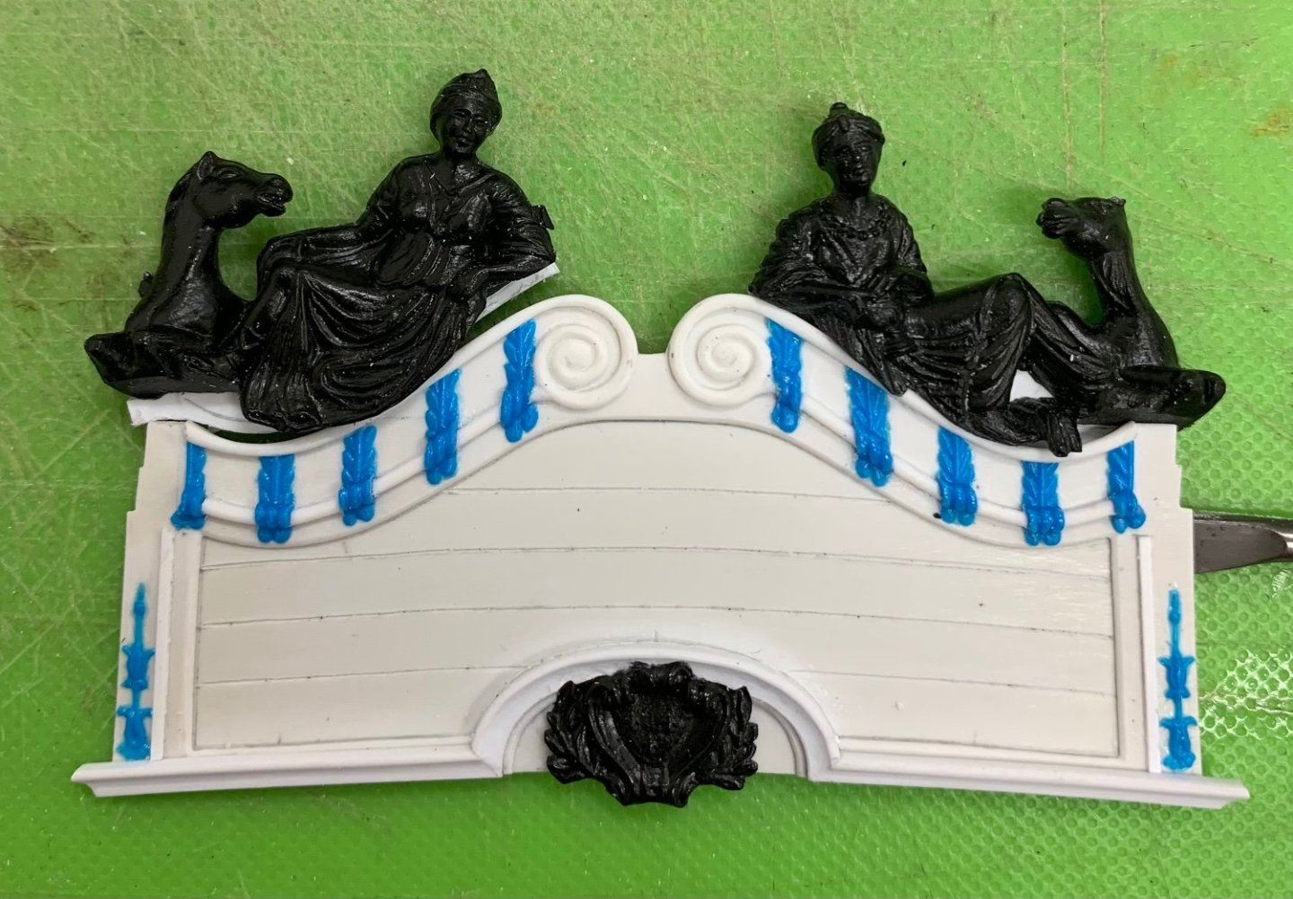
I’ve been debating, for a little while, whether I can improve the scale of the Europe and Asia figures to better complement the shortened height of the stern. After the initial round of fitting and back-fill, the figures look like this: The problem I’m having with this is that these figures were designed to sit atop a taller backboard, and now the horse and camel necks seem a bit too long to me. Fortunately, I have a number of spare parts with which I can experiment. I had an idea that if you cut the animal heads at the right angle, the kerf loss and clean-up would reduce their head height just enough, and the rejoin could be easily faired. I also, while I’m at it, wanted to see whether I could decapitate the continental figures, themselves, in order to correct the angle of their gaze; they should not be staring out blandly at Soleil Royal’s wake, but instead be lovingly focused on the carving of Apollo, below: And, so, I put on my surgical gloves and got to work: The horsehead is rejoined And after filing an angle into her neck insert, so that her chin drops: The differences are subtle, but the modifications are not difficult to make. Now that I’ve seen that it can work, it doesn’t seem so risky to modify the figures that I’ve already invested a ton of work into. I’m still cobbling together the head grating, in the evening. That is all looking very promising.


- 2,699 replies
-
- 14
-
-
-
- heller
- soleil royal
- (and 9 more)
-
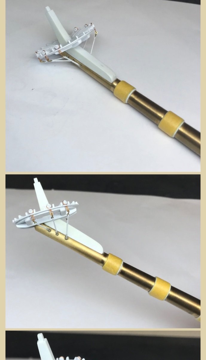
More from Duarte:
-
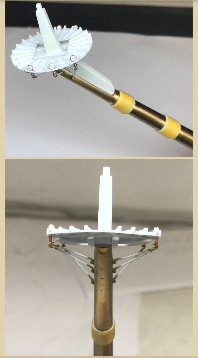
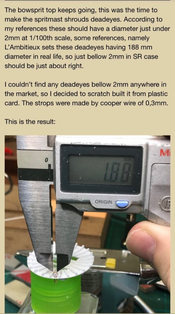
Here is what one friend on another forum is doing with his sprit top. He scrapped all the Heller sprit-mast parts, preferring to make them all from scratch. Here is Duarte’s solution: I will copy this approach, myself.


- 1,508 replies
-
- 1
-
-
- Le Soleil Royal
- Heller
- (and 1 more)
-
That’s a nice detail on the anchor stocks, to make them appear as two halves. I’ll have to remember that when the time comes.
-
Thank you, Michael. If by castings, you are referring to the large continental figures, then those are actually just the stock kit parts that I have modified. All of the blue ornaments were simply extracted from a spare stern plate.
- 2,699 replies
-
- 4
-
-
- heller
- soleil royal
- (and 9 more)
-
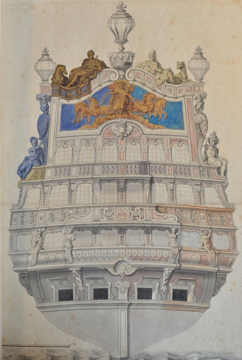
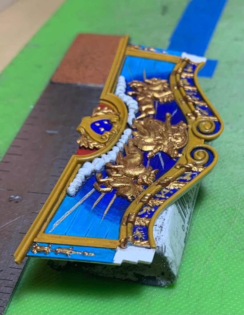
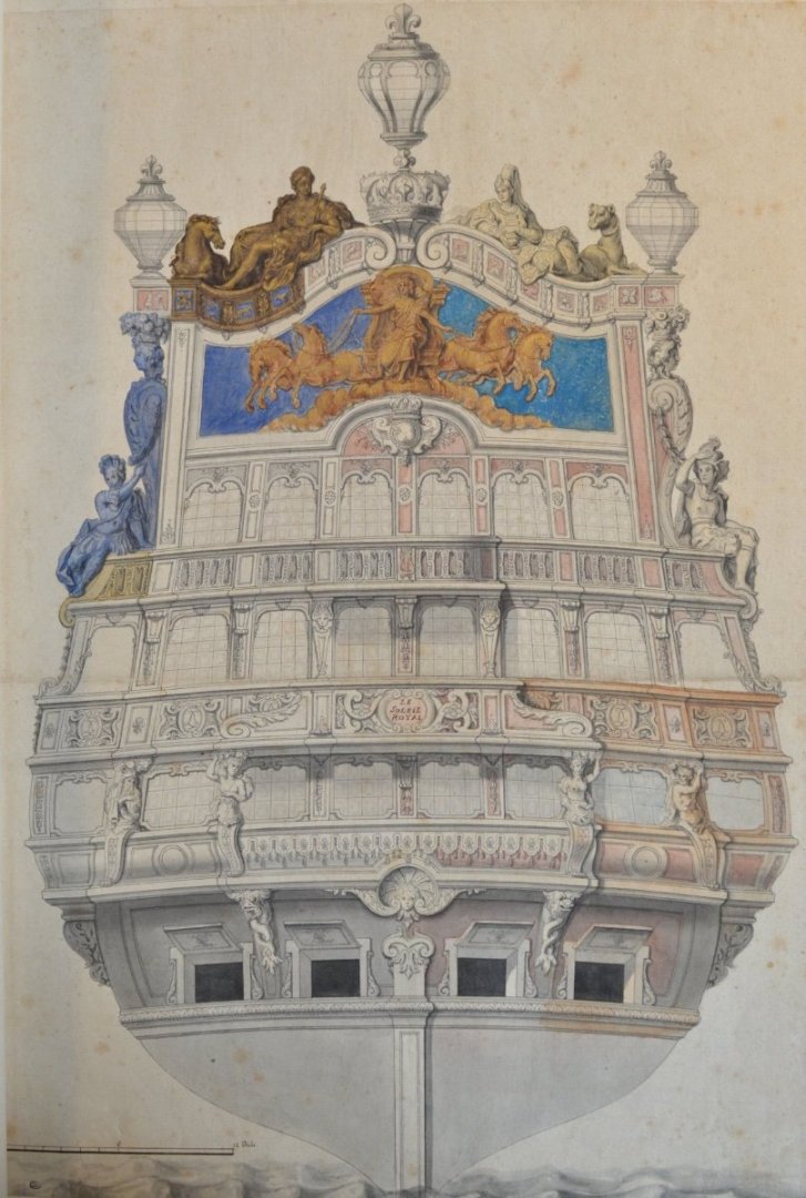
Time well spent: There is some sense of foreground and background. The proportion of the carving, relative to the area of the back board, closely copies the Berain drawing. I am happy. It is fascinating to me how different this is from the stock kit. Thanks for looking-in! More to follow..

- 2,699 replies
-
- 21
-
-
-
- heller
- soleil royal
- (and 9 more)
-
I believe the mizzen mast locates in a square hole on the lowest battery deck. It can only go so far. If the square pin locates properly, you shouldn’t be able to rotate the mast after it is seated. If you didn’t true-up that square locating hole before closing up the deck, that may be a slight problem. Either way, the mast can only go so far.
- 1,508 replies
-
- 1
-
-
- Le Soleil Royal
- Heller
- (and 1 more)