


ahb26
-
Posts
285 -
Joined
-
Last visited
Content Type
Profiles
Forums
Gallery
Events
Posts posted by ahb26
-
-
Some progress to report. I completed the planking on the open side of the boat:
.jpg.a18fe63e16a9d29d34870c1c182096df.jpg)
After sanding both sides with coarse and medium grit paper and doing some filling, I applied clear shellac diluted with denatured alcohol as a sanding sealer, and sanded with 400 grit paper. I also trimmed and sanded the planks overhanging the transom
.jpg.67152570ab2359c7d6c86b5d5d17c8a5.jpg)
.jpg.d852707cb3f2a17e9113db6e1aecc574.jpg)
I primed with lacquer primer (came with the Bowdoin;s paint set), did a bit more filling, sanding, and recoating, then drew the waterline and masked it.
.jpg.abe2f3955759a14e3e4bf4e21ccb8fdd.jpg)
For antifouling paint, I used the same Model Master British Crimson enamel (also from Bowdoin) that I used for the wet well. When I removed the blue masking tape, I was surprised at how well it had worked to define the edge, with no leakage to speak of. I ran striping tape sealed with clear lacquer along the waterline in preparation for applying the hull color.
.jpg.ffc736d8bbea6cf0c4b55b5c62887d52.jpg)
I had hoped to use Gunmetal enamel (another Bowdoin carryover), black with a hint of blue, for the hull, but a test showed it to be too glossy. I had two flat blacks - one enamel and one acrylic - available, but they are light-eating flat and I didn't think either would look good next to the British Crimson, which has a slight sheen. So I opted for a Tamaya semi-gloss acrylic that I had on hand. Depending on the light angle, it can be pretty glossy but I think it will be OK. After three coats of this stuff, I removed the striping tape and had a little touch-up to do, mostly where the tape had slightly overlapped the primer. Here's the result:
.jpg.380225a24d04e64ec0e368fd2312346f.jpg)
.jpg.96a546aa6a1ab8be9d0e27aea84444f8.jpg)
I didn't paint the transom because the bulwark planks will need to be glued to it and trimmed later.
I worked on the rudder, which I wanted to sort prior to finishing the hull:
.jpg.b39dbb76245fe0691676e96a335af458.jpg)
I also started shaping the bowsprit. My carving skills have much room for improvement but it's getting there.
.jpg.28da0401500153d73a43bbcae6f584e6.jpg)
So now I have to decide whether to install the bulwarks or the deck first, how much of the deck to install, and how to finish it. Time to look at other logs for inspiration.
-
Thanks for the likes and the kind words!
After an unbroken string of days with work on ECB starting Dec. 9, life - and the beginnings of a return to normalcy - broke the streak. We took a long weekend to drive to Virginia to visit family, my volunteer job resumed after more than a year, and my part-time job as admin assistant for our local land trust got busy. But I got back to the boat yesterday and finished planking the port side today. Before the break, I finished the middle belt and started on the upper belt, working from the covering board down.
.jpg.bc241b3d83efc5052251ec990483b07c.jpg)
With about three strakes to go, I realized that things weren't quite going according to plan. The gap was too large in some places and too small in others.
.jpg.8ddbf116ac49221039a132df1738235f.jpg)
I think this may have occurred because I cut a straight taper on each plank, rather than trying to follow a curve established by the measurements from the planking layout diagram. For the last strakes, I took the measurements off the boat and used a planking fan to get widths at each frame, then cut the planks accordingly. It was a bit of a scramble, especially the last plank.
.jpg.407ca04f87b2ac6be751a1f0e6f8e89c.jpg)
The result, before sanding (the bottom half had already been sanded):
.jpg.c475e55aab4e047e2160d8ac06bbb57d.jpg)
and after a session with 100 grit paper on a block:
.jpg.044a890c27e0a9894539ea7d5da66bec.jpg)
It will definitely need some filler, but overall I am pleased with the outcome. (I may not be so pleased when the first coat of paint goes on!) I learned a lot, and realize that there is a lot more to learn. At this point, I'll switch to the starboard - which will be left almost entirely open - before finish sanding and painting.
-
Thanks for the likes and the positive comments.
The covering boards are on. I spent a good deal of time adjusting the fairing of the frames near the bow to match the line of the boards, and sanding or shimming the frame tops flush with the lodging knees. I also checked for interference between the frames (and overhanging beam ends) and the stanchion openings. Most of these were minor and easily corrected, but on both sides, the openings for stanchions 1 and 3 were almost completely blocked by frames 1 and 4, respectively. I wanted to correct as much of this as I could before I glued on the boards; however, there's still work to do to allow the stanchions the slight forward lean they are supposed to have in this section.
.jpg.64ded03bf6a61ce3925f2140c9739ef8.jpg)
(I also seem to have mixed up port and starboard...) Finally I glued on the covering boards.
.jpg.483fd424edea3cfd5dac3fbc046d525f.jpg)
On the starboard side, where there is no ceiling, I was able to use modified clothespins to hold the board on while PVA glue set. I previously purchased a bag of cheap grocery store clothespins. They are made of soft wood that can easily be cut and sanded to fit the task. I thinned them and sanded a groove into one side to hook over the bottom edge of the covering board so the clothespin won't slip off at an inopportune time.
.jpg.0b61640703d216eacc2975d88b3fede7.jpg)
Well worth the effort. Unfortunately, they don't work where the ceiling is installed; I had to use CA in that section on the port side.
.jpg.906bc92c1c282a399841dccc7bff67d6.jpg)
I also made up the beginnings of the knightheads by laminating some 1/16" and 1/32" sheet left over from previous kits. I've sanded and shaped and trial-fit and repeated, and will continue to do so until these things make sense. The instructions just say, make and install them - the details left as an exercise for the builder.
.jpg.7651ff793a80ca8b1f84380739909166.jpg)
Thus ends Stage 1 of the instructions. I opened the kit box Dec. 7 and started building Dec. 9, and have not had a day since when I didn't spend some time on ECB. A lot of it has been challenging but none of it frustrating enough to put me off coming back for more the next day. The next stage begins with hull planking and I have already done some of that, so I hope the remainder will go well.
-
It was a pretty simple fix. With the aid of a chisel blade, the sanded knees popped right out (literally - one hit the ceiling) and I replaced them with new, unsanded parts. I also added a 1/32" shim strip to the top of the frontmost beam, to make up for recessing it slightly into the clamps earlier.
.jpg.d97cbd94f64e1a7e9840136e255894c0.jpg)
Since everything seemed fine, I glued in the king plank and clamped it as best I could.
.jpg.6a11851b099d47b42e9ac82726d25809.jpg)
.jpg.a8b7c41e26a9613908883d0c6fe87b0a.jpg)
Kelly inspected my work and seemed satisfied.
.jpg.e59c1f9d2f35ee0ba979b1d09a4aa69d.jpg)
I'm on to the covering boards, and trying to figure out how to conjure up some 3/32" stock to make the knightheads. Getting some of the stanchions to co-exist with frames is going to be a challenge.
-
5 hours ago, mek said:
Hello Andrew,
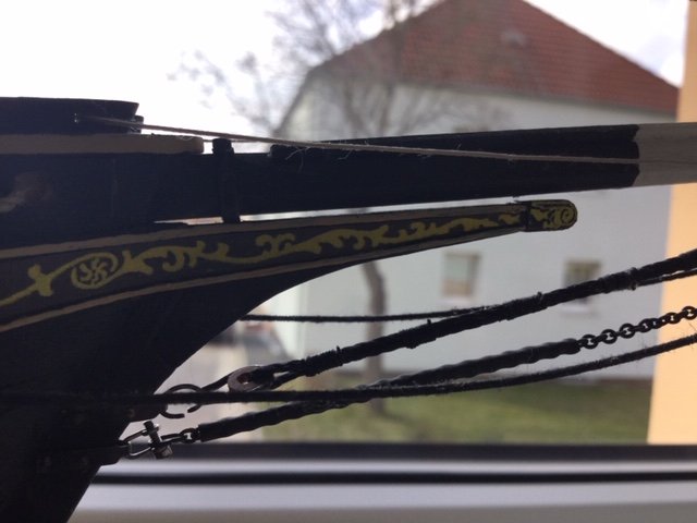
There is a gap of about 1mm between the bowsprit and the cutwater.
The bowsprit does not rest on the cutwater.The underside of the retaining bracket for the bowsprit is still in between.
Your Emma C. Berry looks good.
Michael
Son of a gun. Thank you!
-
After reviewing other build logs and looking at the covering boards, I realized that the king plank does need to be higher such that its bottom surface is level with the top edge of the stem. The covering boards wrap around the end of the king plank and extend up the stem a ways.
.jpg.12d90385eed28edf4e7c7d9aa19fd5c0.jpg)
I don't quite understand this; I thought the bowsprit was meant to rest directly on the cutwater. Since I haven't shaped the bowsprit yet, maybe this will become clear later on, or perhaps one of you who have been here already could provide some insight.
Anyway, it appears that I have some rework to do!
-
The last of 14 pairs of lodging knees have been installed and the frame ends sanded flush to the beams and knees, bringing an end to the framing phase of construction.
.jpg.cef68e37ff8bfd3cba2a4798939c6d83.jpg)
.jpg.2edd9f8563b23cbcff15afb51b43c706.jpg)
Most of the knees were straightforward until I got to the pair at the bow. This was another "If only I knew then what I know now" moment. I suspected the clamps landed too far up the stem but I didn't realize the effect this would have on the knees in that area. There was no way the 1/8" thick knees would fit under the king plank without lifting it above the top surface of the stem - way above. I had to thin the knees from 1/8" at the first beam to almost nothing at the forward ends.
.jpg.391fd97cd7547379aa224e496a9bad5c.jpg)
I should have taken more care with the placement of the clamps in this area.
Edit: It looks like I messed this up; the king plank should be higher. See next post.
A couple more views with the king plank, bowsprit bitt, and (yet to be worked) mast and bowsprit in place.
.jpg.c937bdaf161997bdcba4825ada8908ef.jpg)
.jpg.7ff8e0afd597ba5b04dcacf4964d090b.jpg)
Now it's time to break out the covering boards and see if those stanchions fall in convenient place among the frames.
-
The tricky transom area, and everything else, has come out really well. Very glad to see that!
-
Thanks, Will. It's never too late for a suggestion about a useful tool. I'll follow your ECB build with interest.
-
I am well into the lodging knees. I intend to install all of them even though half will be covered up. This post describes the process I've developed, in case it might be helpful.
I first check the space between the frames shown in the plans against the actual space in the model. It is usually very close, but in this case the model measurement was about 1/16" wider (a known issue, see previous post). I trace the shape of the part, and this time, the actual width (solid line) as well as plan width (dotted).
.jpg.4d204805ea9393759b66304416ee9435.jpg)
I trim the tracing and offer it up to the model:
.jpg.9191079240a1884ac5854a9c2fbb67dc.jpg)
I put a light coat of dilute white glue on the 3/4"x1/8" basswood strip and apply the tracing, with the long edge on the edge of the strip.
.jpg.1f48666141662228b6455a32b7295d0c.jpg)
Once the glue has dried, I cut out the curved area with a coping saw - close to but not on the line.
.jpg.59f69c613a02cffc7cde56cb26ea769c.jpg)
The result of this operation tends to be a ragged mess. I finish shaping the piece on a makeshift setup using a Dremel sanding drum in my drill press. This does a nice job of making a smooth curve with right-angle edges.
.jpg.77d8e256c018ed82d96bd3ef5b2013fd.jpg)
Next, I cut the sides. This requires holding the strip in the miter box at an odd angle and can be difficult. It's the first time I've wished for a mini table saw with a really good miter gauge.
.jpg.012f97bedde35907d4b8c89fb7dee3e6.jpg)
I trial fit the piece on both sides of the model. Usually it requires a bit of sanding to get it down to the correct width, but in this case it was almost too loose on the starboard side and much too loose on the port. So this piece is destined for starboard.
.jpg.c8207a92fa6981353b5fc011efe40578.jpg)
To make the piece for the other side, I use this piece as a template, reusing the cut in the strip since it is at the correct angle.
.jpg.be252b2a8041e0af2ccf0bba91f1cc1a.jpg)
I repeat the cutting and shaping, making sure to take into account any differences in width, then mark and scribe the joint lines. Once everything fits correctly, I glue in the pieces with PVA.
.jpg.36fb272c29848504d3c238b8907ee440.jpg)
And there we have it. I'm not particularly pleased with the fit of the starboard piece, and will fill the slight gaps at the edges. It's worth while to cut the pieces just over width and sand to fit; however, the only piece I had to discard was one that I cut too far over width, and messed up while sanding.
I have now installed five pairs of these things, in addition to the knees surrounding the mast partner which I did previously. There are eight pairs to go, plus whatever is supposed to happen at the bow. Tedious, but rewarding when I get them right.
Thanks for the likes, comments and suggestions,
-
Some progress to relate - doesn't look like much but it still takes time. I drilled the holes that flood the live well in the planks beneath the well. As is usually the case, I refined my technique as I went along, but this is one time I really wish I could have a do-over.
.jpg.15cbd0d2d3df4ec4cd0233918ac31a33.jpg)
Can you tell where I started? Second group from the left. I can clean it up some, and the holes won't stand out that much against the dark anti-fouling paint. Next, I switched to the starboard, which I plan to leave mostly open, and added partial planks (I call them stub planks) at the stern and bow.
.jpg.732fe9e8cf876466c2c73181cf7b0463.jpg)
.jpg.702e86d46b31888c435d1e72e029d898.jpg)
I plan to run stub planks to the entire transom and stem, with a similar treatment in the upper few strakes to create a large, sort of oval-ish window to the interior.
At this point I have a question: How do you trim the planks that overhang the transom? The goal is to get a cut that is perfectly flush to the transom's face and has a sharp edge, without damaging the transom over much. I purposely did not install the oval trim ring on the transom yet to avoid damaging it during this operation. I have a razor saw and a number of Xacto blades at my disposal, and I realize that I need to use a hard, flat sanding block when sanding the plank ends to avoid rounding off that edge.
While installing the stub planks at the bow, I realized that they were not going anywhere near as far up the stem as the same number of planks on the port side. In my previous post I noted that I had thought the planks weren't far enough up the stem and added extra-wide ones to "correct" the error. Now, after much thought, I decided the error wasn't an error and that my measurements and planks on the stub-plank side were correct. So I excised and replaced the top three planks on the port side; now it matches the starboard exactly.
.jpg.f2a6e6adbd387cf16ef0f18647e8f173.jpg)
.jpg.ed06fc500767c762e0653801f9af9b6b.jpg)
At this point I'm done with planking for the time being, so I need to install the deck framing. Since I try to do as much as I can with the parts off the ship, I decided to make up the various bits that attach to the frames. The cabin coaming is made of 1/8" square stock with a 1/16" square rabbet cut into its length. Turangi did this quite beautifully with his scalpel but I decided on a different approach: a router bit mounted in my drill press and a guide.
.jpg.7a9ff21d071e47ef8e275fcacf8ccd21.jpg)
This eventually produced acceptable results but only after I tore up some stock figuring out how to feed it. A router bit is a pretty brutal tool to use on a small basswood strip. Anyway, here are the collected coamings and the rudder stock pad that I made:
.jpg.606e1992abe527ee5e5e1c67d2fd30cd.jpg)
I trial-fit them and noticed that the king plank, which should abut the forward hatch coaming, comes up about 1/16" short.
.jpg.2fe480e79e71ab4cd8bc92744a2a54ec.jpg)
I can't move the king plank because it establishes the mast angle and its forward end is pretty much where it has to be. I can't move the hatch frame assembly - which I think is slightly aft of its proper location - because the live well has it locked in place. So I'll need to make another coaming that fills the gap, which I'll defer until the deck framing and king plank are firmly installed. Another case of ready, fire, aim...
Thanks for the likes and the comments!
-
1 hour ago, CDW said:
I thought about the same thing....surrounded by fuel. Yikes!
At least they had fuel cells. That was a huge safety advance in - the '70's? I recall some of the awful fires in F1 prior to that - mostly a thing of the past, now. When Romain Grosjean's car went up in flames last year, it was a complete shock to everyone
- mtaylor, Old Collingwood, lmagna and 5 others
-
 8
8
-
-
10 hours ago, turangi said:
One suggestion I would offer that deviates from the instructions is to install the bulwark stanchions before planking the deck. Once the deck is planked it is just by guess and by golly to secure the stanchions by applying glue through the small covering board holes without being able to see where the glue is actually landing.
Good point. I think I will also install the stanchions as soon as I've added enough hull planks (maybe just one) under the sheer plank to position them, so I can get behind the planks from below. Not there yet, but getting closer.
-
Planking the port side proceeds. I've finished eight strakes - the "C" belt plus two, and enough to close up the bottom of the live well on that side. These three photos are prior to sanding.
.jpg.1e18423a0c6e420947bee5d9b9159b03.jpg)
The plans call for the three lowest planks to be nibbed into the planks above them at the stern. I got better at it as I went along.
.jpg.b546efb07450a3a65cf72231b1287082.jpg)
At the stem, I think I over-tapered the first few planks and tried to make up for it with a few exotically shaped planks - worked out reasonably well, but the whole area is a bit rough. You can also see where I've added a narrow shim to a frame, one of several requiring this treatment.
.jpg.27825156ef62c2037c52df46f7ee1ae3.jpg)
After rough sanding, things looked better.
.jpg.9fea960339c72130b7d2f6ea53787715.jpg)
And the interior view, showing where the planks that form the bottom of the live well will be painted:
.jpg.a13199148938a93478c32dee1f9d18ff.jpg)
I'm pretty pleased with the way this has gone. My prior planking experience was with widely spaced, thin bulkheads; planking over frames seems a lot easier. I haven't used any edge gluing except at the stem and transom. Prior to installing the frames, I sanded bevels per the plans and this made fairing go quickly, more touch-up and identifying frames needing shims than anything. The planking layout diagram makes it easy to line the hull, and if I carefully taper the planks to fit the lines, they pretty much fall into place. A very satisfying experience so far.
I'll take a look at the starboard side to try to get an idea of how much planking I want to do there. I am pretty sure that I won't install any planks above the garboard strake in the area of the live well, but I'll probably add some planks at the bow and stern. The rest of the planking will have to wait until the deck framing and cover boards have been installed.
-
On 1/29/2021 at 10:06 AM, ahb26 said:
I cut the rabbet - a first for me. The middle section along the keel requires a rolling bevel that I had trouble getting my mind around. I suspect the rabbet may be troublesome when I get to planking, a long time from now.
.jpg.808cfcd46a342cadc8b78cdd6a305faa.jpg)
Truer words were never written. I decided to plank the lower section of the hull so that I could paint the inside faces of the planks where they enclose the live well. I lined off the lower planking band on the port side (which will be fully planked) and started in on the garboard plank. I quickly discovered that the rabbet on that side was cut too low on the keel. I'll have to fill it in.
.jpg.eed9be4abcd1ed77d8ca562d1e212aae.jpg)
On the starboard side, I did better but still not perfect.
.jpg.dbfb6358996dbd05566447b931da8843.jpg)
In both cases I needed to employ Chuck's edge bending technique near the aft end of the plank.
.jpg.8777d050f0abd95383e304abc65b3304.jpg)
One positive is that I have gained a better understanding of the planking process. I knew there were various techniques - lining, tapering, edge bending, spiling - but I didn't have a good grasp of when or even how to use them. I reviewed Chuck's videos, which explained a lot. The Model Shipways instructions have a good explanation of the process, and the plans include both a hull planking profile (view from the side) and hull planking layout indicating the width of each plank on each frame. The plans also indicate where the three planking belts should be placed. I learned how to transfer dimensions from the layout diagram to the frames (using my great-grandfather's dividers) and got a sense of how they taper. It's the next best thing to having an experienced modeler at your side.
Now all I have to do is execute!
-
I finished the remaining beam assemblies but have not yet installed them - here they are just set in place:
.jpg.3970108a59a2204d387515f45e40f24f.jpg)
I'm pleased to say that all the assemblies, which were glued up on a flat surface, sit on the clamps with no rocking.
April Fools Day came a month early. When I made up the beams for the cabin opening assembly, I marked the mortise locations on one beam and transferred the marks to the opposite beam, as I had done with previous assemblies. But when I dry-fit the parts on the plan, I got a surprise:
.jpg.255bfad5b95ec656b5000af097c331ca.jpg)
Turns out the cabin is 1/8" narrower at the aft edge. Fortunately I hadn't trimmed the beam ends and was able to move one of the mortises over to the correct spot with the aid of a dutchman:
.jpg.b76a051d4a828a4e5346d35e684f32c3.jpg)
(Funny term, that. I had to look it up. I hope folks from The Netherlands are not offended.)
The last beam assembly surrounds the stock opening and will eventually be tied to the aftmost beam, glued to the transom, with two carlings.
.jpg.5e9c3a594a77bca6b7a4ceec7cce4b31.jpg)
Working on this model has really improved my ability to make parts like these with a higher degree of precision. It's also taught me to assume nothing and look at the plans before cutting anything - a variation on "measure twice, cut once."
Thanks for the likes and for your continued interest.
-
On 2/26/2021 at 10:18 PM, turangi said:
Beautiful and meticulous work! I am a couple of years ahead of you in terms of trips around the sun so I tend to take the quick and dirty approach.
Quick, possibly - dirty, not! Thanks to all for the likes and compliments.
I moved on to the deck framing that supports the mast, king plank, bowsprit pawl bitt, and bowsprit. The piece that the mast goes through - mast partner? - is 1/8" thick while the beams are 5/32" and slightly cambered. I cut the mortises in the beams and set up everything on a very flat board, with two short 1/16" thick pieces under the mast partner, resulting in the partner being slightly recessed below the surface of the beams. The two lodging knees serve to keep the beams parallel; they aren't glued in at this point.
.jpg.bfdb7ee138a35cfdb911a475a0d43316.jpg)
Once that set, I glued in the lodging knees using the same setup.
.jpg.103784f2a6ba8afa14f9b4ec67a7c1d3.jpg)
Now I could work out the mast position and also check that the king plank was correct. The mast's rake is shown in this photo by its angle with the frame, which is supposedly vertical. By eyeball it looked pretty close to the spec of 2-1/2 degrees - I later verified with a level that it is slightly larger, which I can adjust with a wedge at the base of the mast.
.jpg.4ce95b6093436170c42989eceb53d434.jpg)
At this point, the king plank wouldn't slide down the mast because the hole was too tight - I had to bevel it slightly.
Next I made the bowsprit pawl bit - twice, because the first one was a mess. The plans indicate that it's 5/32" thick above the deck, but the slot in the king plank is only 1/8", so a shoulder must be cut at deck level. Also, there is no 5/32" strip wood in the kit, so I had to cut the piece from scrap on a laser part sheet - fortunately, there's plenty of that. Here's the bitt in place with the bowsprit stock trial-fit:
.jpg.b870aa18381bfda220c3c6f2ae196d82.jpg)
Next up was the assembly of two beams that supports the bitt - more micro-carpentry. This is the glue-up, with accoutrements appropriate to the task:
.jpg.ce969ef89bfd159ea72eebfd01109870.jpg)
Note that these two beams were cut from a single laser-cut beam - there aren't enough laser-cut pieces supplied to use one for each beam.
At this point I did a lot of trial-fitting and fettling to get this assembly in the right place relative to the bitt slot in the king plank and also at the correct height. As mentioned in a previous post, I suspected that the clamps might be a bit high in this area and that proved to be the case. You may be able to see where I notched the clamps slightly under the frontmost beam.
Edit: This placement of the king plank is not correct - its lower surface should be level with the top of the stem. Here I have set it up so its upper surface is level with the top of the stem. See Post 33.
.jpg.2f51ff2455bd09e4d3c3aeb6940ba765.jpg)
One final trial assembly before I move on to the next task, and a check to make sure everything lines up...
.jpg.f6c3c7a8c509a07723b9e10e2c694bd2.jpg)
... and it does!
-
-
Time for an update. Interior outfitting is mostly done, just needing some trim and a lot of paint. I have committed to doing just the port side of the interior, leaving the starboard side open so the underlying structure can be viewed. These photos show the well and hatch deck framing set in place - they are not yet glued in.
.jpg.ed0cc12e2441d1701ad4ff10c5ff15e2.jpg)
One bunk is enough!
.jpg.654d77db04025dd516c144bc084132cf.jpg)
I painted the inside of the well, but not the frames underneath it yet.
.jpg.742e0f3251936924fcaa1292ffff0f22.jpg)
I decided to omit the ceiling from the forward section to keep the frames visible.
To dig into a few of the details... I set up the fore and aft sleepers for the cabin sole at the correct level, then tacked a couple of scrap pieces over them to act as references while installing the rest. (Thanks to craigb for this tip.)
.jpg.702c7f1247689b9f0978d05eec997d82.jpg)
I decided to build up the front panel of the bunk before installing it, and added a few fake drawers. I used a jig to glue the two panels at the correct angle.
.jpg.6656d105ec5032d332f731a2640a2c83.jpg)
.jpg.edb03704242b7d938da20c3b7d8e1476.jpg)
.jpg.2f29c69ae76777175983c650ebc5f03e.jpg)
.jpg.8db3bfa67cb23d97434e69055f344bd8.jpg)
There are three ladders, each at a different angle to the vertical. I scoured the logs for tips on ladder building but ended up devising my own version of one of the jigs I saw. It keeps the stiles precisely spaced and allows the rungs to be placed at the correct angle for that ladder, adjusted by sanding the block at the end of the alignment tool.
.jpg.bf7ab8ce29bf805829bce239d4e23f64.jpg)
.jpg.01e2352a15425ee21121e9029f0a2526.jpg)
.jpg.18a7523a7e750fd7c504d92b54b31271.jpg)
While all this was going on, I also managed to turn 70 years old - how the heck did that happen?
Once the interior work is finished, there are various directions I can go. I want to get back to building the remaining deck frame sections, especially the one that locates the mast. I am also considering planking the bottom band of the hull so that I can drill under the well and paint the inside of the planks with anti-fouling red, without having to work through the well hatch. The upper band of planking can't go on until the deck and covering boards are in place, but there's nothing preventing me from doing the lower band now (other than fear of planking, of course).
Thanks for looking in and for the likes.
-
Thanks, Grant. I was a technical writer in a former life and I do like to explain stuff, perhaps to excess.
As promised, a couple of photos of the finished well in place. I've left one side off - planning to omit a good part of the starboard planking to expose framing and cabin details.
.jpg.502172774b46b8529977e3c4246d199f.jpg)
.jpg.27f3969bd6bd4be20cf86b8f560b95e7.jpg)
The well will be painted with anti-fouling red inside. The plans call for it to be "oiled" on the outside - still thinking about how best to show that.
I'll probably install the forecastle and cabin soles next and think about how much of the ceiling I want to install. Time to study the logs again to see what ideas I can, um, borrow. I also have to organize paint. I have some that is appropriate, including a gray for the interior surfaces - others I will need to source.
-
With the frames in place, I started thinking about the interior. I quickly realized that much depends on the location of the well and so decided to build that first. I combed the build logs and studied the plans. Few logs contain construction details for the well, and the plans - they need a lot of studying. I think I have come up with a structure that is anatomically correct (although I wouldn't swear to it) and its construction was interesting to say the least.
Before the well can be built, enough of the deck framing must be built to locate the upper ends of the well's corner posts. Once I got the hang of cutting the tenons and dados that join the carlings to the beams, I quite enjoyed this exercise in miniature carpentry. For the carlings, I needed to cut 3/16" square stock to 5/32" - this did the trick:
.jpg.992d1a985c005d6200d0c5149e36078c.jpg)
I assembled enough to define the landing areas for the corner posts, and glued it up sitting on the frame to incorporate the sheer:
.jpg.3fe6b8a962aff005d9acfc21cb9b7cd8.jpg)
Next step was to construct the side and end bedlogs, which taken together form a tub upon which the well is built. The side bedlogs look like combs with fat teeth that fill the areas between the frames and seal to the hull planking. The end bedlogs attach to the frames in front of and behind the well.
.jpg.04cec4ea233465fc873207571b15cab3.jpg)
The Batman profile of one of the end bedlogs allows it to fit over its frame's "floor" piece. The pieces were then assembled without glue into the hull. I used a home-made tool to align each side bedlog with the landing area for the top of the corner posts on that side:
.jpg.f404e860abc28ddb53b9f2ca329c4dc7.jpg)
.jpg.0e1df0ea1a76d634701703015ae40abd.jpg)
After a lot of measurement, adjusting, and fettling, I glued the ends of the side bedlogs to the end bedlogs - but not to the frames. I was then able to lift out the resulting assembly (which I cleverly photographed upside down):
.jpg.5b426c4400e8a20509c6d2b0241becd3.jpg)
With the tub back in the hull, I cut and shaped the four corner posts. Each post runs from a frame to one the corners of the well's hatch, outside the hatch opening. This is where you really have to look at the plans. The posts run outside the end bedlogs and the outer edge of each post aligns with the inner face of the side bedlog. The top of the post is angled to fit into the corner of the beam and carling. Next, I glued a plank to each side bedlog, and when that had set, glued the post to the inside face of the plank, but not to the frame. Then I glued the topmost side plank on each side to its pair of posts:
.jpg.95d306f65d1432c6b19724ddb6ff5bab.jpg)
To complete a rigid structure, I glued temporary battens across the fore and aft sides of the posts.
.jpg.6bef3a937bf059584624787c9d2db590.jpg)
I sawed off the top ends of the posts and sanded them flush with the deck frames.
.jpg.1118b8c032e122ff5a8e3d2c38fc5a62.jpg)
I could then lift off the deck frame assembly...
.jpg.b5732ddaa51e92530098548767f0d1fa.jpg)
... and withdraw the well assembly from the hull.
.jpg.8fd408d3988c8e2bd5b94ea23034ecf7.jpg)
This will allow me to finish planking and paint the well without having to work around and through the hull frame. The next post will show the full planking.
I hope this explanation is reasonably clear and that it will help someone navigate this area in the future. I welcome comments and corrections!
- chris watton, yvesvidal, gjdale and 5 others
-
8
-
The instructions have you install the transom prior to the clamps, but a few logs recommend doing the clamps first and that's what I did. The process was relatively straightforward. The boards need to be tapered slightly aft of frame 17 since the area where they glue becomes progressively shorter. After some pondering, I decided that the tapering should all come from the bottom of the clamp and accordingly sliced them down. I soaked them and bent them against a line of pins inserted through the plan.
.jpg.af6c3b779705976033117683a4724e7c.jpg)
On each side, I offered up the plank to the inside of the frames and cut the bow end to lie flush against the stem, then checked the fit of the board to each frame. I had sanded the inside bevel on each frame prior to installation but this needed to be adjusted on some frames, using a very thin sanding stick between the plank and frame. In a few cases, the frame was too far out of line and I had to remove the cross brace to allow the frame to flex into place. One frame became detached during this process and I had to reglue it.
.jpg.e92d23b3305f4953a086b1ea4d0b783f.jpg)
Finally, I glued the clamps into place. The beam ends rest on the clamps and should be flush with the tops of the frames; I used a scrap piece of the correct thickness (5/32") to position the clamps as I glued. Mostly this was successful, but there is one area where the clamp is slightly too high and the beam and/or clamp will need to be adjusted accordingly.
.jpg.3f69dbd9b5aadb8ff799fcf303829d1b.jpg)
I have some old clothespins (darker) and bought a bag of new ones at the grocery store. They are a weak imitation of the old ones - don't make 'em like they used to - but got the job done. I used binder clips in a few critical areas. With the clamps safely installed, I stripped out most of the bracing, recorded the as-clamped frame heights for posterity, and turned to the transom.
The plans welcome the builder to scratch-build the transom but I opted to use the laser-cut piece. I scribed plank lines on both surfaces, then traced the bevel lines onto tracing paper. I glued the paper to each side of the transom in turn, using dilute white glue applied only to the bevel line area. I sanded up to the bevel line on the paper, then removed the paper - light sanding took care of the glue residue.
.jpg.745b5efd972f3610c9aefec5a62db2b6.jpg)
I was puzzled for a while about how to shape the little tab at the bottom of the transom. After reviewing the plans and looking at other logs, I decided that planks would run either side of the tab onto the beveled area of the transom, and flush with the surface of the tab. Sanding at the bevel line on the tab produced exactly this result.
.jpg.00f2a4033266090ab4e643023a02d63e.jpg)
Now comes the first major question of this project. When I trial-fit the transom to the horn timber, positioned so that the bottom planks run fair across the frames onto the transom bevel, I discovered that the top edge of the transom was 9/32" higher (relative to the base) than shown in the plans. The distance between the (projected) deck surface and the beveled edge of the transom (i.e., bottom of the cap rail) is 1/4" more than shown in the plans. I spent a long time trying to figure out why this was so, to no avail. Everything seems to be in the right place, the transom is the right size, yet there's this large difference. Other builders have noted issues fitting the cap rail in this area, and photos of other builds at this stage seem to show the transom on the high side. Eventually, I made a leap of faith that everything will work out and glued it in, which brings us up to date.
.jpg.8dd848ebb18acdd847cc10a35adc6bb5.jpg)
I've given some thought as to how much of the interior to leave exposed. I am tempted to leave almost all the planking (hull and deck) off one side, rather than the smaller area shown on the box picture. Inside, I could build the floor, bunks, live well etc. part way across the hull, but leave some off to reveal the framing underneath. I have some time to decide.
- yvesvidal, oneslim, Duanelaker and 1 other
-
4
-
A new (and welcome) year and a new task. I had previously sanded the bevels into frames 1-4 as noted in the plans, so I started with 1 and glued each pair in turn to the stem or deadwood. I was being careful but not always careful enough: some of these eventually had to be re-set for one reason or another.
.jpg.7ac8e8971922867e147058320f84b5c5.jpg)
Note that the spring clamps I used previously to secure the bridge to the building board have been replaced by hefty C clamps I purchased. The spring clamps were not up to the task. (You can also see the extensions I added to the bottom of the bridge to allow me to clamp the amidships frames.)
As I moved into the next set of frames, those that glue to the top of the keel, I opted to glue the two halves together before installing them. I did another dry fit to re-check height and width, decided on a width that would give me a good compromise between the two, and glued them to that width.
.jpg.8f64ecdec4f901f2c8e7a4f14305ea51.jpg)
I then glued on a cross-brace before removing them from the board, using dilute white glue. After installing each of these frames, I trial-fit the keelson so I could sand the middle of the frame if needed (mostly it wasn't).
.jpg.3e684a5ae9e073775bd490a5040ac39b.jpg)
Some builders have installed the frames with a minimum of bracing. I took the opposite approach. Wherever possible, I cross-braced the frame halves, ran longitudinal braces between the cross braces, and added several buttresses down to the building board. The resulting structure was very robust and stable.
.jpg.bfc1af2845967454c3d7a429cfcf0793.jpg)
I was careful not to add any bracing that would interfere with the eventual installation of the clamps. As I went, I updated my spreadsheet with the as-installed width and height of each frame. I eventually recorded the port and starboard heights separately since they weren't always identical. The photo also shows the keelson finally installed. I used wood glue where the keelson crossed most frames, but to ensure good contact I used CA at the midpoint and aft ends and applied pressure until the CA caught.
To install the final two frames, I had to modify the bridge to clear the rudder box and horn timbers. I notched the bottom of the bridge and added a stiffener to the top.
.jpg.cb17e0ea7796f6abd3964ca4b3109112.jpg)
I braced the frames by running struts to the top of the horn timbers - not particularly effective as it turned out.
.jpg.30a489bce6906150cf1156397ec98065.jpg)
At this point, I had captured the "installed" dimensions for all the frames. I spent some time working on the spreadsheet to create a heat map of sorts, making it easy to spot where dimensions were out of whack, and did some adjusting of heights.
.jpg.6d4c9bacb1687e9f432c66ee49216092.jpg)
I readily admit to being a bit obsessive about this! - but I think the data may still come in handy later.
- mek, Mirabell61 and Duanelaker
-
3
![IMG_2753[1].JPG](https://modelshipworld.com/uploads/monthly_2021_03/119523720_IMG_27531.JPG.f13d68b7e14edcfb5891396b24cd5be9.JPG)
Emma C Berry by ahb26 - FINISHED - Model Shipways - 1/32
in - Kit build logs for subjects built from 1851 - 1900
Posted
Yes. I enjoyed the process of building up the skeleton of the boat the same as the original, and want to see as much of it as possible. I'm not incorporating this model into a diorama so I don't need to make it look like a repair in progress. I plan to leave off most of the deck on that side as well.
No. In retrospect I wish I had used some sort of non-pigmented stain or dye to darken them slightly prior to construction, but it would be tough to do that now.
Thanks for looking in and for the comments and likes!