


ahb26
-
Posts
285 -
Joined
-
Last visited
Content Type
Profiles
Forums
Gallery
Events
Posts posted by ahb26
-
-
Hi Frank, sorry for the delay in responding. The fifth photo down in post 6 of this thread gives the best look at how I ended up doing the horn timber (also first photo of post 12 and the last one in post 17). Referring to your graphic, the "two aft edges" of the horn timber side units should be flush with the aft edge of the center unit - these three together form the mounting pad for the transom. That means you need to raise the side units, which in turn means that the lower edges of the side units will no longer be flush with the lower edge of the center unit. This forms a rabbet - the planks will run on either side of the lower edge of the center unit (see second photo of post 12). I agree that the instructions are confusing - it took me a long time and scrutiny of other logs to figure this out.
-
We now reach the first major modification to the kit. I have a lot of 1/8"x1/16" basswood left over from Emma C. Berry, where I only planked a little more than half the deck. I decided to use it to plank Yankee Hero's deck instead of using the supplied pre-cut sheet deck. I also wanted to crown the deck - the carved hull does not have a crown and it might be difficult to get the sheet deck to conform to a crowned shape in any case. My plan was to use some of the scrap from ECB to make up "false beams" that I could glue to the deck.
.jpg.4c9167a769a03e12e80df3d194aa443d.jpg)
This illustrates why one should never throw anything away. I also wanted to install a covering board around the edge of the deck, rather than taking the planking right to the edge. I planned to cut the covering board from the supplied sheet deck. The Roger Long plans include a detailed cross-section of the deck edge:
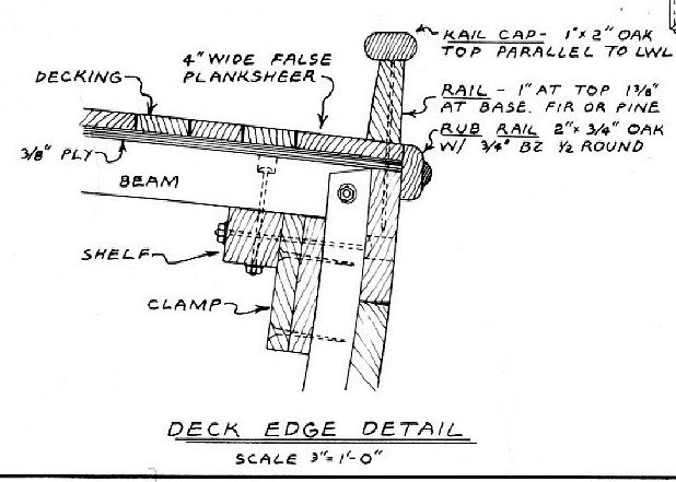
The part identified as the "false planksheer" is what I am calling the covering board.
The purpose of the locating pins in the cabin and hold is to keep the assembly precisely located during the process of adding the "false beams" and later the planking, while at the same time allowing the assembly to be removed. With the cabin and hold in place, I marked the location of the beams and set about cutting them from my scrap. This wasn't easy, as the thin pieces tended to break along the grain while cutting. I resorted to a good deal of sanding to get the shapes I wanted. Here, most of them are glued in place but not yet trimmed at the ends or faired.
.jpg.178c980146ba429e5f7ce1b4d0a6efc9.jpg)
I should point out that I glued 1/16" square strips to the bottoms of the cabin sides and front since they no longer were sitting on the deck.
I scribed the deck (not quite as wide as shown in the photo)...
.jpg.404897a2508a6212b5d5bcb0f5a859c3.jpg)
and cut it out. I left the center strip back to the mast to possibly serve as a king plank.
.jpg.92d435e3fcb9d4e0070fc940fd42db8c.jpg)
However, the mast hole in the plank didn't quite line up with the hole in the hull, so I removed the plank and cut a new one.
Finally, I glued the covering board to the deck and false beams, using CA. Some fettling was required but the edges of the board line up with the hull edges pretty well, and I will sand everything flush. I plan to cover the seam between the board and hull with a 1/8"x1/32" "rub rail" as shown in the deck edge detail.
.jpg.583554c1bfd8b2b6346b6d6efb8ec011.jpg)
To my relief, the hold-cabin assembly slips back in without difficulty.
.jpg.b97eed328d021fd4c62bb65927fab92b.jpg)
Now I need to finish painting the cabin, and work on the hull in preparation for painting.
-
Time for an update. The instructions call for building the hold and cabin assembly next, and this fit with my plans. It was a pretty straightforward process. I made sure things were square and glued the panels for the hold together with carpenter's glue.
.jpg.9b73b1494e3ce7439a6f9df76322049a.jpg)
The kit supplies cast fittings to represent the windows and shutters on the cabin sides. Instead of the fittings, I decided to cut the panels and build frames and shutters. I added "glass" cut from the clear plastic cover of the manual.
.jpg.4119934a18cb1ce27e9f9ac52b0984de.jpg)
To attach the cabin sides and front onto the cabin's back panel, which I had previously glued to the hold, I placed the deck on the hull and held it down with a rubber band to get the curvature correct, then positioned the side panels with the front, marked their positions on the deck, and glued. The resulting structure had no lateral rigidity, so I glued in a cross brace. The pins, made from 1/16" brass tube, were added to position the cabin-hold assembly precisely, for reasons that will be explained in the next post.
.jpg.6c66e7c338abd674593fe0c2a9d319c9.jpg)
-
4 hours ago, Frank L. said:
And, just now, I read your reply to my question. It seems as though we agree on the purpose of the strips. And I agree with you that the platform should be at deck level and i need to revise my cut-out template based on the frame profiles, as you have described.
With the nib stuff, I am leaving the keel tight to it, and will shim the prow against the jig to prevent forward slippage.
By the way, in my opinion, it seems risky to have a wooden live well, right in the middle of a vessel. So many possible points of leakage. No decent bilge pumps back then - I presume.
Just to be completely clear - the surface of the platform shouldn't be at deck level but somewhat below top of the lowest frame, to allow for installation of the clamps. The top-right photo in the historicshipmodels site shows this operation, and the photo two below it shows the clamps installed. The clamps are supposed to be glued to the frames a specific distance below the tops of the frames (it's in the instructions somewhere I think) such that when the beams rest on the clamps, their ends are at the same level as the tops of the adjacent frames. By the way, that's another benefit of the platform vs. the gantry setup provided in the kit - much easier to make sure the tops of the frames are at the correct level.
I agree that the live well seems a bit sketchy - not sure I would want to be asleep in the cabin in a heavy sea with that thing sloshing away next to me! Fortunately, the wells we build into the models don't have to be watertight. And how do you get the fish out of all the odd corners and pockets?
-
16 hours ago, Frank L. said:
Yes!! I too was confused about the strips extending out from each frame! I was going to ask the builder, but could not find his or her name on that site. Anyway, I scanned the blueprint into my computer and used AutoCAD to trace the hull profile with a reasonably smooth & sharp polyline. The tracing will be printed and used as a template to cut-out the elevated jig.
There is an email address on the builder's site - historicshipmodels@gmail.com - and his name is Greg Davis (in the About tab).
I was thinking some more about this. I think the strips are there to allow more precise placement of the frames. The opening in the elevated jig could be slightly oversize, with the strips overhanging the edge to the exact offset from the centerline required for each frame. You could tack the frame to the strip with easy-to-break white glue to keep the frame in place.
I'm not clear from your description how you developed the shape of the hull profile. If you scanned the "deck plan" in the bottom half of plans sheet 2, you will get incorrect results because your jig is not at deck level. What I think you need to do is use the "hull planking layout" in the upper right corner of sheet 2. The process would go something like this:
- Find the frame whose top (at the bottom of the covering board) is the smallest distance from the baseline (probably 12 or 13). Measure that dimension.
- Subtract enough from this dimension to allow for the installation of the clamps, plus a little more for comfort. The resulting dimension will be the distance of the top surface of your jig from the baseline (lowest point of the keel). On the planking layout diagram, draw a horizontal line at this distance from the baseline. Think of this line as representing a horizontal slice through the ship's framework.
- For each frame, measure the distance from the hull centerline to the intersection of the frame with that horizontal line.
- Now, when you set up the jig, use the dimension for each frame to set the location of the locating strips (port and starboard) for that frame. Let's say your jig is 8" wide and symmetrical. If a given frame's dimension is, say, 2-1/4", you can measure in from the edge of the jig 1-3/4" to set that strip.
- When you set up the jig, be sure to add the height of the baseline above the building board (about 1/2") to the dimension you found in step 2.
With regard to shimming the keel forward - I vaguely recall the issue and I think the builder was concerned that, with the keel all the way back, the stem didn't go all the way into the building jig. He wanted to eliminate the gap. More importantly, if the keel moved in the jig and you didn't notice, you could get inconsistencies. The lines on the building board are probably not needed with the elevated jig, but the lines on the keel must align correctly with the lines on the elevated jig, so it's important to make sure the keel can't move. By the way, that little nib will break off eventually. I glued in a separate piece, a bit longer than the original.
-
Hi Frank, and welcome to Model Ship World!
That looks like a very stable and accurate jig - only as accurate, of course, as the construction and placement of the jig. It locks all the frames in their exact locations without all the side- and cross-bracing I used with the MS arrangement. The builder is able to install the clamps in a very controlled and precise fashion - that's the key step in achieving a rigid frame. Determining the exact shape of the jig's opening might be a bit tricky, but I think the plans supplied with the kit have sufficient information to make it possible. I'll be interested to see how you make out with this approach.
One concern is that the jig might make it more difficult to work down around the keel. I also don't understand why the builder glued strips of wood onto the jig extending out from each frame location - not sure what purpose these serve. But the work looks very fine.
-
And so we begin. The first step is to shape the bow and stern to match the supplied templates. I found no issues at the stern. The bow required a bit of sanding but was generally close to the template. I also checked the deck against the top surface of the hull, and found (as others have) that the deck was too long at the stern - better that than too short! Near the bow, the deck was slightly smaller than the outline of the hull; I made a mental note to sand away the excess when I get to the sanding stage.
At this point I should mention that I initially planned to plank over the hull with left-over planking from Emma C. Berry. I thought about this a lot and eventually abandoned the idea: it seemed it would be difficult to do properly and was likely as not to end in tears.
Once the bow and stern shapes are correct, the next step is to establish the "center plane," essentially a line from the center points at the tops of the bow and stern down the stem and stern and along the keel. The kit provides a clever way to do this that worked well. Following this, lines are drawn either side of the center plane to mark the edges of the 1/8" thick stem, keel, and sternpost. This photo shows the lines marked, clearly off-center from the pre-carved hull. The plans note this possibility. Following the instructions will ensure that the center plane is at right angles to the top of the hull, which is what matters.
.jpg.2db31b3fff1cd1709620dc6d358aefdd.jpg)
In the photo, I've started to remove wood around the stern. I wouldn't call it "carving" at this point, more like "hacking" as I learned how to use the knives. Pretty much all of the shaping was done with the two blades shown. At first I thought I should get a rotary tool for the job, but in retrospect I'm glad I didn't. I probably would have made a mess of things. Once I learned to use them, the knives did the job pretty easily.
The kit plans do not include section lines or templates for the hull. I can understand that these might be a bit much for a novice builder, possibly causing more harm than good. But I would have liked to have them, if only to see if the finished hull is as symmetrical as it appears to be.
.jpg.98c7899c9401a715765216eef9768a7d.jpg)
Trial-fitting the stem to the bow - not sure how much shaping I had done at this point. It looks pretty good in the photo, turned out to be not quite so good when glued on later.
I used MH Ready Patch (of which I have an inexhaustible supply) to fill imperfections in the hull. Most were dings or chatter marks that came with the hull; a few were my doing. Generally speaking, the hull as supplied was in very good shape. After multiple iterations of fill-and-sand, I decided the hull was finally ready for a trial coat of primer.
.jpg.3cc888f7f8c9a6311af0d9a9f981221c.jpg)
I used Krylon "Rust Tough" primer, which I have on hand. (I may end up using this as the below-waterline hull color.) The pins were left in place so I wouldn't lose the location of the holes.
.jpg.fbff5a517183c73ae42ffd1fe8acf700.jpg)
I was generally pretty pleased with the results. After light sanding, there were a few remaining dings, and one area at the stern where I didn't like the shape I had created. I filled and sanded that.
.jpg.f126cca9a1f4c2ff5c1da57b63d91c4a.jpg)
The next step was to attache the stem, sternpost, and keel. I did the stem and sternpost first, holding the pieces in position with pins and applying pressure with rubber bands.
.jpg.2363eafbc16dba3eb1644980692dde1a.jpg)
Then the keel (after trimming it to length) and a section of the stem that didn't get enough glue the first time:
.jpg.0380051e3ad02311cbba0b1d75ff6350.jpg)
There were a few gaps between these pieces and the hull, mostly at the stem. I filled these and they await sanding.
.jpg.a3d8f6dbf2eeb7e93c0cb355590be94b.jpg)
In this photo, you can see the area I repaired previously under another coat of primer. I'm still not 100% happy with it and may revisit it.
There is still quite a lot to do before I paint the hull, but this is a good stopping point while I consider next moves.
-
History and research
Before I got too deep into the project, I read the manual's description of Yankee Hero's history and looked around on the web. The manual describes how numerous Eastport Pinkys, also called 'Quoddy Boats, were used to haul sardines from the fishing weirs to the processors in the northeast corner of Maine. Yankee Hero was distinguished only in that her builder created half-hull and rigged models, which survive and presumably form the basis of the kit. Searching on the Web, I couldn't find much additional information about Eastport Pinkys in general or Yankee Hero specifically, which leads me to believe that some cosmetic details, such as color scheme, might be speculative.
While I didn't find much about the boat as it was used in the 19th century, I did discover that reproductions have been created more recently for use as day sailors or camping boats. The WoodenBoat site offers plans for an Eastport Pinky. But the best find was a set of plans drawn by Roger Long in 1972, and later made available by him for unrestricted download at https://www.cruisingonstrider.us/27Pinky.htm. Here you can find lines, construction and rigging details, cabin layout - almost everything you would need to build the full-sized boat. Now, there's no guarantee that these plans are a faithful guide to how Yankee Hero, or any other Eastport Pinky of that era, might have appeared or been built. But they do illustrate opportunities to add details that were omitted in the novice-friendly kit. Some of those details (such as scuppers) would almost certainly have appeared on the original boat. Others might not have. I intend to incorporate details from the Roger Long plan that seem appropriate - or that catch my fancy, for that matter. I'd encourage anyone who builds this kit to at least have a look at these plans: they are fascinating.
-
After completing Emma C. Berry, I was looking around for a new project. I didn't seem to be in the right frame of mind to take on a big, long-duration build, especially one that required lots of intricate rigging, but I still wanted something that would present some new challenges. I chanced upon a completed Yankee Hero in the Gallery and it really caught my eye. This is one of BlueJacket's novice-level models and I hadn't previously paid it much attention, but after looking through a few logs, I realized that this model was a good fit for me for the following reasons:
- It rewarded careful work with a very attractive finished product - a chance for me to concentrate on fit and finish, not my strong points.
- Yankee Hero is a New England work boat - better still, a Maine work boat - and a nice companion piece to Emma C. Berry (same scale, same era, similar geography).
- I could get some experience carving a solid hull. (My inherited Joe Lane revenue cutter came to me with most of the hull work already done.)
- There were opportunities to add details to the basic kit. (More on this later.)
- The model is relatively small - easy to display.
- There are some excellent build logs. Forewarned is forearmed!
- Most of all, Yankee Hero just seemed like the right project for me now.
So I placed my order with BlueJacket, and on Feb. 3, it arrived on my porch.
.jpg.a5e175e97a4e9bb4929f10369978a3ac.jpg)
.jpg.000923759caf9b5f2b43b644e494fee6.jpg)
-
On 12/27/2021 at 9:22 PM, Dave_E said:
Beautiful! What’s next?
Thanks, Dave. That's a good question. I've been looking over various logs and kit offerings. Part of me would like to take on something more complex and challenging. There are a couple of three-masted schooner offerings that I find attractive, and I also like the Kate Cory for various reasons. But then I think - Three masts all the same! All that rigging, all those blocks and ratlines! Four little whaleboats! These kits are pitched at intermediate modelers but they are all major undertakings. On previous models - not ECB so much - I've found myself getting bogged down working my way through a frustrating patch, to the extent I have to force myself to get it done. More than once I've asked myself, Why am I doing this? (I suspect I'm not the only one.) I might opt for something less overwhelming, such as the MS New Bedford Whaleboat - it involves lots of fabrication, which I enjoy - or the BlueJacket Friendship Sloop, to replace one that I built decades ago and that was subsequently lost or stolen.
For now, anyway, I've offered to attempt a repair on a neighbor's ship model - nothing special, something he purchased. I also have a simple airplane kit, a P-39 Airacobra, to build in order to commemorate my father's cousin who was killed flying that plane in WW II. I'll continue to peruse build logs and keep an eye on the sales.
-
Thanks for the kind comments. Having your support along the way has been a great help.
I have already made a revision. I saw in another log a comment about the proper color for an anchor line - light, not black/tarred. Makes sense. I was none too fond of the black anchor line and the way it just sat on the deck. I assume it would be stored in a locker or something. So, I got rid of it. Makes that area much tidier.
.jpg.97c2ddf444da6c603872b8c5c7cf8615.jpg)
Now, about those rope hanks...
- BobG, Mirabell61, yvesvidal and 1 other
-
 4
4
-
A few final thoughts:
I decided against sails but I wanted to have all the running rigging possible without them. The instructions recommend how to arrange the jib and staysail halliards, downhauls and sheets when sails are not used, and I followed the recommendations. This was pretty low-stress rigging compared to my previous models - large scale and not that many lines. I wondered about the lack of ratlines, but somewhere in the plans or instructions I found a note that a crewman would climb up the mast hoops - pretty daunting if they were wet and/or greasy. All things considered, working on the ECB and her sister ships must not have been for the faint of heart.
I thoroughly enjoyed working on this kit. It was a great learning experience in two ways. First, I learned how the ship was built from the inside out, one step at a time - just as the original builders would have done it. That's why I left it as open as I did, to reveal the framing to viewers who may never have seen this type of construction. Second, it forced me to learn or refine skills at every turn. Even with all the laser-cut parts, a lot had to be scratch built - for example, all the deck framing. There was more metal work than I had encountered previously, and laying the deck with individual planks was a first. There were challenges at every turn, but nothing I couldn't handle - a very satisfying experience. The various ECB build logs helped enormously, and I thank everyone who has maintained a log and who dropped by with encouragement and suggestions.
I would recommend ECB to anyone who brings a moderate level of experience and would enjoy expanding their knowledge and skill set. One thing to understand at the outset is that it's crucial to study the plans as well as reading the instructions. Most everything you need to know is in the plans. They are masterpieces of information delivery.
In terms of enjoyable hours per dollar, it would be hard to beat this ECB.
-
-
6 hours ago, allanyed said:
Personally I do not agree that using white PVA on rigging is useless as I have never had an issue with it holding fast rigging seizings, knots and clinches on cleats, pins, etc. over the past 45 years. This includes one model that I built in the late '70s that has made numerous moves around the US over those years and is still in great condition. From comments here at MSW, CA may be OK for some things, but it seems that it is not such a good idea for rigging based on their experience.
I do wonder if the material of the rope being used makes a difference though in the type adhesive that works best in these situations.
I've used white glue without problems when rigging with cotton thread, but this stuff is nylon. I tried both white glue and PVA on it and it just didn't hold. Even something as simple as treating the line end to stiffen and reduce fraying failed miserably with white glue. I'd much rather have used dilute white glue but it was a no-go this time.
-
Welcome Jimmy. I found your build log yesterday and was amazed at the progress you have made in spite of difficulties. She looks great. I seem to favor small New England-built ships and Flying Fish is a beauty. I will follow your build with interest.
- JimmyK, mtaylor and Keith Black
-
3
-
On 11/20/2021 at 10:58 PM, turangi said:
A small suggestion, you may want to put a small bend in the middle of the horse to keep the boom centered when you tension the rigging. I didn't and wish I had.
Thanks for that! A very small bend did the trick.
I have finished everything I plan to do, although I still need to get a better base board. I have taken some informal photos which I will post soon, but I thought I would share one very useful hack first. As I mentioned previously, the supplied nylon line is very springy. It will happily untie itself from any knot or belay that isn't well secured. When I was belaying the various halyards to the mast cleats - access is pretty limited in there compared to elsewhere - it was very difficult to keep the turns on the cleat and especially to secure the belay by looping it on itself. Any relaxation of tension would immediately result in the line flying off the cleat, putting me back to square one.
I finally came up with tools and techniques that allowed me to get the initial turns on the cleat without relaxing tension, but the final loop was defeating me until I found a bit of scrap wood that had a nice wedge shape. With the line temporarily tensioned with a clamp hanging from it, I slid the wedge in under the cleat. The wedge then held the line in place while I completed the loop.
.jpg.cd89c79af5a5781bead8fbd57737a7ba.jpg)
I'm glad I pinned all the cleats to the mast, because if I hadn't, I surely would have knocked them off.
I also mentioned previously the need to use CA to secure seizings, knots and belays. The line is too slippery to hold on its own, and white glue is useless.
- Ryland Craze, gjdale, mek and 1 other
-
4
-
Grant, Yves, NiwotWill, turangi - thanks. The house seems a bit emptier but we're doing OK.
John - The "end bedlogs" comprise the four boards identified by arrows pointing to the lowest and uppermost. That dimension can be taken off the plans. You cut one piece to represent the four boards. The "side bedlogs", that look like combs, are seen end-on in the left-hand diagram on the plan - that gives you the height, which is roughly twice the thickness of the frames. They are cut to sit tightly between the end bedlogs.
I think I spent hours poring over the plans and photos of other ECB builds as I built the well. It's a tricky area. The photos in posts 9 and 11 should give you a good idea of how I put it together. Hope this helps!
-
It has been just over a year since I began this enterprise and a few weeks since my last post. Not much has been done on the model since that post. First we were away visiting relatives at Thanksgiving. When we returned, we discovered that our cat Kelly, whose appetite had been declining, had stopped eating altogether. After an X-ray and abdominal scan, the vet diagnosed probable lymphoma and prescribed a steroid, which helped her appetite and made her feel better. Shortly thereafter, though, her left hind leg went completely limp, followed this morning by her left foreleg. The vet said that the cancer was most likely into her spinal column, and we decided that the time had come to put her down. It's a sad thing that all pet stewards must go through - especially so in this case since Kelly was my special cat, the one that would snuggle up to me at bedtime. I will really miss her. Her brother Izzy is still with us and has been a comfort in a difficult time.
.jpg.cdbb302dfe86041b0ebc05fb69dbd695.jpg)
.jpg.9bde00e58f3604de231d8dcfcb1f27ef.jpg)
Always inquisitive.
Needless to say, my mind was not on ship modeling while this was going on. I did a little of this and that, but now I hope to get back to it and finish this off.
-
Before I finished the standing rigging, I made up the topping lift and the main sheet, leaving them unrigged to the boat for now. I finally built the main sheet horse and drilled the holes for it:
.jpg.db97209e72f63267e6cc8e53bef8c9cb.jpg)
It's not glued in yet, I'll wait until it's time to rig the sheet. I turned back to the standing rigging and I believe it's now done. I installed the sheer poles and made up running lights. I deviated a bit from the plans, making them more like what I discovered while researching the lights on Bowdoin:
.jpg.b97ad7d4bbc7883ff3d003cb7d49b3a4.jpg)
After some difficulties with the wire pulling through, I installed them on the shrouds. (This photo was taken after the topmast stays were in.)
.jpg.a88a0500ca12da861e78a2417cc84a6f.jpg)
I had been putting off the jib stay and bowsprit until there was no option other than to do it next. Turned out to be easier than I thought it would be.
.jpg.9b49a0d81980d2c730e42291e5013ded.jpg)
The heat shrink tubing on the bobstay worked well. With the bowsprit all set and the shrouds secured, I made up the three topmast stays and rigged them.
.jpg.43eab924af275bfe5a1da7786883bd5f.jpg)
.jpg.7689d018d6b0fe1b75a0ebe830d8c6e5.jpg)
.jpg.43aa0a4efe62b1378bc4c9967a5da9d8.jpg)
So it's on to running rigging, much of which has already been assembled off the boat. The end is in sight.
-
Beautiful job, very tidy work. I am working my way through the final stages of rigging - the end really is in sight. Kind of hard to believe.
-
On 10/27/2021 at 8:55 PM, turangi said:
Looking very nice, rigging is a challenge! I have been working on rigging my model and have found that all blocks and fittings are not needed if you are not making sails for the vessel. as an example, the Gaff topsail halyard may look a bit strange without a sail attached. Several models built without sails on this site do not have the fitting and block on the upper mast as it would a bit strange without a sail. I suppose you could attach the fitting and not rig it in anticipation of of sails being fitted during the rebuild of the vessel if that is what you are representing. There are other blocks, lines etc. that also might look out of place with no sails.
What I am representing... not a shipyard scene, more like a three-dimensional cutaway drawing, like those I used to admire in Road & Track. My goal is to show as much of how things are put together as possible. For the rigging, I am not planning sails, but I'll include all the lines I can manage without sails. The instructions say these lines would be tied or shackled to something. The topsail halyard is a good example.
I've been making slow progress but I have managed to build up the three primary halyards off the boat, ready to install when the time is right. The top block for the jib halyard is shown as rope-stropped with beckets on either end. It took me two or three days of experimentation and frustration to get it together.
.jpg.ead2c01104bd44e84a0224b9bc9b6634.jpg)
The nylon line is very springy and uncooperative, and white glue doesn't stick to it. I had to saturate the seizings with CA to get them to hold. Other blocks are iron-stropped and did not present such a problem - I have thin black wire that can be wrapped around the block twice and fashioned into beckets or hooks as needed.
I test-fit the throat and peak halyards to make sure everything was untangled and would hook into the ironwork properly.
.jpg.514590e49975c54115492759c42f3078.jpg)
Then I stored them away, along with the jib halyard, for safekeeping by hanging them from a handy cable
.jpg.9023104bd8d122b0c0df9a5be8971c4a.jpg)
I wanted to make all three halyards from the heaviest supplied manila line (.028") since it was closer to the plan specification (.023") than the next-lighter manila (.016"). However, there wasn't enough to do the three halyards and the main sheet, so I ended up using .016" for the jib halyard.
With these halyards more or less sorted, I turned to the shroud lanyards. The spec here is .020" and the closest line supplied line is black .021". I know there is some debate over whether lanyards should be black or manila so I made up one of each, using the .016" manila line. Decisions, decisions...
.jpg.f70618c43e7cc358b00744b887a7a3b9.jpg)
The photos of the real ECB show light-colored lanyards - the picture on the Model Shipways box has black. I will probably go with the manila, as the contrast with the stained deadeyes is nice and it's also easier to work with than the slightly heavier black line. But I'll sleep on it.
-
I've made some progress on the standing rigging. Previously, I've struggled with creating proper attachments of line to spars, eyes, blocks, deadeyes etc. so I wanted to make that a point of emphasis on this build. The instructions stress seizing lines rather than using knots ("knots are for shoelaces") so a-seizing I will go. However, I decided to forego serving the lines this time.
I started by placing the shrouds and jib stay around the masthead.
.jpg.26b06dcbb4c7a0197808e390555a8c2c.jpg)
The jib stay should be spliced, but I just seized it. The supplied line is nylon; white glue won't touch it, so the seizings are secured with CA.
I wanted to work on the deadeyes on the bench, rather than dangling in mid-air as I have in the past - much less frustration that way. I used a simple gauge to measure up to where the top of each deadeye should be on the shroud, and marked it with a tape flag.
.jpg.7c4e767f750fe7a0dc0c0368d0008848.jpg)
The plans show the shroud being crossed over itself at the top of the deadeye and secured with a seizing, although this is not done on the real ECB. I did a proof-of-concept using a short length of line and white thread.
.jpg.5d443fc75b872279f9d7ff054e82f734.jpg)
The "seizing" here is a single constrictor knot, but it gets the job done. (I have a love-hate relationship with knots in general and constrictor knots in particular. Sometimes I can tie one in seconds, other times it takes me 15 minutes to get it right. I'm improving ... slowly.)
I set up the actual shroud in a hemostat, forming a loop near the flag and slightly larger than the deadeye, then formed the knot in the space between the clamp and the flag.
.jpg.f862675ad975b45ec279e5579d61057e.jpg)
(Full disclosure: the knot in the photo turned out to be a failed knot.) I pulled the knot snug but not tight, then tightened the shroud around the deadeye, keeping the knot as close to the flag as possible. A final tug on the knot and then on the shroud finished the operation.
.jpg.1ba7fb2917fa408844a4e09dcf78e09c.jpg)
From this point, seizing the shroud to itself in three spots was relatively straightforward, although I did start each one with yet another constrictor knot.
.jpg.20d1d75b92628b760f2d345351072cb1.jpg)
Thankfully, the deadeyes came out even.
.jpg.1a7655aae10cb3907c293b42e053142e.jpg)
They will look better when stretched by the lanyards. However, I'm not ready to commit the mast to the hull yet; I want to do as much rigging as possible first. I'll work on blocks next.
-
On 10/17/2021 at 8:18 PM, turangi said:
My question is this: on an actual boat do you cut off the excess lanyard flush at the secured point or leave some excess for undoing the secured area and giving some extra purchase to readjust them?
I'm about to deal with these same issues. The plans (sheet 4) say "Cow hitch [the lanyard] to shroud here [arrow to point below sheer bar] then seize to shroud below deadeye [i.e., to lanyard(s)]." CraigB's ECB photos don't seem to show this (a bit hard to tell, but the end of the lanyard just seems to snake around one of the reeved portions down to the deck) and there are other aspects that disagree with the plans. You pays your money and you takes your choice, I guess!
-
The metalwork for the mast was completed earlier, so I started by building the trestletree and bolsters - twice.
.jpg.143f809be8f4a44823ca47ef8418124c.jpg)
Version 1.0 is on the left and after further review of the plans, I concluded it was incorrect. Version 2.0 is on the right.
For the mast hoops, I used a new blade and lots of patience to free them from the sheet and trim and sand the attachment points. I left the laser char remain, since I was planning to stain them dark anyway. Miracle of miracles, no breakage!
.jpg.8aecf916caae928184ea7fa9a3bdf2a5.jpg)
I made up the spreader and attached it to the mast and mast band with pins and liberal quantities of CA. It took me a couple of tries to get it right.
.jpg.0fe7b4cdcf06f6ded0c4731fc2504422.jpg)
.jpg.39262bfd55cfa79708f5e72896f3aa07.jpg)
It was hard to believe that I could drill through the mast cleats to insert pins, but harder to believe that the cleats would stay on the mast without pins. It turned out to be relatively straightforward. I drilled the cleats before attaching them to the mast, and drilled separate holes in the mast, which made it easy to position the cleats.
.jpg.fb4dba590ea46c76ddf98cf84dc01f3e.jpg)
Finally, everything was painted or touched up and a few additional fittings added, such as the jib halliard eyebolt and sister hooks.
.jpg.3dc51c4d0149dbea0a97adab3d1e614d.jpg)
.jpg.b821018fe284da556190a85bb7eb1a9a.jpg)
The unpainted parts of the mast were finished in two coats of Minwax PolyShades Classic Oak Satin, scuffed with fine steel wool after each coat. The result is possibly the finest finish I've ever applied to a piece of wood, better suited to a piece of fine furniture than to a rough-and-ready fishing vessel. The mast dowel seems to be some sort of hardwood, perhaps a fine-grained oak.
.jpg.7f760d05bc7e7b5ceff042d37eed13bb.jpg)
.jpg.793fca9b0b9cd3e97a06d2407415b23a.jpg)
.jpg.0f7f4d9118172daa0914220e6fae545f.jpg)
.jpg.bfea766a8fb46964e0b624c0a6853c06.jpg)
.jpg.e20ec68f53aa6571e330b6dc8ad05c5c.jpg)


Emma C Berry by ahb26 - FINISHED - Model Shipways - 1/32
in - Kit build logs for subjects built from 1851 - 1900
Posted
That looks right. Here is a crop from one of my high-res photos that gives a pretty good view of the assembly:
The strip along the edge of the horn timber where it attaches to the transom was added by me to help locate and secure the transom (there is a matching strip on the other side). This matches up very well with your diagram.