HOLIDAY DONATION DRIVE - SUPPORT MSW - DO YOUR PART TO KEEP THIS GREAT FORUM GOING! (Only 72 donations so far out of 49,000 members - Can we at least get 100? C'mon guys!)
×

Captain Slog
-
Posts
904 -
Joined
Content Type
Profiles
Forums
Gallery
Events
Everything posted by Captain Slog
-
 Hi Mick, Great (and fast) progress, looking forward to more. Cheers Slog
 -
Incredible work Grant. I have 3 ships boats I could send you to complete for me Cheers Slog
-
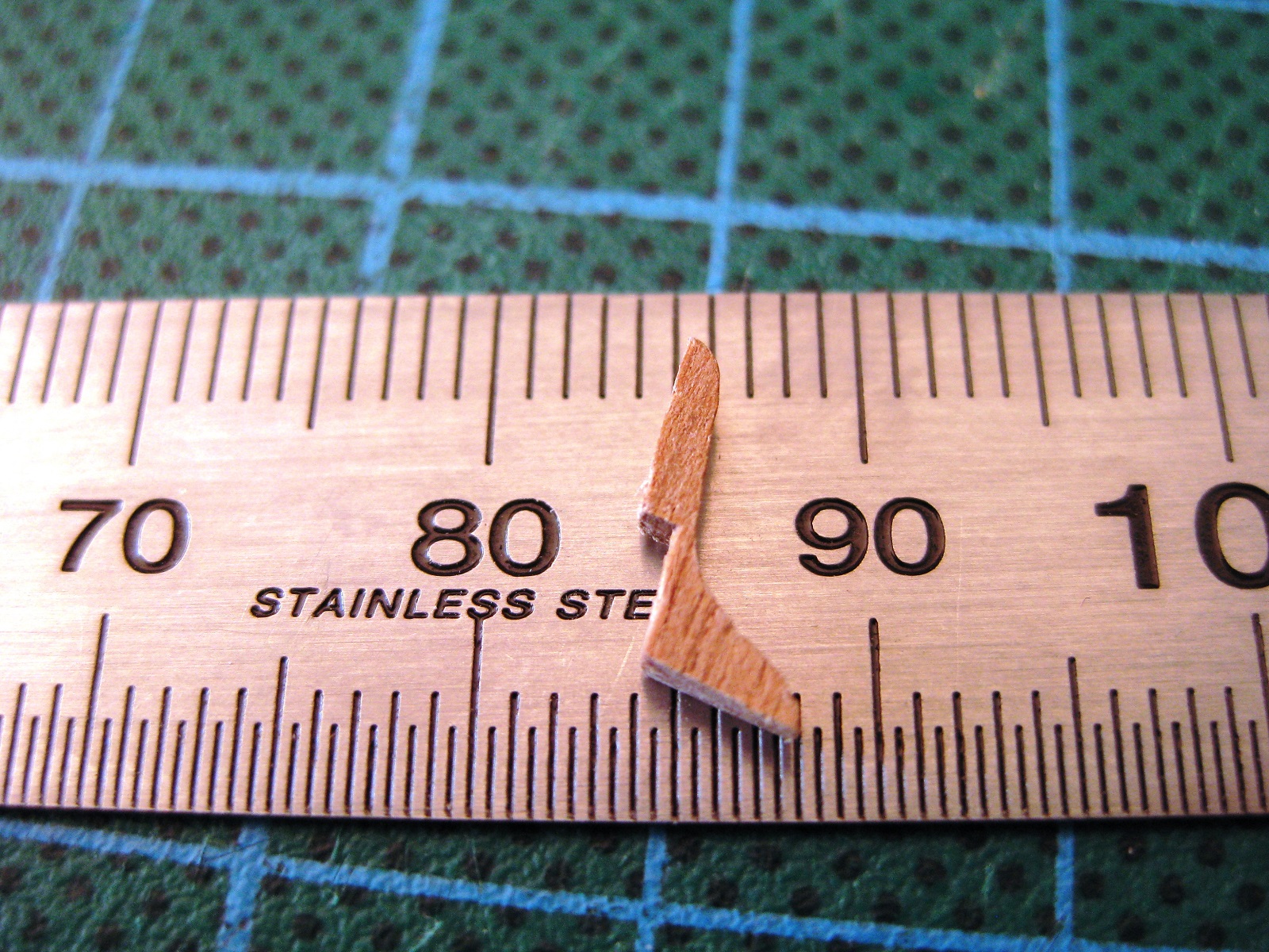
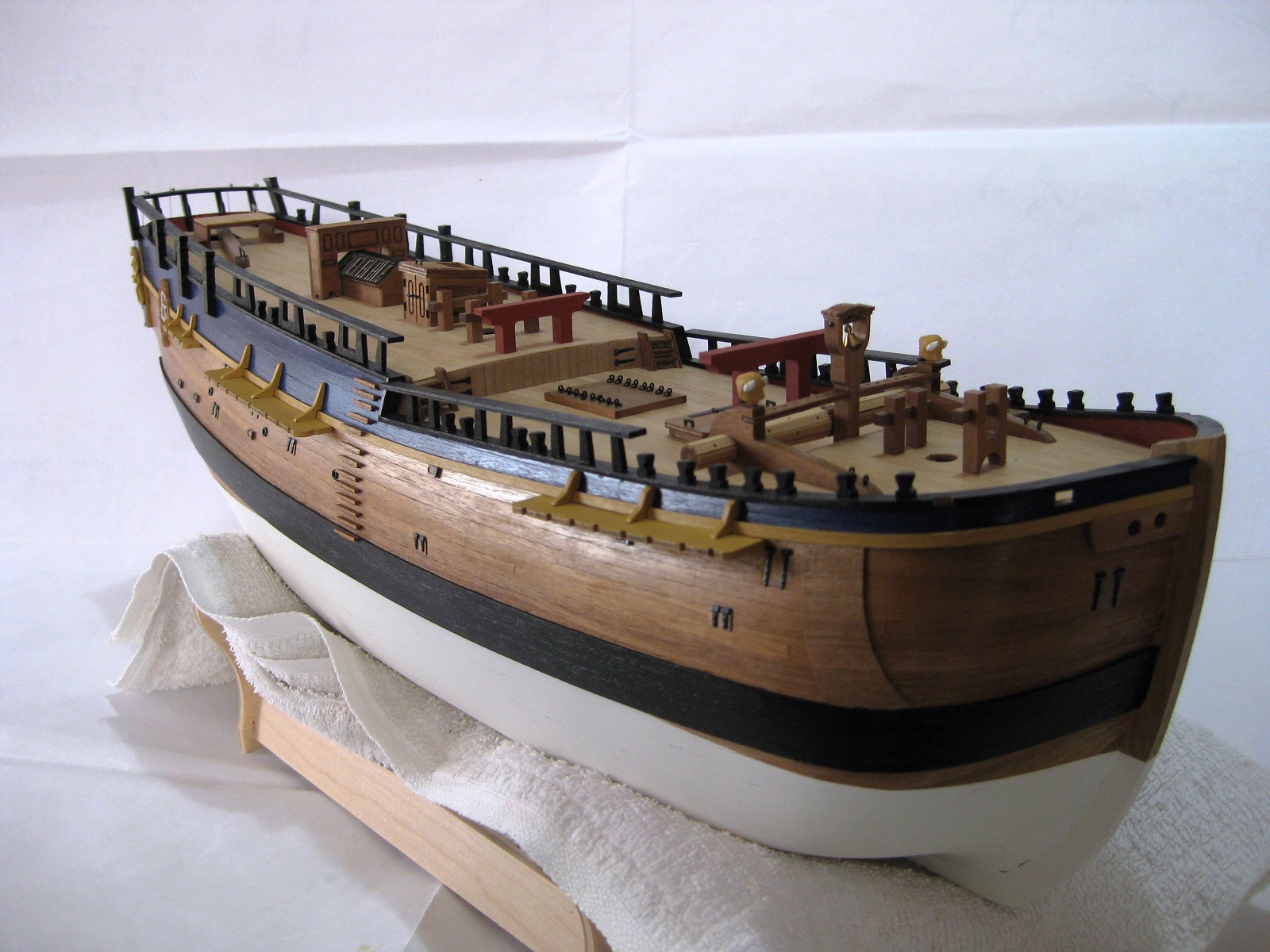
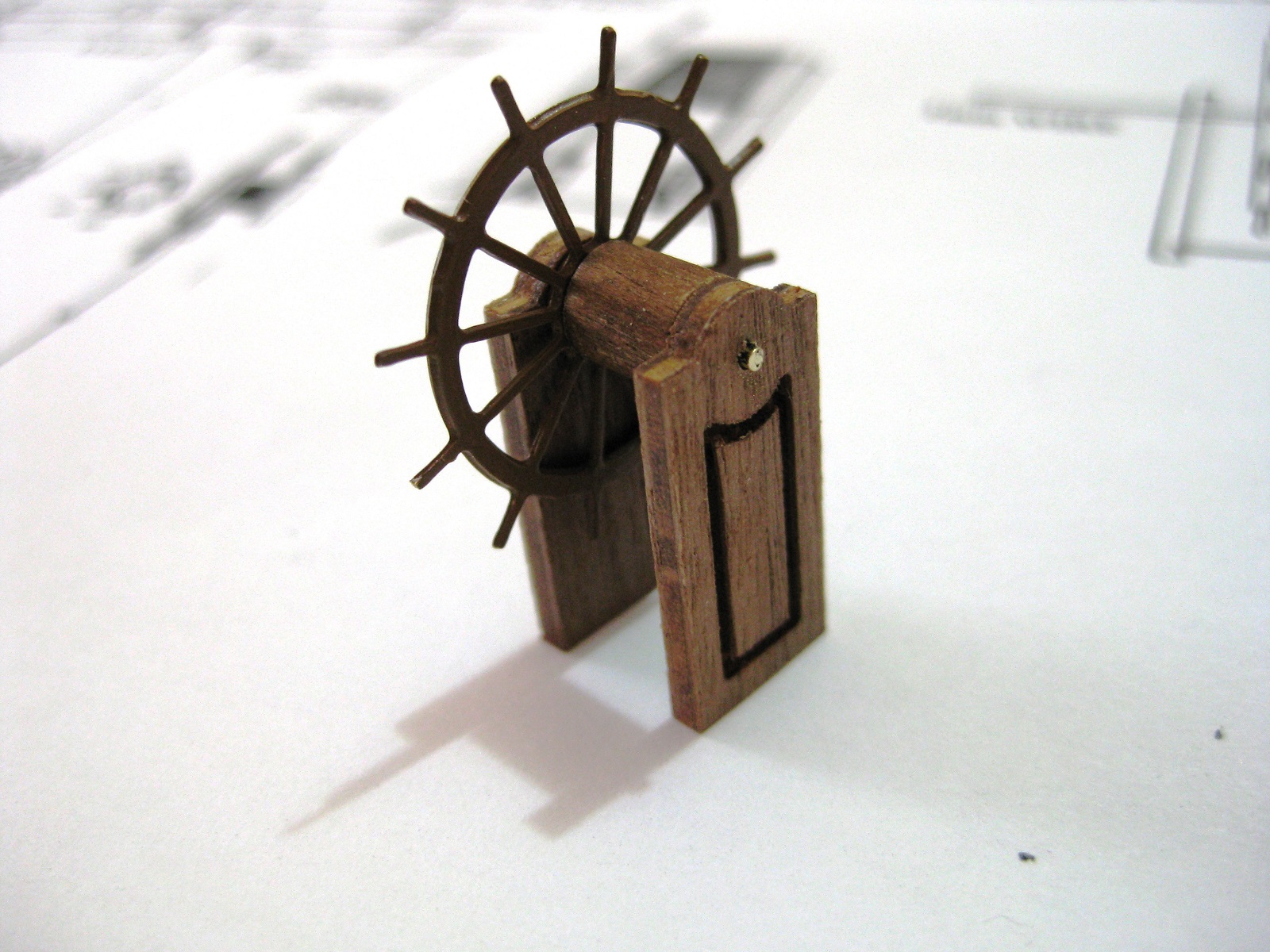
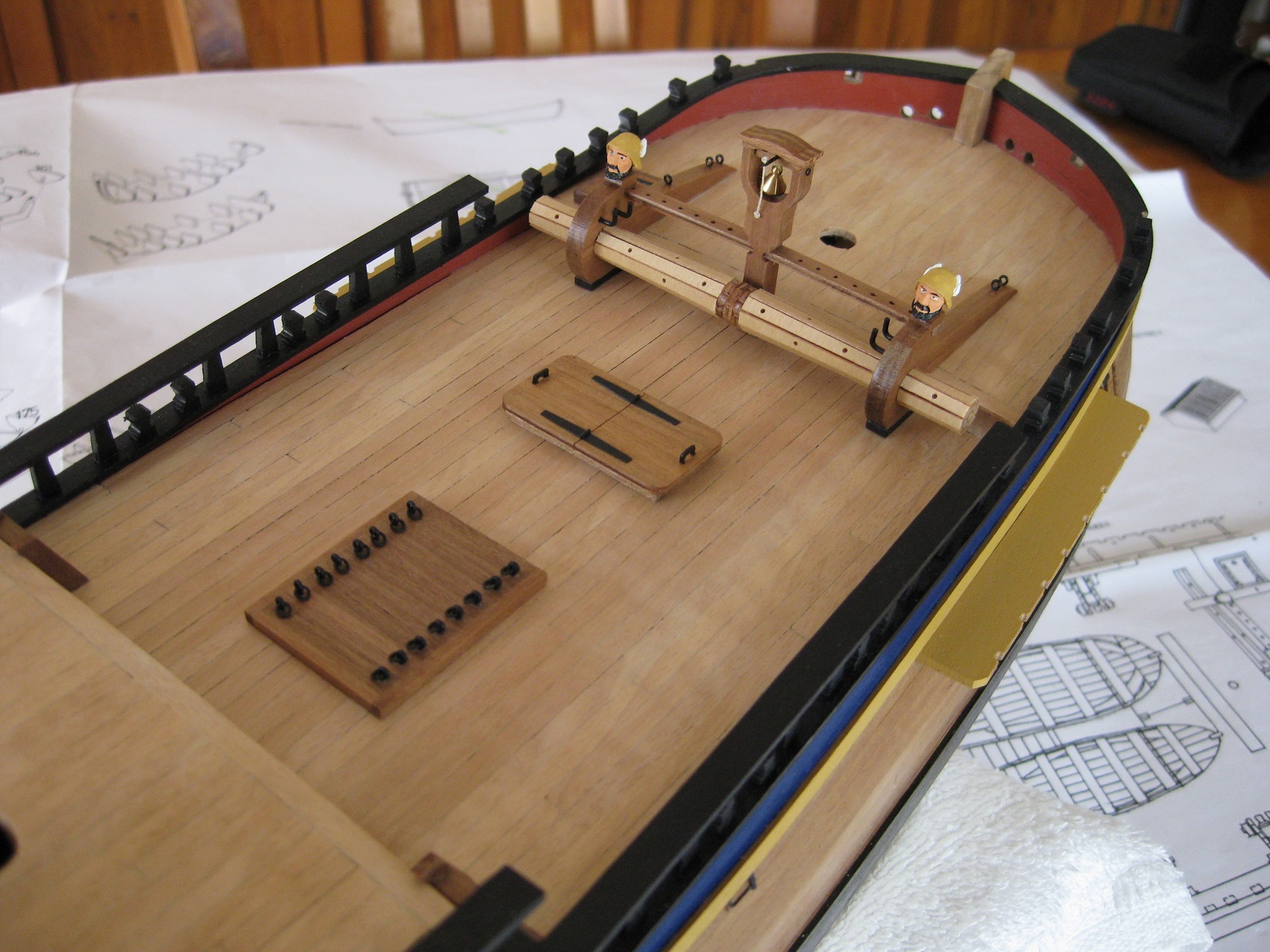
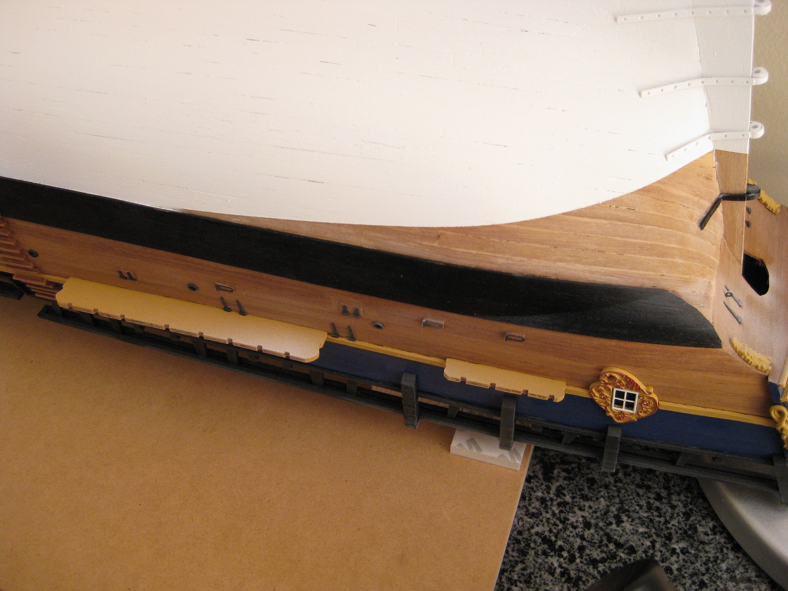
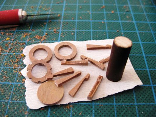
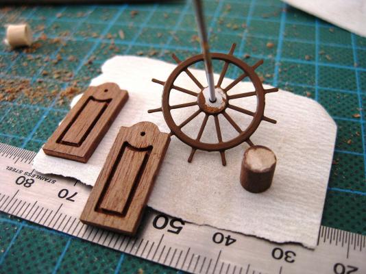
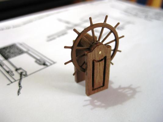
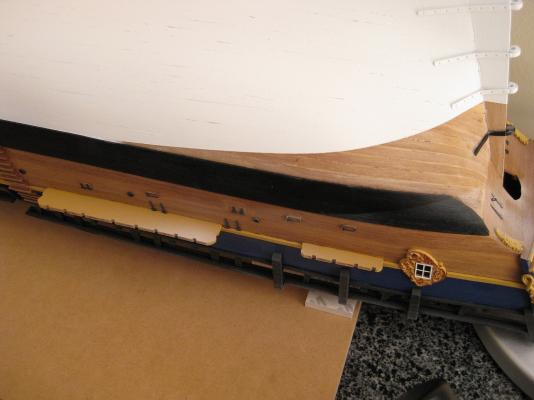
Hi All, A small amount of progress. As mentioned in my last post I decided to work on the channel supports which I didn't enjoy as found the little bits of walnut ply fiddley to cut around the shear strake. The channels, depending on their position also slope up or down and to get the supports to sit vertical a bevel had to be sanded on the bottom of each one. Initially I tried marking and cutting the support directly against the hull but couldn't get satisfactory results. The picture below shows how small the mizzen mast channel supports are and at one stage I only had approximately 0.5mm thickness left and it still wasn't fitted. I tried to make a notch in the shear strake so the support could still further back without removing more material off the already thin section. This didn't work either as I couldn't safely make the notches without fear of damaging the blue paintwork above so I needed to come up with another idea. I ended up filling in the notch in the shear strake and repainting and made another support using the originals as a template. I then glued some 0.5mm strip stock to the back edge of the mizzen mast channel supports to give them more depth for notching. I also used some business cards as templates to get the fit against the hull as this was easier to use then trying up the actual support each time. The shape of the template was then transferred to the piece once I was happy with the card fit. The supports were painted prior to fitting and then after marking thier position on the channels with Tamiya tape were glued on using CA. Next up was the capstan. After cutting out the parts from the walnut ply sheet and tidying up, I needed to make the barrel. This is made from 8mm dowel which I stained using the Admiralty Paints walnut stain. As the deck where the capstan sits slopes down from the stern to the mid deck I also measured and sanded the bottom on an angle so once placed on the deck the capstan sits vertically. I used PVA to assemble and then gave it a couple of coats of satin wipe-on poly The ships wheel followed. I cut out, cleaned up and varnished the 2 supports before fitting together. The ships wheel is a photo etch part which I sprayed with Skull white and then painted with Admiralty Paints brown paint. The barrel is from 6mm dowel, 6mm long which again I stained with walnut. It is all joined together with a piece of 1mm brass rod. I CA glued all the parts together but still need to sand the support bases so again it sits vertical to the sloping deck. Cheers Slog


-
Intro to Card Models Part VI: Building V108 - The Superstructure
Captain Slog replied to ccoyle's topic in Card and Paper Models
Hi Chris, Great series you are providing. The only problem is, it makes me want to get back to my Bismarck when I am on a role with my Endeavour. I voted to go the whole hog Cheers Slog -
Hi Adrieke, I found the Admiralty Red Ochre to be a lot darker and muted than expected but its grown on me now, but definitely a lot darker than the replica which you are replicating with your build. I also found the yellow ochre to be quite mustardy but again its grown on me LOL. Cheers Slog
-
Hi Bankie, You're off to a good start. Your deck looks very nice. Looking forward to seeing more. Cheers Slog
-
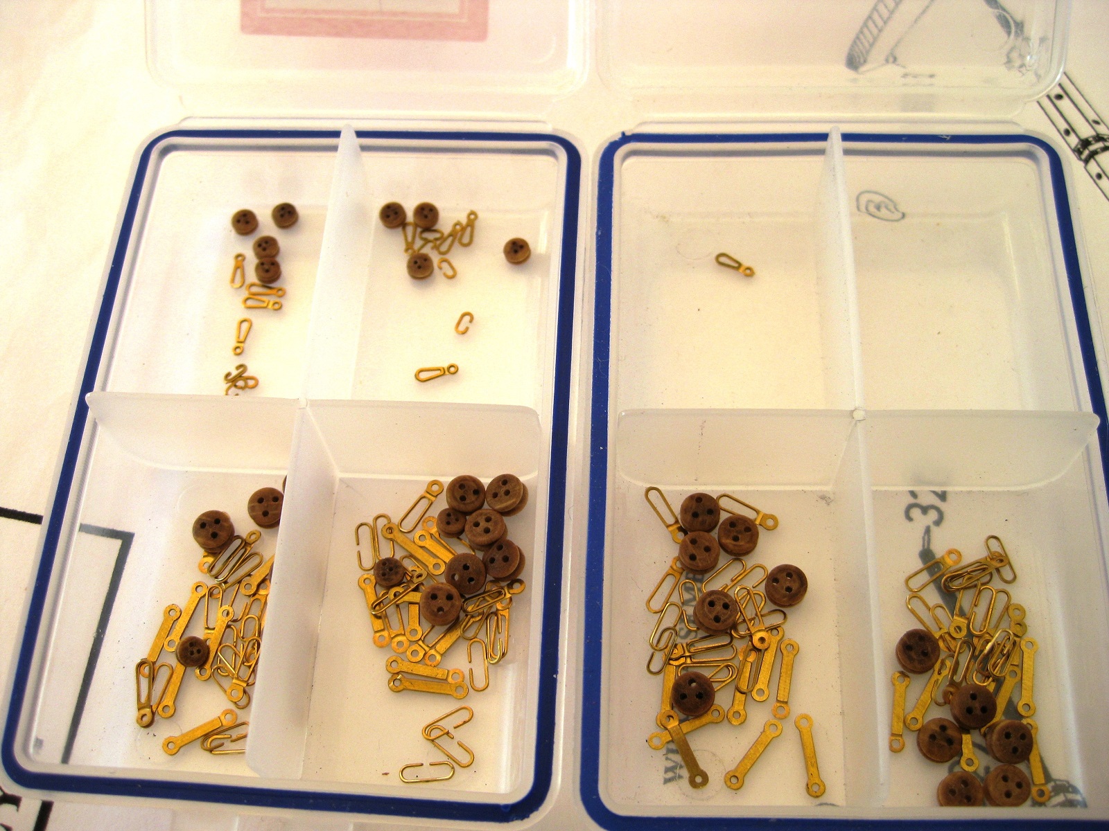
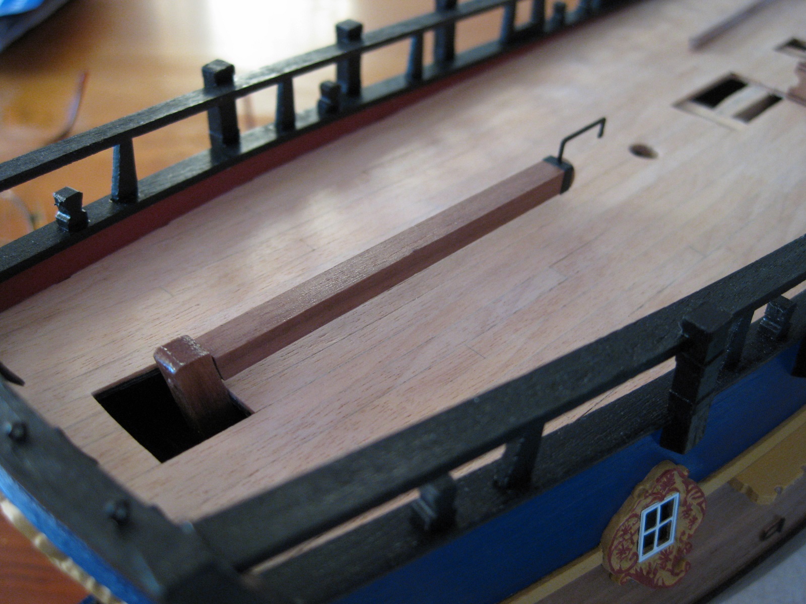
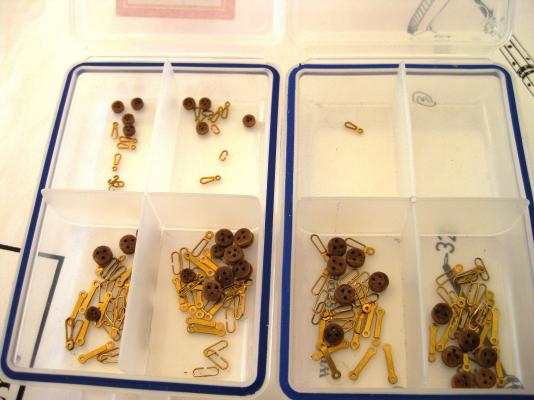
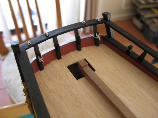
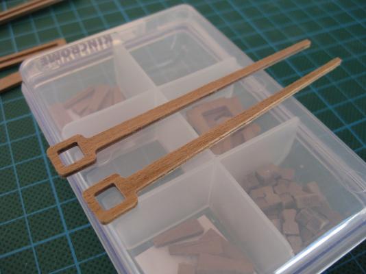
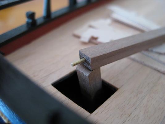
Hi Guys, Thanks for all the comments. Not much to report. Fixed the bitts and gallows in place. After determining their location from the plans I used short lengths of Tamiya tape to mark the positions on the deck. The bottom of each post was drilled and a length of 1mm brass rod glued in place. A corresponding hole was marked and drilled in to the deck and the rod and bottom of the post given a dab of CA glue and pushed into place. Next up is to finish the channels once and for all. From the plans I collected all the parts from the PE sheet needed for each channel and stored them in small containers until I could work on them. After fitting and gluing the chains together I got everything ready for spraying with Chaos Black. The chains were threaded on to a length of brass rod and the chain plates stuck down on to decorators tape, sticky side up. I have also started to fit the channel supports, which are 2mm walnut ply but found this tedious and so progress has been slow. Hopefully I will have made some progress on these to show next time. Cheers Slog


-
Hi David, Looking forward to following your build. Nice one winning the longboat. Cheers Slog
-
Hi Navyyeoman, I am no expert in coppering a hull as I have never done it before but the way I would calculate the area and therefore the number of plates needed would be to simplify the measurements. Firstly I would measure the overall length of the hull to be coppered (including the rudder) and then measure from the top of the coppering to the bottom of the keel to get the area of a simple rectangle then multiply this by 2 to get total area. Once I worked that out I would add 10% to foul ups and wastage then divide this by the area of a single plate to get the total number of plates needed. Don't know if this helps but that's how I would do it. Cheers Slog
-
Very nice Jeff, you should be very proud. Looking forward to following your Pickle build. I used to keep track of the time spent on my build, which I would record the date, what was done and for how long. Kept it up religiously until my computer detonated and lost it all including early build photos so don't bother now, but will again for my next build (and back up more!) Cheers Slog
-
Hi Kevin I don't think you have been shot as the messenger but I think the thread has gone off track slightly. I also don't believe that new mass production technologies will kill craftmanship. The thread I was following was about the design and construction process of a prototype for a mass produced KIT. If new mass production technologies can give us clean, crisp detailed mouldings, carvings or whatever instead of the usual blobs of metal then we as KIT builders can only benefit. If Chris pushes for the best method for the best carvings etc then that can only be a good thing...unless the additional cost pushes it outwith the reach of many. Craftmanship is associated with scratch builders who pick one ship and (typically!!!) only make one investing thousands of hours over, in some cases many years. Mass production doesn't come into it. He will carve each piece individually as needed and if he can't carve will learn to and then show us all here craftmanship! I can't see a scratch builder investing thousands of dollars on machinery and software and then learn how to use it to create the one piece he needs for a stern detail or whatever. If I live long enough to get into a full scratch build then I for one will pick a ship with no carvings or learn how to carve. A lot of trial and error blocks of wood thrown on the fire is cheaper than the production methods needed not to...then I to may reach craftmans status LOL Finally I can't see Amati or any of the established kit manufacturers paying for CAD designers to produce a CAD program/file for mass production only to sell it to the Chinese...aren't we trying to stop that? Anyway my 2 cents, don't usually post on such topics but I was enjoying this thread immensely. Hope to see more of Chris's stunning work. Cheers Slog
-
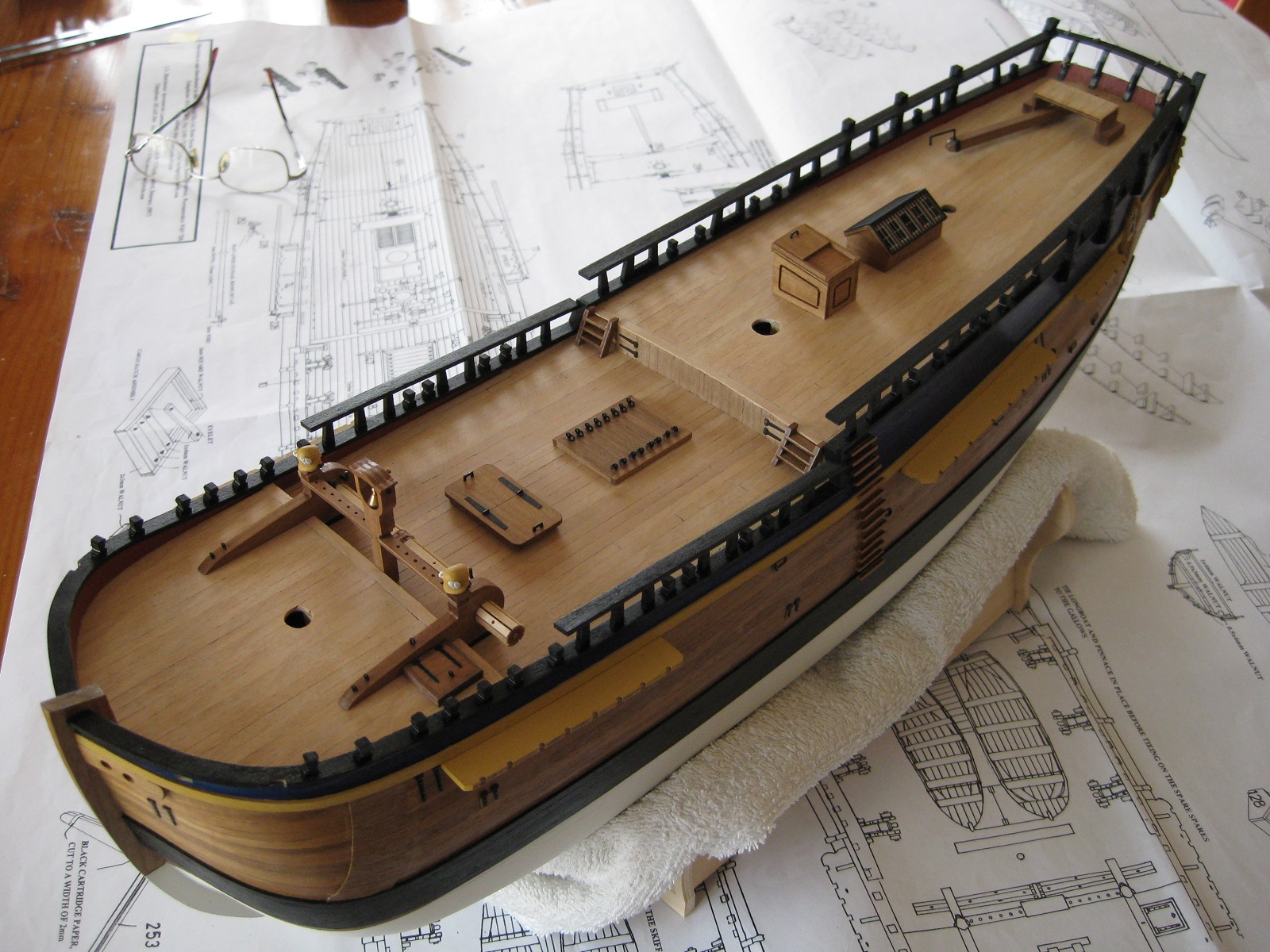
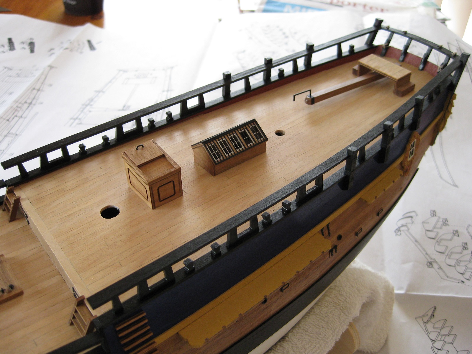
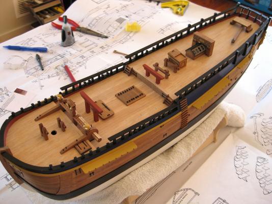
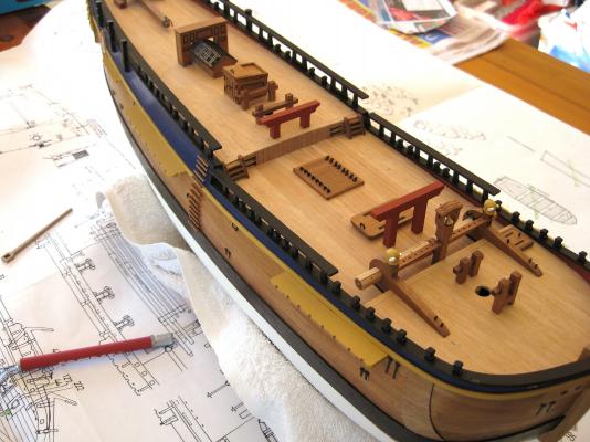
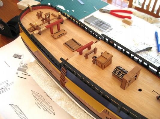
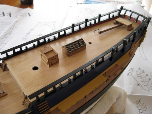
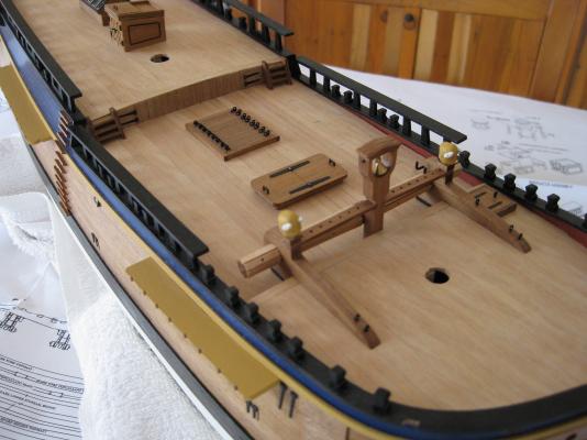
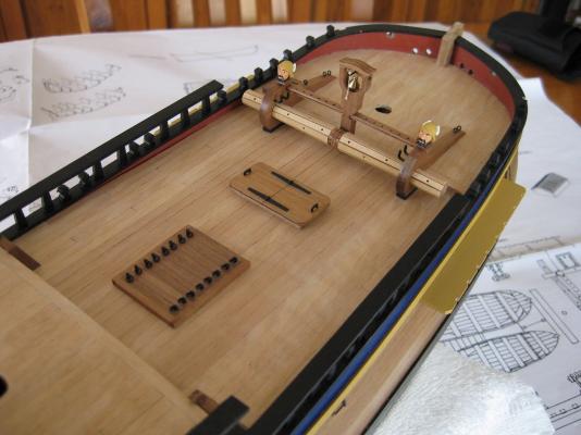
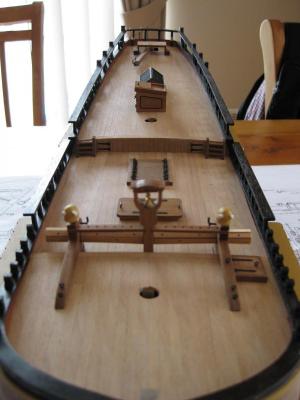
Hi, Deck furniture fitted. Next up will be the bitts and gallows. Cheers Slog
-
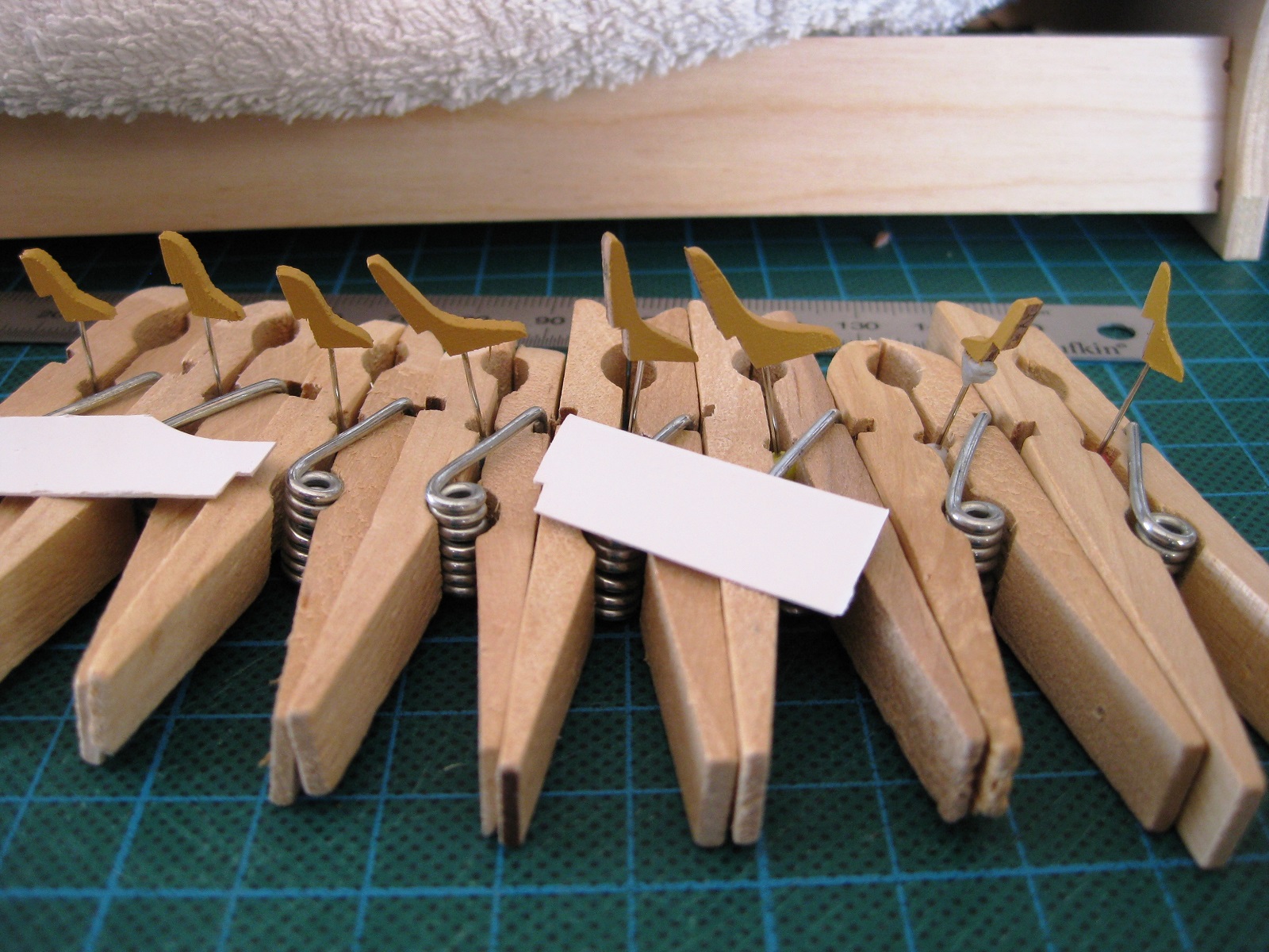
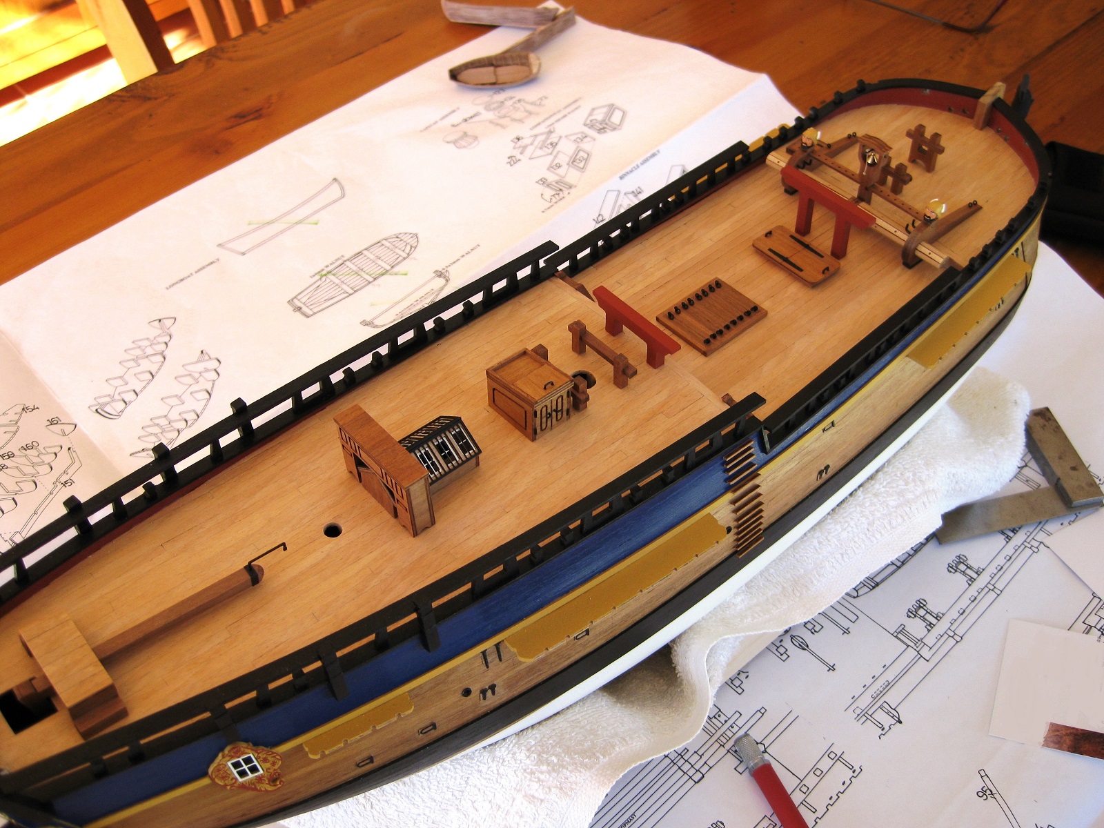
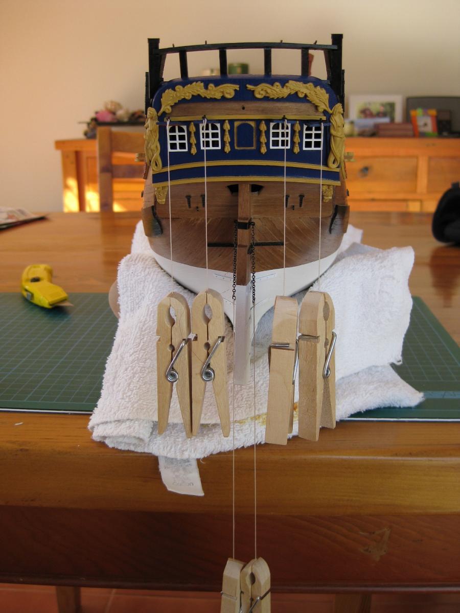
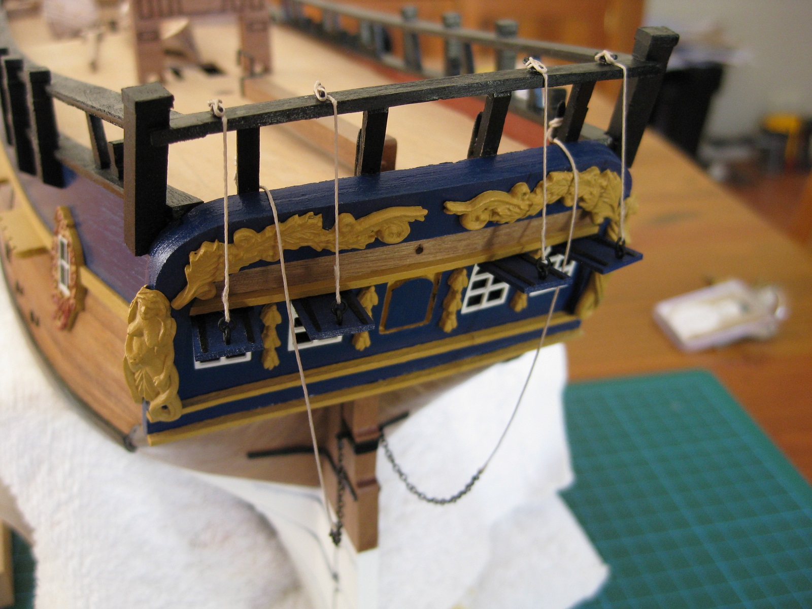
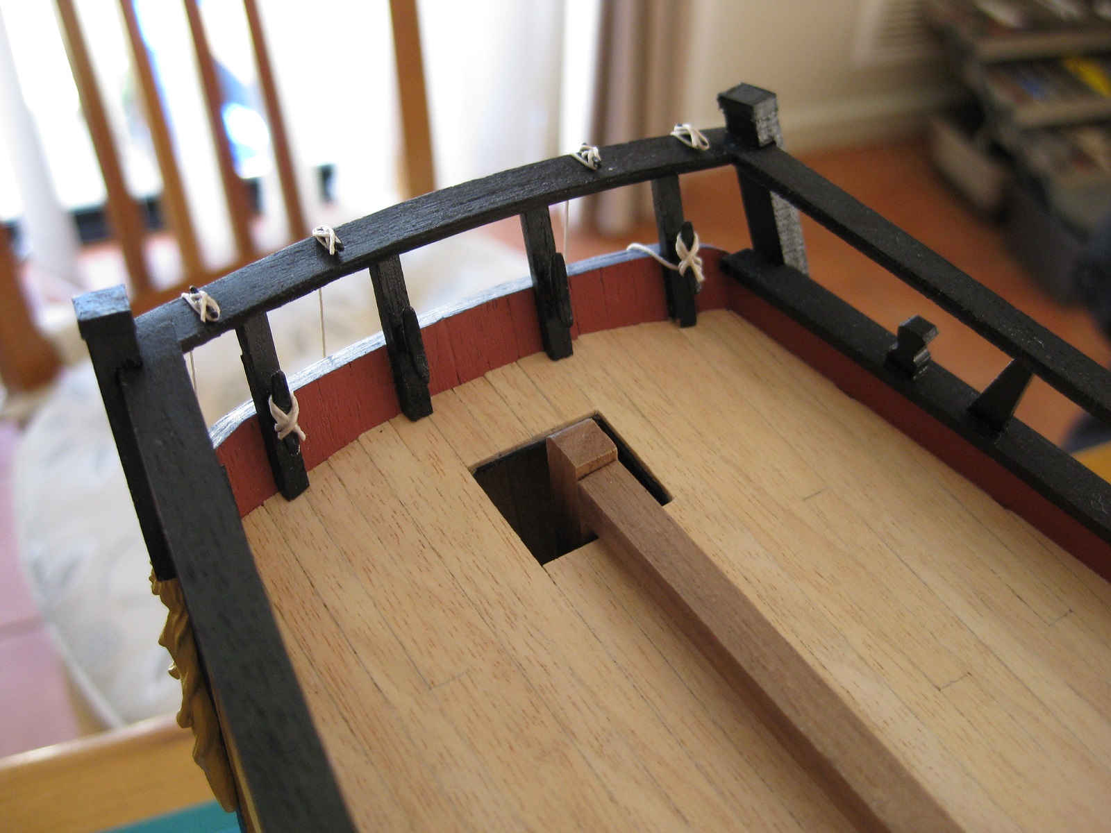
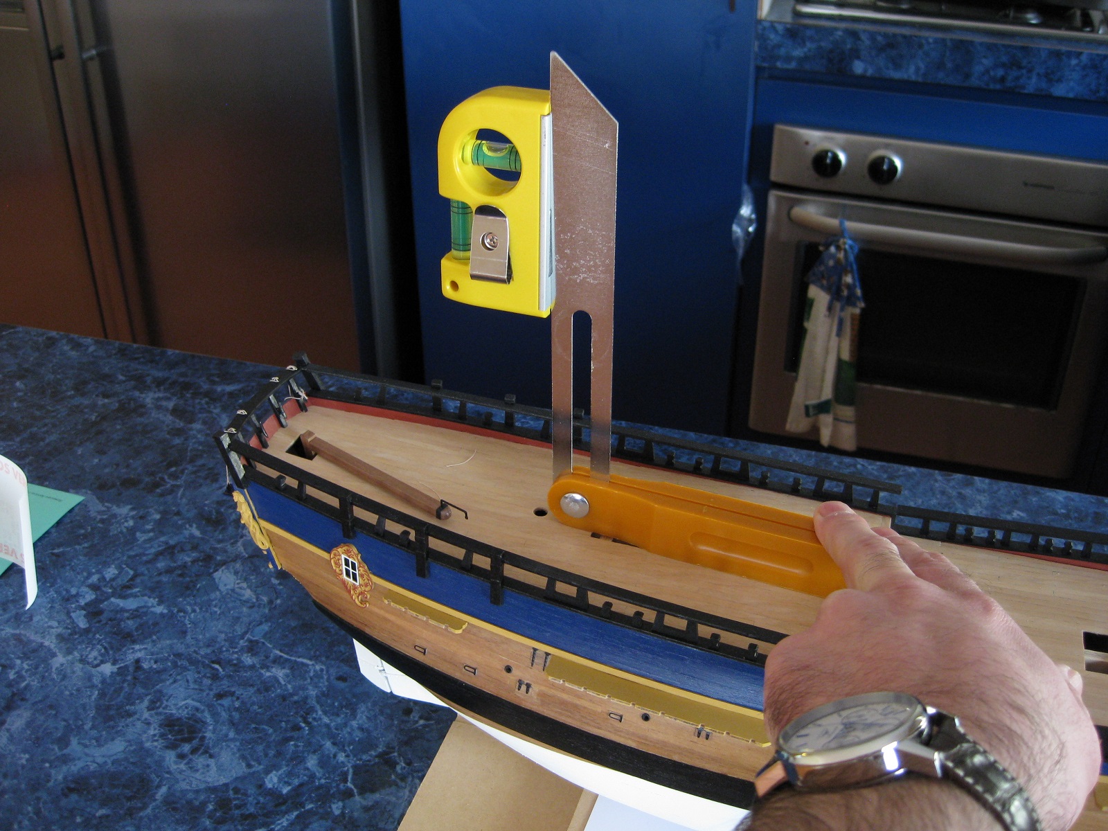
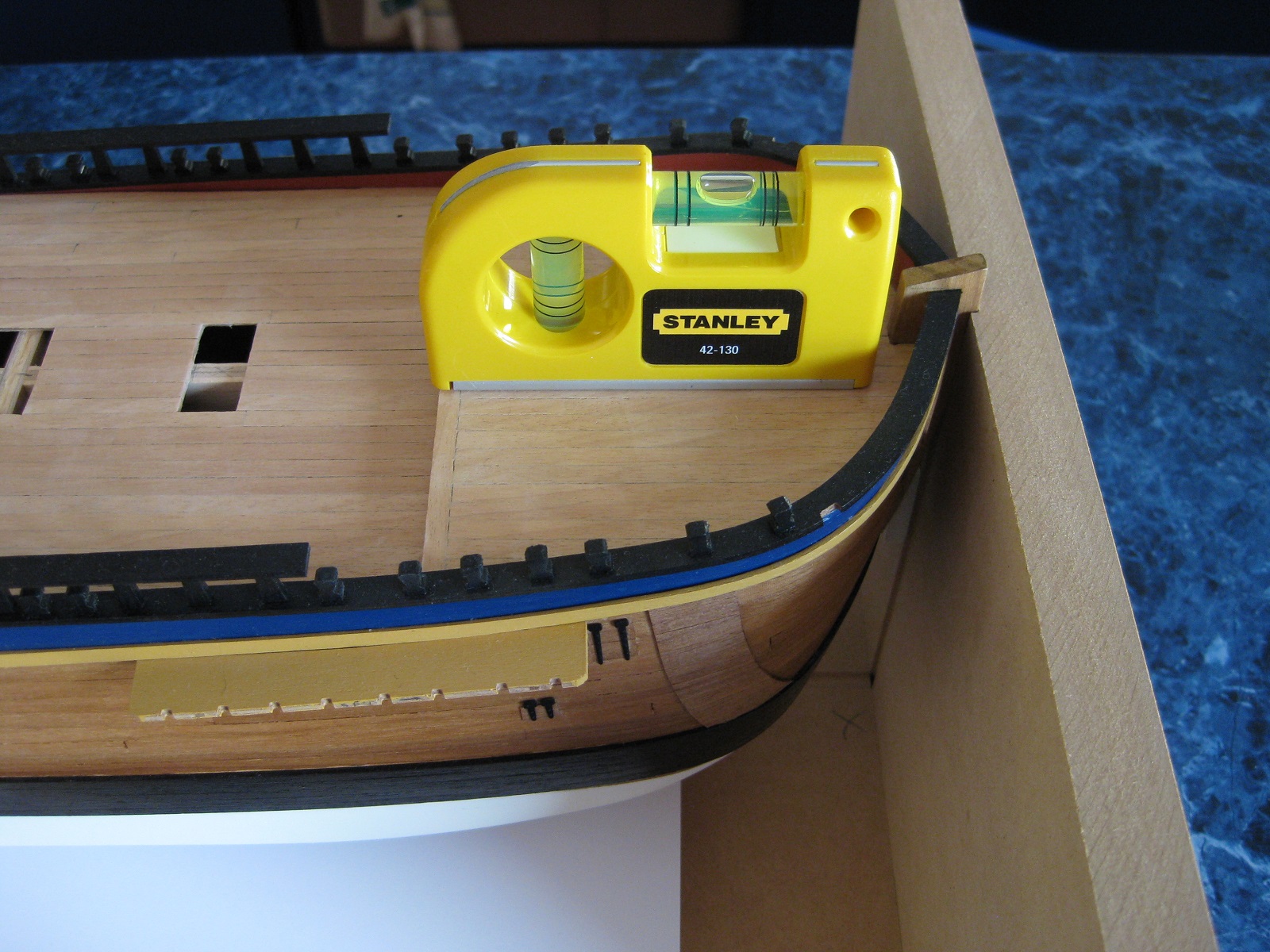
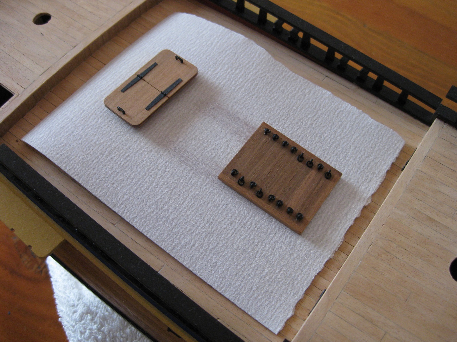
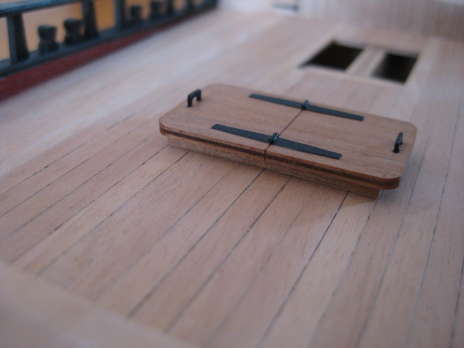
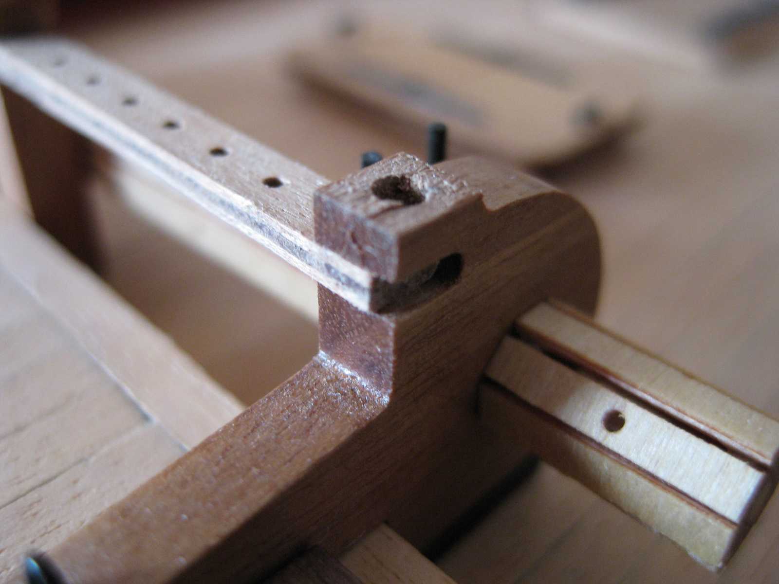
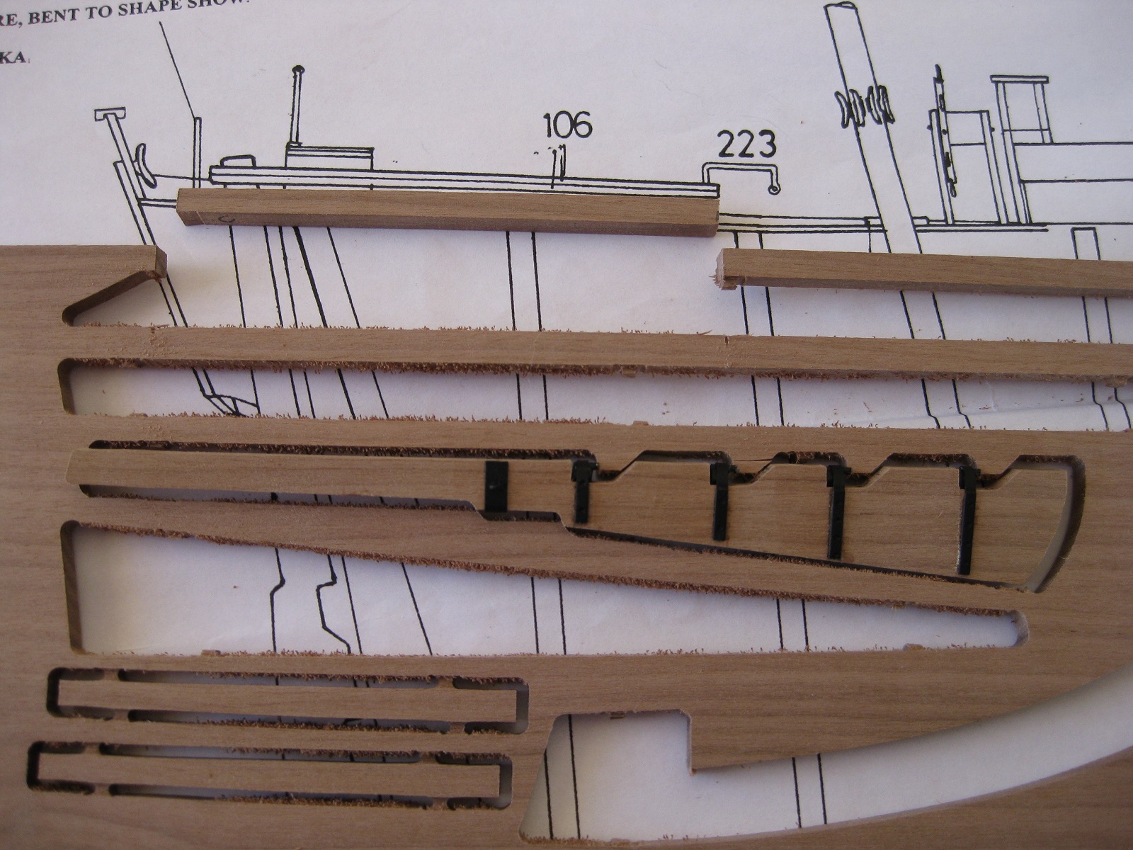
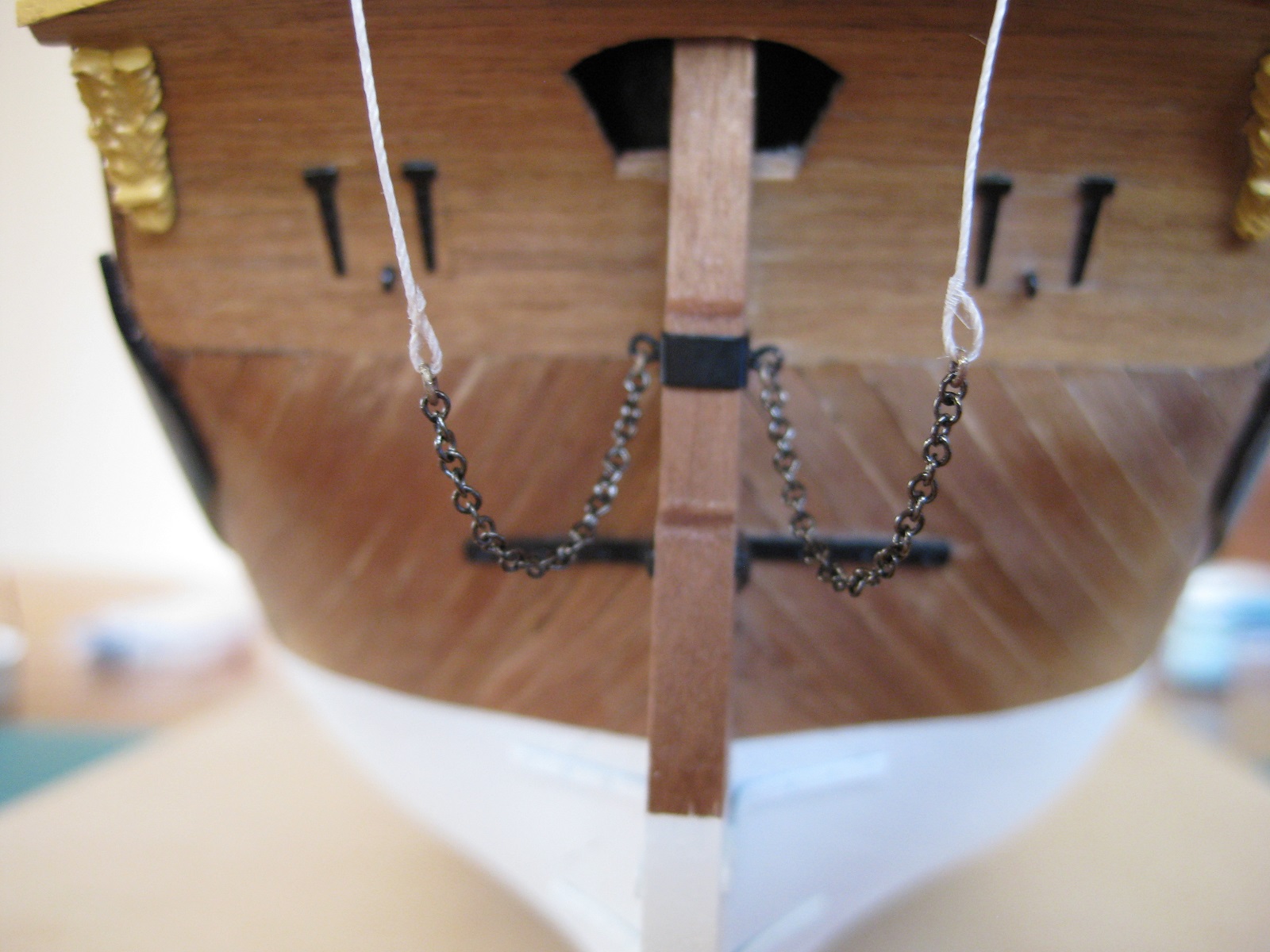
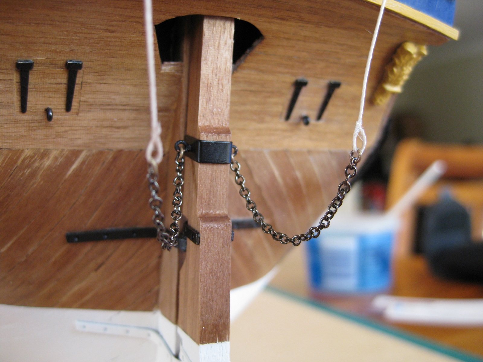
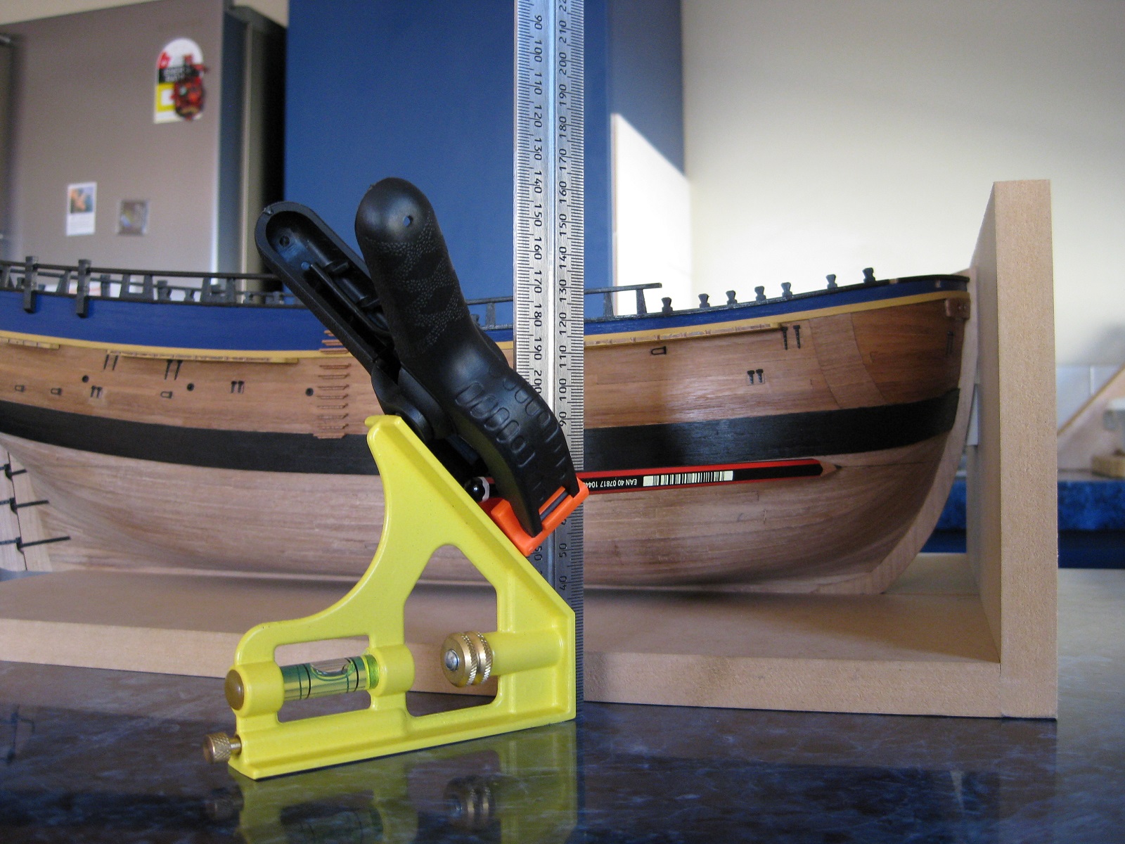
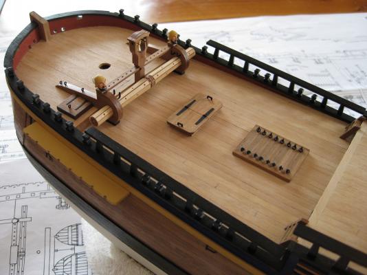
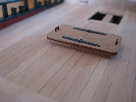
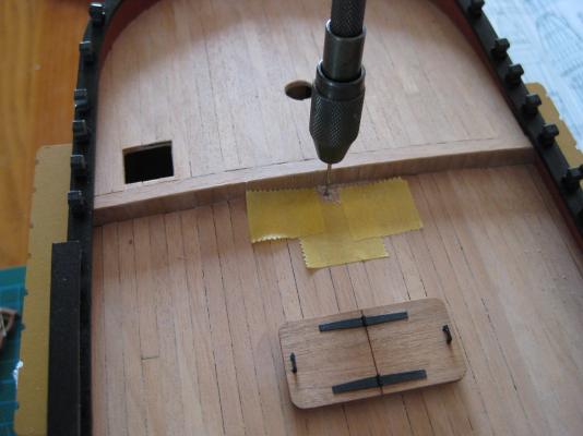
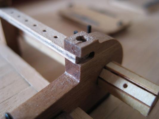
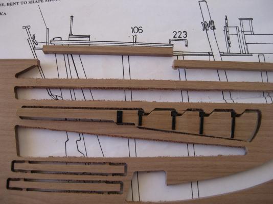
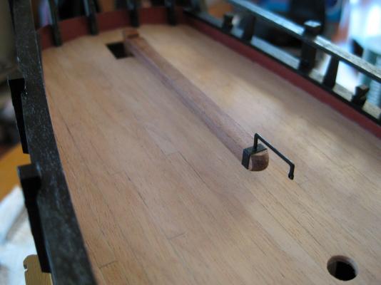
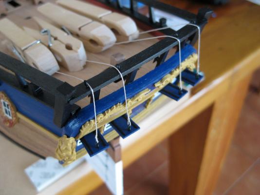
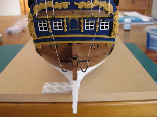
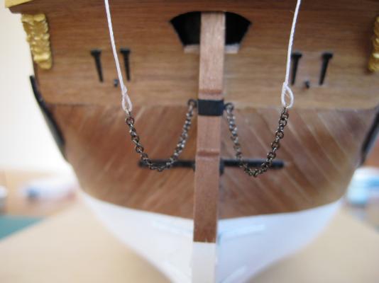
Hi All, A small bit of progress over the past week. As mentioned earlier the fake splices on the rudder pendants were annoying me so redid them. I also made up new chains and counted the links in each side to match, they were a couple of links different previously. Also the 0.25mm and 0.5mm rigging thread for the deadlights and pendants respectively weren’t sitting correctly, so I suspended clothes pegs off the ends of them and then brushed on a 50/50 mix of PVA and water and them pulled the excess off with my fingers. When they dried they were stiffer and straighter and could be manipulated easier. They now look more like they are pulled tight under tension due to the weight of lids and chains. I also removed the eyebolts from the taffrail(?) for the deadlight ropes and replaced them with some cleats made from 0.5mm brass wire bent to shape. They aren’t the best but get lost under the rigging thread anyway. I decided to fit what deck furniture I had made previously. I needed to find the angle of the rear deck as it slopes upwards to the stern so I can sand the correct angle on to the bottoms of the bitts and binnacle so they sit vertical when fitted. With the hull sitting level I used a sliding bevel placed on the deck and then a small level attached to get the blade vertical. Now I have the correct angle I will adjust the square on the disc sander and sand them to fit. I didn’t manage to get this done. With the hull level, the middle and fore decks are also level so can just use a small engineers when I get round to fitting the bitts and gallows in these areas. Started fitting the furniture with the 2 middle deck hatches. As these were made with straight bits of wood and the deck has a camber on it I placed some sand paper directly onto the deck and sanded the hatches back and forth to get the cambers correct. Second shot shows a decent fit of the hatch to the deck. Next up was the belfry. I marked the position on the deck and then drilled holes in the base of the belfry and the deck to take 1mm brass rod to secure the various bits and pieces to the deck. Will do the same with the bitts and gallows. Once the belfry and the windlass were glued in place I could fit the CNC cut belay rails which joins the belfry and windlass frames together. I don’t think I messed up as the windlass was constructed as per the plans and parts supplied but the belay rails were short. I don’t know if anyone but a Caldercraft Endeavour builder would know or care but I made new ones from the same ply sheet the originals came from and used the supplied ones as templates. Will post some pictures showing my furniture fitting to date shortly. Cheers Slog


-
Hi Jeff, Just catching up on your build and your rigging is looking first class, nice work.
-
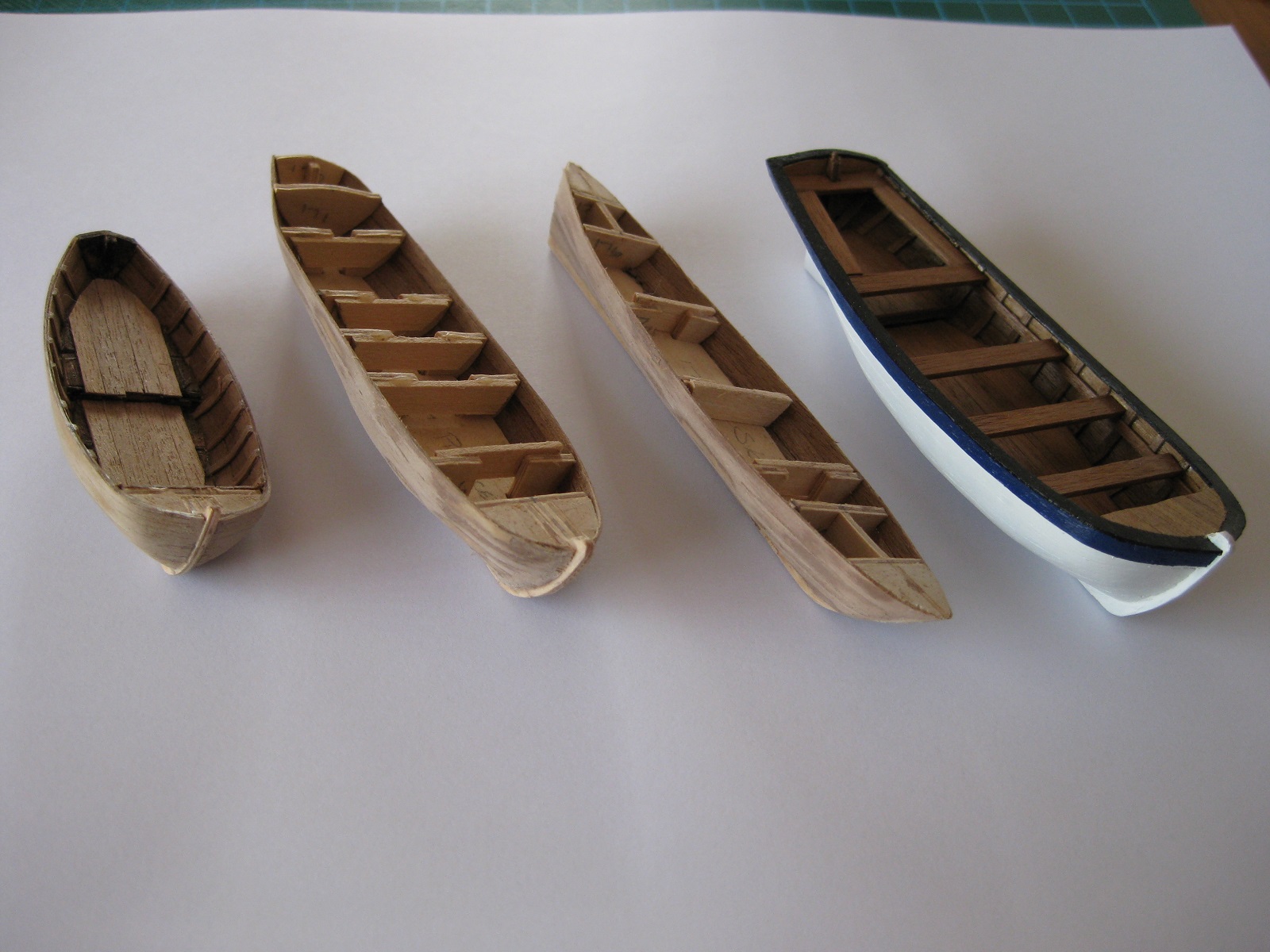
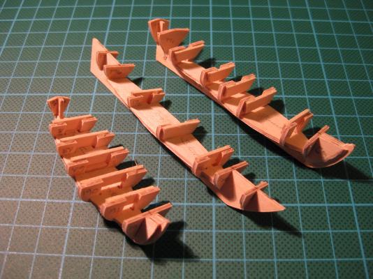
Hi All, Thank you all for your nice comments. Wayne, that was my 1st attempt at using the rigging thread and again the dreaded macro emphasises any discrepancies. I had a good look and the chains also had uneven amount of links so redid the chains and the rope splices again as it was really bugging me . Newmanrj, always good to see another Endeavour. I think it was Wayne who said earlier that aussie builders are drawn to do the Endeavour, how true. I suggest you start a build log of yours as there will be plenty of people looking over your shoulder to help out if needed. Shipcarpenter, your Santa Maria is looking very smart indeed and enjoyed seeing your metalwork. Look forward to seeing your Endeavour when you get round to it. Hi Nick, Caldercraft supply all 4 boats on a CNC machined sheet of 1.5mm plywood. I lost all my photos of that stage but found 1 with the skeletons glued together. I added scrap cross pieces across the ribs as I kept squeezing them together by mistake The photo below shows all 4 at various stages. From left to right: Yawl (70mm), Pinnace (99mm), Skiff(109mm) and the finished Long boat (98mm). I had a look on the Cornwall Model Boat site and they sell individual ships boats from Caldercraft and Amati but I couldn’t see the ply sheet ones like in the Endeavour kit but they may have something to suit. Alternatively maybe contact Jotika direct and see if they will sell the ply sheet by itself? A bit of progress. After redoing the rudder pendants I went on to the tiller. The supplied tiller is 2 parts from one of the ply sheets which is glued together and then fitted to the top of the rudder. It looks a bit chunky where it slips over the rudder and after gluing it up and almost fitting it on I decided to see if I could make a simpler, slimmer version. I got the walnut sheet where the rudder came from so the tiller was the same thickness and looked to see where I could steal it from. I choose the top section as it meant apart from cutting to length I didn’t need to shape it any I laid some scrap ply on the deck to get the height right and then shaped the end against the rudder and drilled a 1mm hole and glued in a piece of brass rod and then drilled a receiving hole in the rudder. Finished tiller. I glued and wrapped a 2mm wide strip of cartridge paper round the tiller to simulate an iron band and then painted and fitted the photo etch tiller handle. Cheers Slog


-
Hi Adrieke, I got the same paint set when I bought my Endeavour. Be careful with the Matt Varnish depending on the look you want. It does exactly as it says in the speil "does not change the appearance of the wood". I used it on my deck and expected the grain to become a bit more emphasied, but it didn't change the appearance in the slightest and even after 2 coats you couldn't tell the deck had been varnish. If that is the look you want then your laughing! Also don't use it on top of previously painted surfaces as it can leave a hard milky appearance. I used it on my red bulwarks thinking it would provide added protection to the paint but like I said it left a couple of milky areas. Cheers Slog
-
Hi Rowan, Welcome to the Endeavour club. I missed your log until now. You're off to a flying start and looking good. Slog
-
Hi Wayne, these latest photos show just how clean and crisp you build is, fantastic. The morter looks great.
-
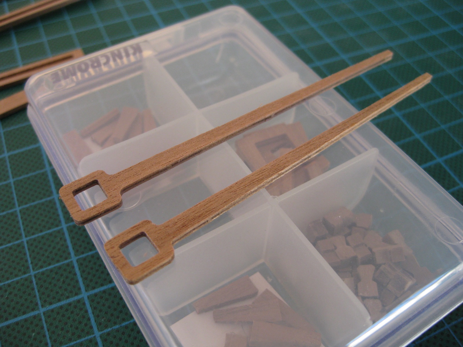
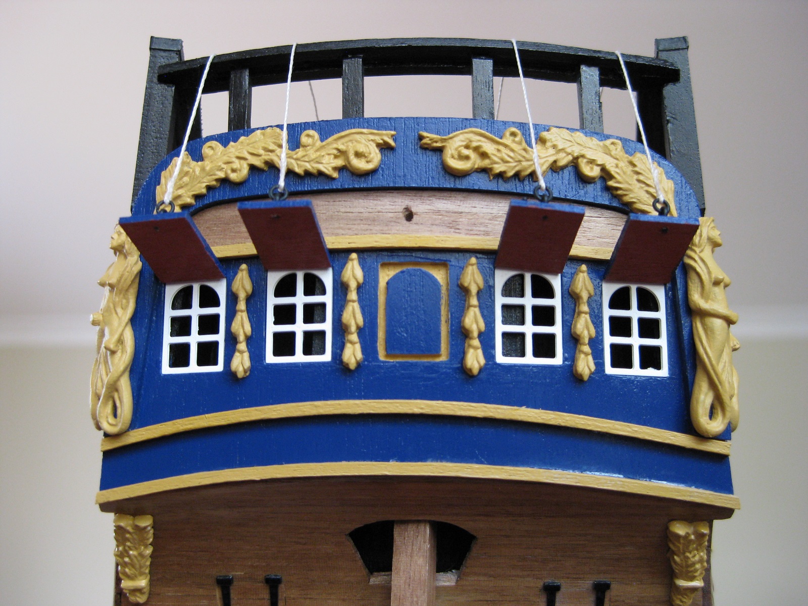
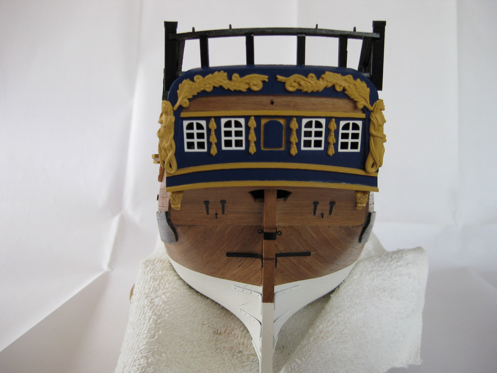
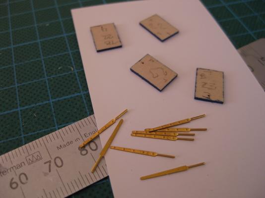
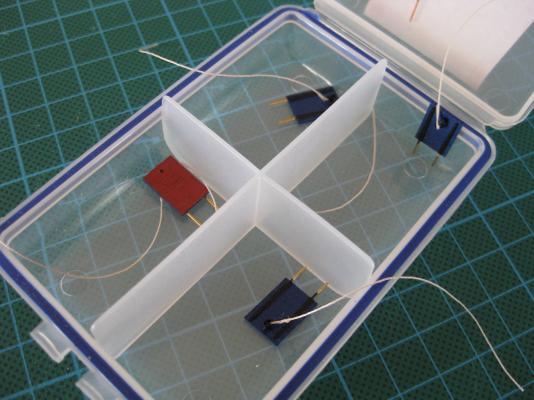
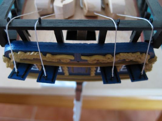
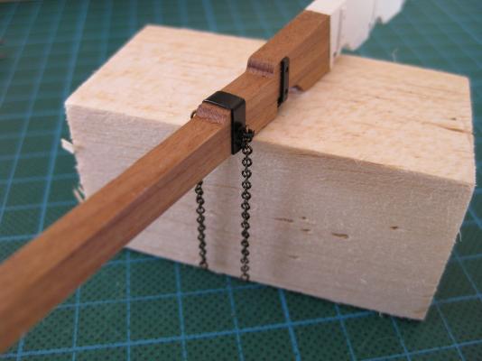
Hi All, Thanks Ron for dropping by and the comment. I used to have 3years of photos from box opening until now but unfortunately lost the first year and a half’s worth in a hdd failure. Only have from sanding second layer planking to now. I am going to work from the stern forwards now, doing both hull and deck details. 1st on the list is the stern window lids/covers/deadlights? The deadlights are from the 0.8mm ply sheet, parts 22 & 23. The 2 outer lids are different from the 2 inners due to the shape so needed to make sure I didn’t mix them up. Marked them with the numbers before cutting them free and then used a plastic storage box to keep them in the right order. The brass hinges have small tangs which go into drilled holes. The plans say to use 0.1mm rigging thread for the lanyards but I choose 0.25mm instead. I faked the splices by using a needle to pierce the thread and then pulled it through. I got that tip from Gil’s Victory log but mine don’t look half as good as his. I haven’t attached the ropes yet as I might make small cleats to replace the eyebolts as per the plans. The plans don’t mention attaching rudder pendants but the AOTS shows them with the lower section as chain and attached to eyebolts in the rudder and the upper section as rope which runs up past the deadlights and I will tie them off on the big stern cleats previously fitted. The chain I bought probably 1 ½ years ago from Modellers Shipyard but can’t remember the size (1mm?) I had no idea what size of rigging thread to use so settled on 0.5 which seemed chunky enough to hold on to an unshipped rudder in real life. I was quite chuffed with the effort, using the same cheating splice, until I saw the photos . One of the splices is average and the other is terrible so I will do them again. I think I will try and get some bees wax also as the 0.5 line isn’t hanging as I would like. Cheers Slog


-
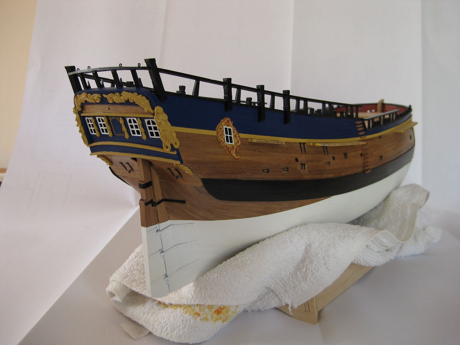
Hi Wayne, Thanks for the comments. The paint I use is Jotika/Caldercrafts own Admiralty Paints, yellow ochre. I ordered the white hull paint set from Cornwall Model Boats when I purchased my Endeavour from them. There is an Aussie stockist of Admiralty paint at the following website http://www.miniaturesteammodels.com/category89_1.htm I have found the Admiralty Paints to be very good especially for coverage particularly the red ochre, black and French blue. I have been having difficulties in airbrushing with them but can’t be sure if that is just acrylics in general or my n00bness. Cheers Slog
-
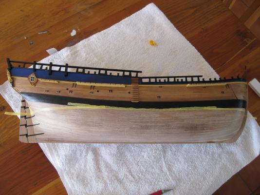
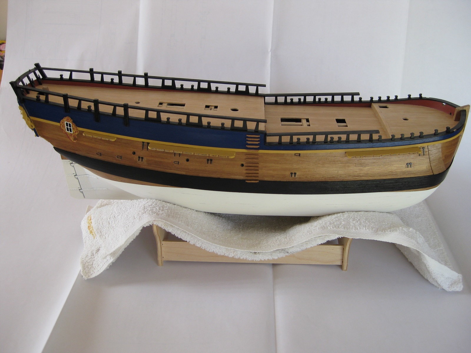
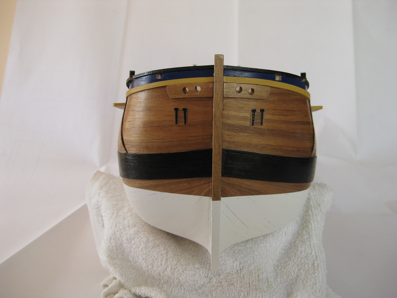
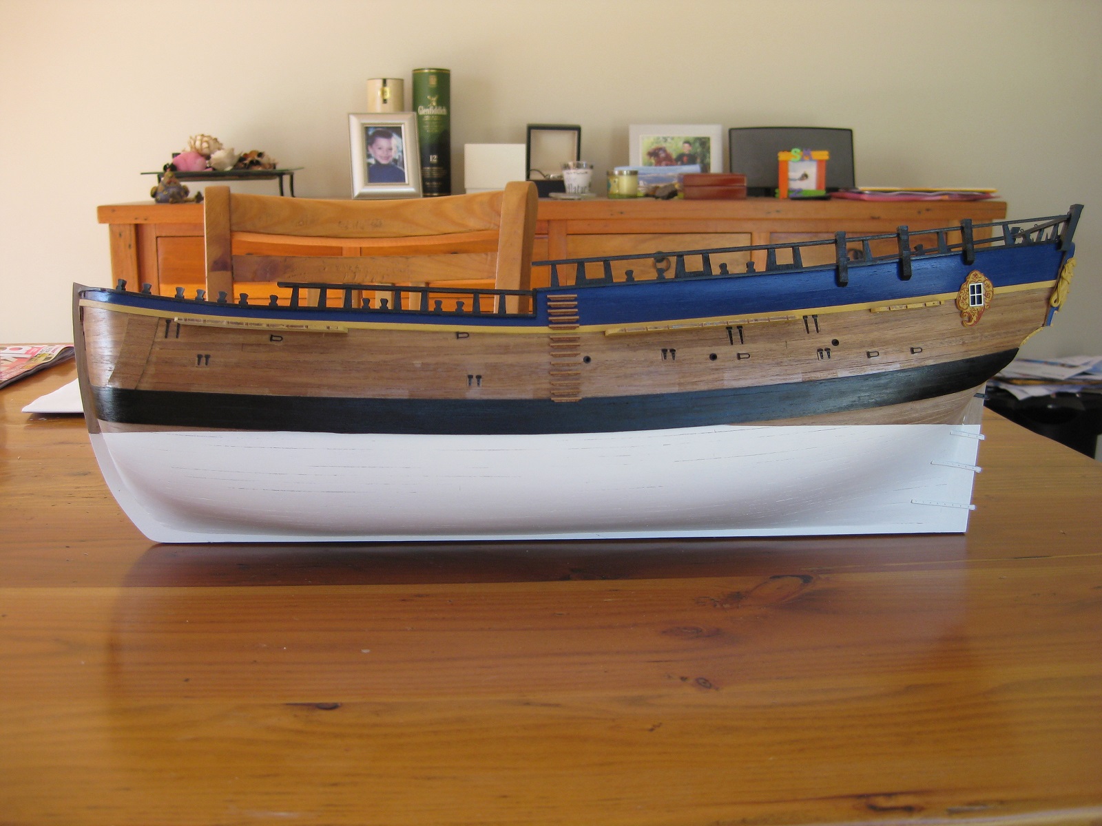
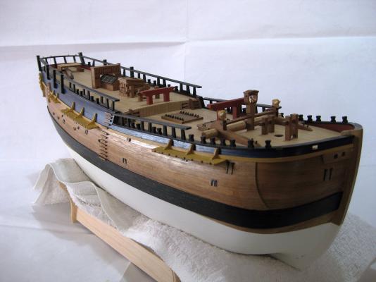
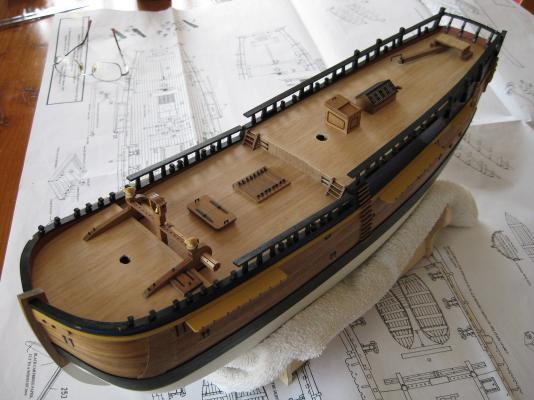
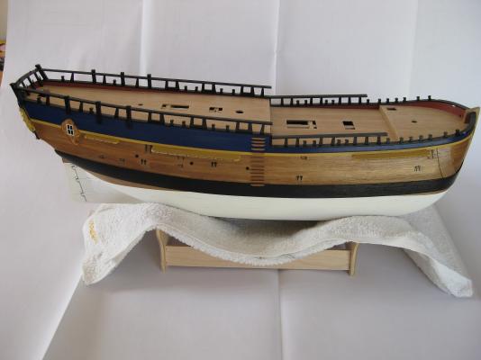
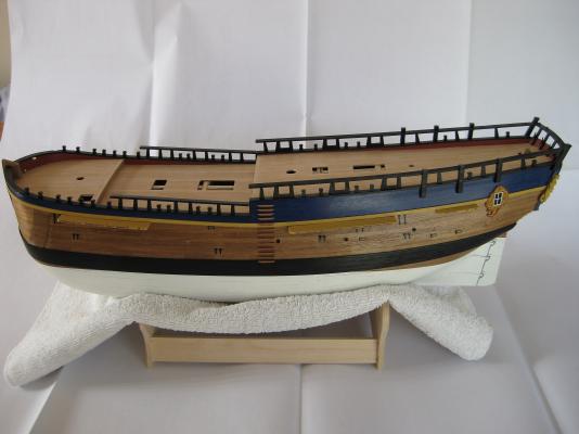
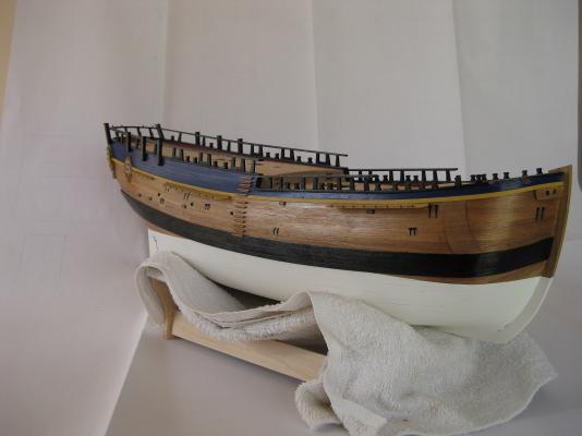
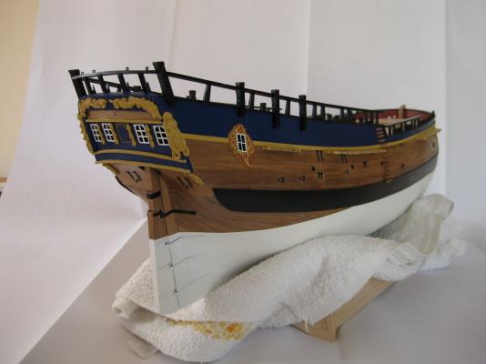
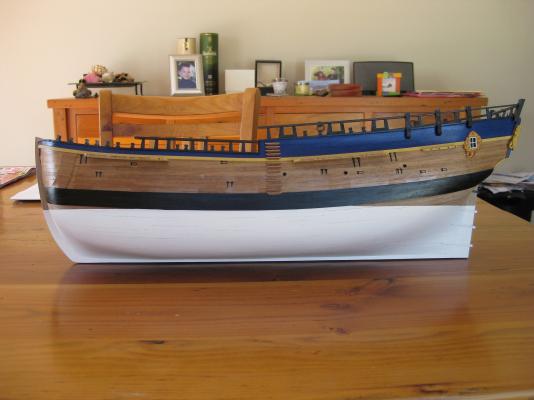
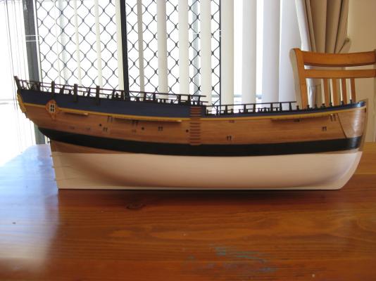
Hi All, Well a major milestone, 3 years in the making has been reached. The hull is essentially finished. There is still a lot to do to it but its all little detail work and of course the deck furniture. A lot of blood, sweat and tears to get to this stage but overall relatively happy with the outcome. There are a lot of mistakes made along the way and lots of lessons learned. Cheers Slog


-
Hi Greg, looking real nice
-
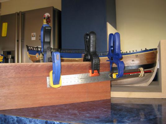
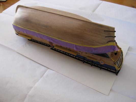
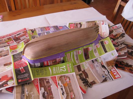
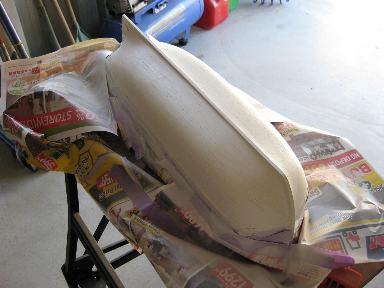
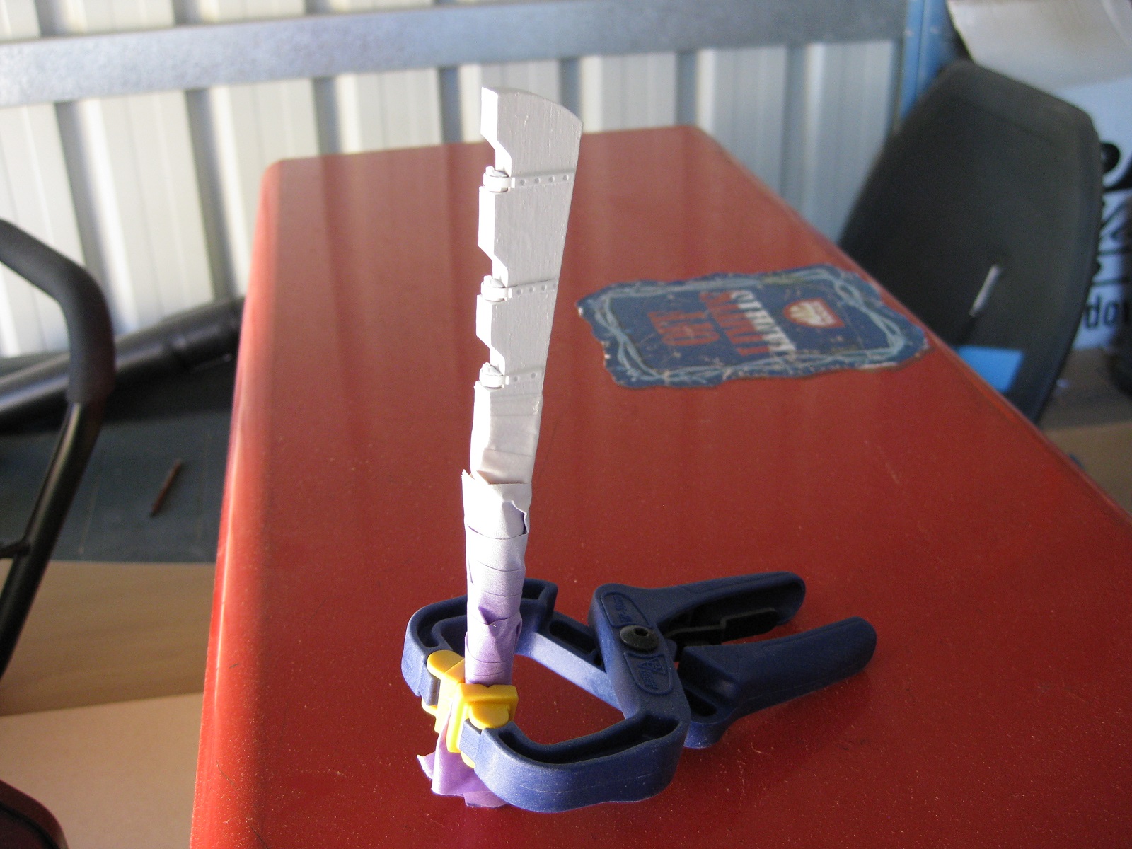
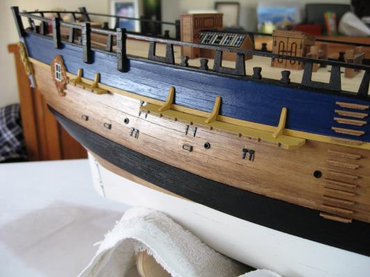
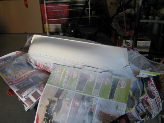
Okay, here’s part 2 of the sorry tale of hull painting. After masking up the hull in the last post I set up the airbrush and mixed up the Admiralty Paints Hull White. In previous posts with experimenting with the airbrush I tried using Tamiya Acrylic thinners which didn’t really work very well. This time I just used water and it was a lot better. I decanted about 10ml of paint and mixed in 3ml of water and the consistency looked very good. I then started spraying one side of the hull first going round the stem, keel, stern post and the water line and then filling in the hull. The first coat was very light and could still see the walnut underneath. It would take a lot of light coats to cover the hull fully. I did a couple of coats like this and again they were very light to build up the opacity. Then went to the other side to do the same and then that’s when it started to block the needle with build-up. I pulled the mixing cap off and cleaned it and continued spraying but the paint flow quickly reduced again and after getting a couple of light coats on the other side I gave up in frustration. I took the ship outside and sprayed it using the Citadel Skull White from a spray can. Got a bit wet at times but it’s very forgiving as each coat flashed off it tightened up. But had some problems with overspray as will be seen in the photos below which I think was because of the large spray of the can and moving the ship which probably dislodged some of the masking paper. The airbrush had a small controllable pattern which wasn’t an issue. I would spray a lightish coat with the spray can come back in then go out and do another coat etc for several coats. This was a near disaster as I went back out and picked up the can gave it another long shake and started spraying only to see Chao Black going on to the hull! (I picked up the wrong can as they are identical other than the Paint name. Luckily not too much went on and a few light coats of the white covered it up. Here’s the rudder and hull painted in the shed. Once I peeled off the tape the actual waterline isn’t too bad. A lot better than expected with little or no bleeding under the tape. A bit of over spray in the corners where it was difficult to get the tape into the sharp internal edges. Looks a bit off going into the wales the way it does but I still think this was the best option. Here’s the horrors now. So much overspray got in under the paper I couldn’t believe it when I peeled back the tape. My heart sank. The starboard side copped it with the stern, some of the wale and the rough tree rails, stanchions and channels getting a dusting of white. If I persevered with the airbrush I wouldn’t have all the remedial work ahead of me, as usual will know better next time. I have already started to clean up the overspray with wire wool and fine grit paper. I have touched up the yellow channels and the stern castings and touched up little bits of the French blue. Also I covered all bare wood with a couple of coats of Wipe-on poly leaving only the black wales and the railings etc to re-do. Should hopefully get it finished up today which I will post pictures of the completed hull later. Cheers Slog


-
Hi Timmo, Build is coming along nicely. Your cannons look fantastic. I will start on mine soon, hope they look half as good as yours. By the way, I prefer option 2. Cheers Slog
-
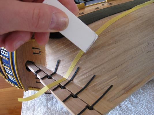
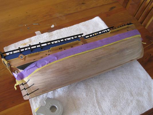
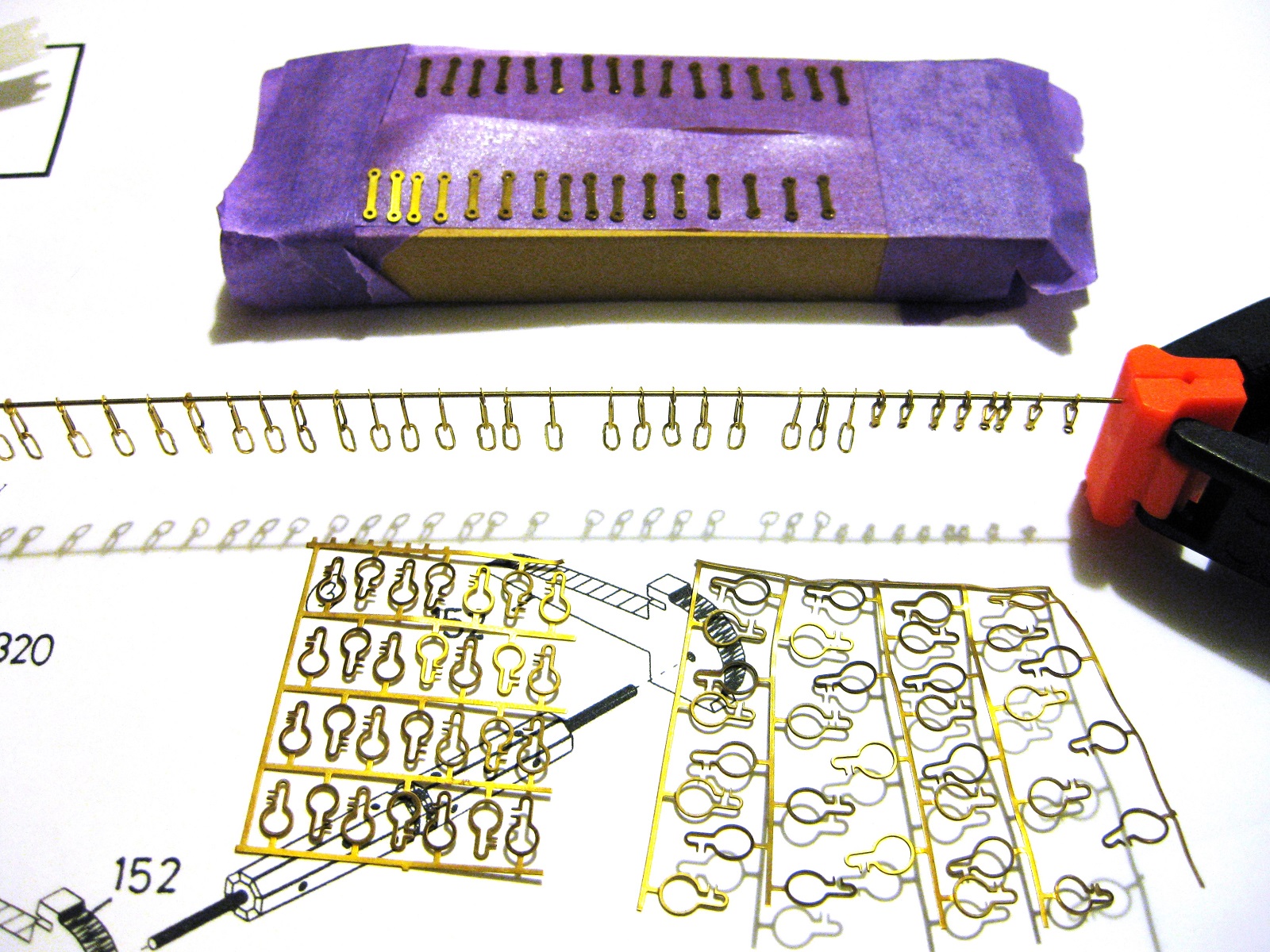
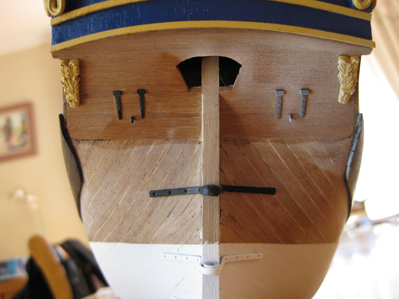
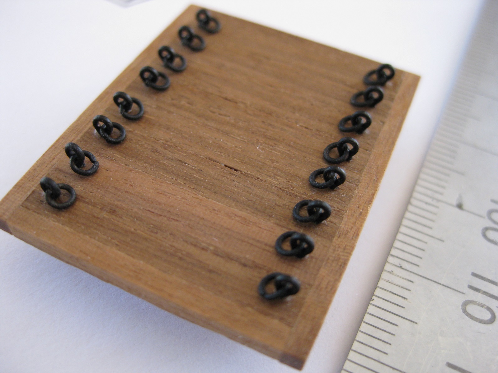
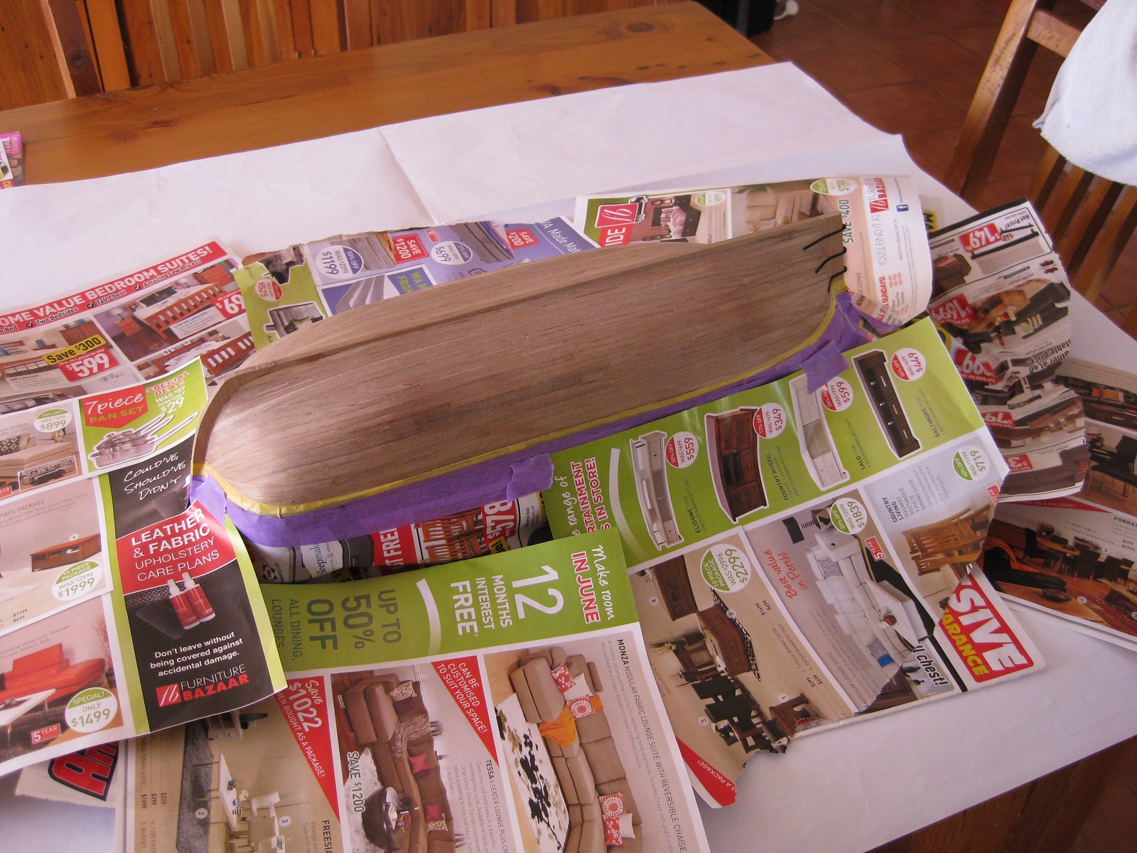
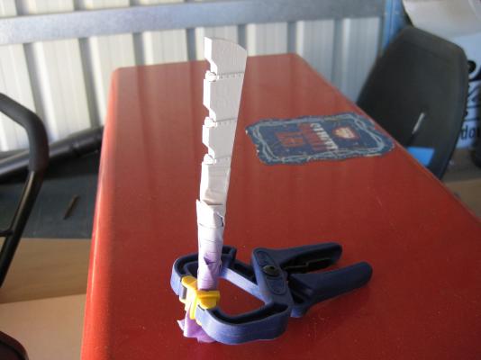
Hi All, A bit of an update on making eyebolt rings. I tried a couple of things to see if they could be made easier. Firstly, using the same technique of annealing the wire over the gas stove, I wrapped the same 0.5mm wire round a 1.37mm drill shank instead of the 1.12mm drill used the first time. This gives a real life hole of almost 88mm and an overall outside diameter of 152mm which is probably a fair bit over scale). After pulling the coil off the drill I re-annealed the coil to red hot again. The slightly larger ring allowed the point of the Stanley knife to get in further and I could cut 2 rings each time and was a lot easier as the brass was softer and didn’t lose the point of the blade this time. The larger ring also made it easier to grip with tweezers to feed through the eyebolt. Also the second annealing after coiling made flattening the ring and closing the ends so much easier and I think the ends closed tighter as the ‘spring’ of the wire had gone. I will continue to use the larger drill as although over scale the easier and far quicker fabrication is preferable to me. Now that I can make fairly reasonable eyebolt rings I decided to go back and re-do the mid-deck hatch. I originally made this as per the plans which instructed to use the supplied eyebolts as is and just bend then down flat to replicate the ring. These were originally glued in place with CA glue and the tail on the underside bent flat and more CA applied liberally along the underside. The bent tails were easily pried up with a finger nail and the eyebolt pushed back out through the drilled hole. After painting the modified eyebolts I glued them back into the drilled holes, which in my opinion looks heaps better than the bent over eyes. Time to paint the lower hull. I planned in using the following for marking the hull line. A combination square with a pencil clamped to it. 2 problems the pencil couldn’t go back because it hit the 45 degree angle part which meant it was pretty floppy out at the point and secondly because I used the hull holding jig I couldn’t get the point in close enough to touch the stem. I cam up with the following a bit Heath Robinson but go the job done and I could reach right in to the stem. If anyone has been following my log from MSW 1.0 you might remember that I placed the wales one plank width to low. This meant the water line didn’t match up with the plan and worse, it bisected through one of the rudder hinges. 3 options, place it where it is supposed to go and have a part white and part black hinge. Place it below the hinge but have a shallow waterline or place it above the hinge and have a decent white hull but the waterline intersecting with the wale. I placed the waterline above the hinge as in my opinion is the best option of the 3. I only had 18mm Tamiya masking tape which is too wide to follow the curve under the rear counter so pulled out a length and cut the 2 edges from to use. Looks a bit ragged on the top side which doesn’t matter as used the clean edge for the line. I placed the tape slightly above the pencil line and then used a eraser to buff the tape down and remove the pencil line After using the Tamiya tape to mark the line I used cheapo decorators tape to build up a bit of width ready for masking out with paper Again using the decorators tape I used a shiny newspaper supplement to cover everything else up. I think newspaper is to thin and there is the right the newprint will come off or bleed through if it gets damp. Here it is already for painting. I made this post whilst waiting for the white to dry. The whole painting process wasn’t too successful in my opinion as a number of problems crept up. I almost had a disaster which was narrowly avoided. I will go through the problems I had in my next post either later today or tomorrow once the tape is removed and the finished result seen. Cheers Slog