
Captain Slog
-
Posts
904 -
Joined
Content Type
Profiles
Forums
Gallery
Events
Everything posted by Captain Slog
-
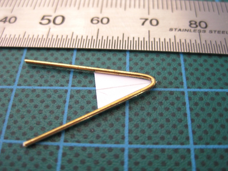
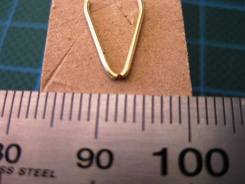
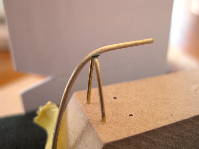
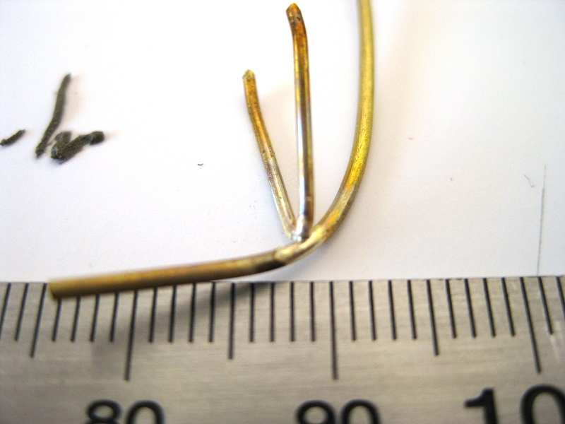
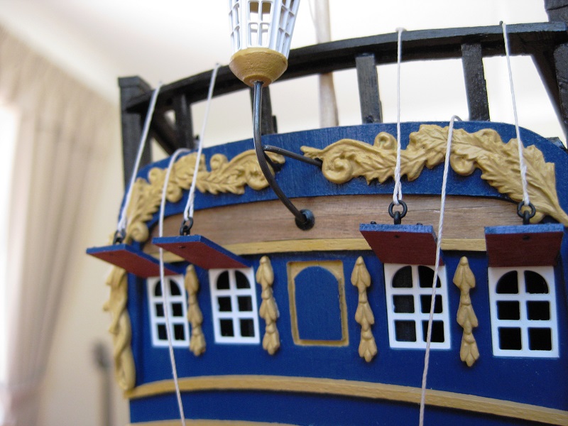
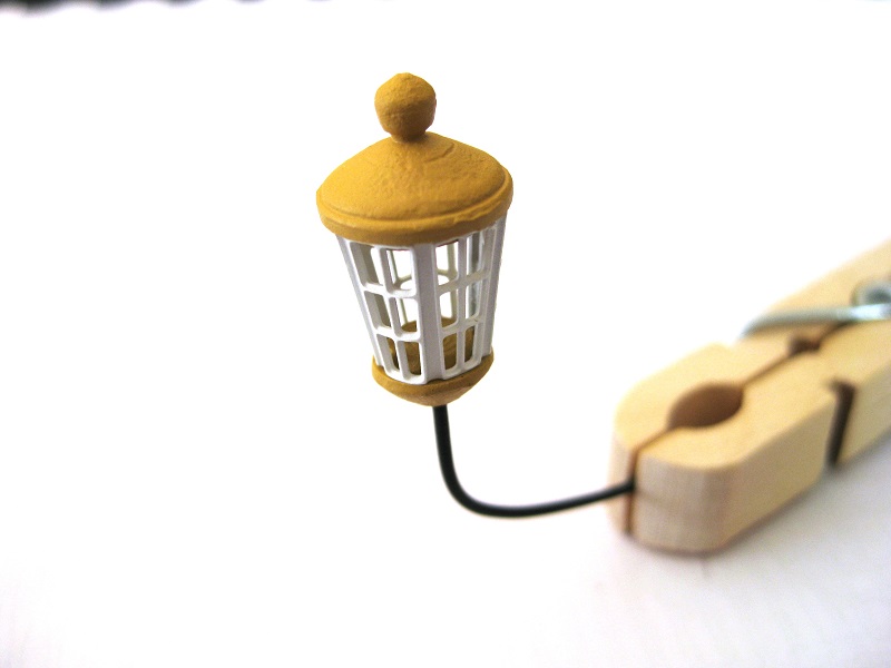
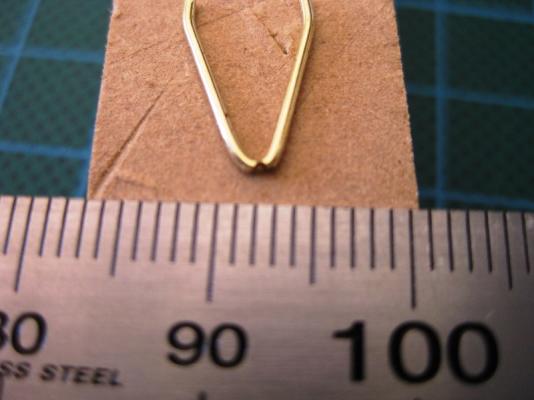
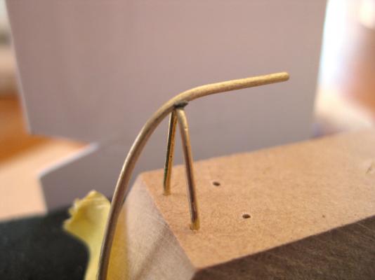
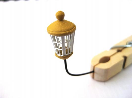
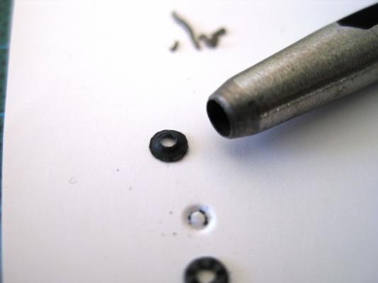
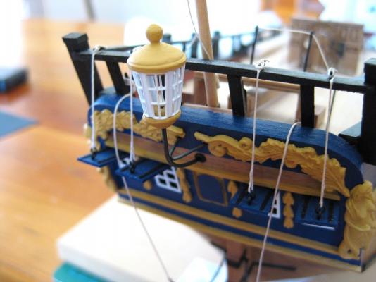
 Hi guys, Thanks for all the encouraging comments. Looking forward to seeing another Endeavour build Ross. As anyone who stops by my log knows I tend to jump around a bit and this post is no different (keeps me interested and stops me getting bored). Since I needed to get back and do some work as I have been pretty slack lately, but not in the mood for wood working, I headed back to the stern to work on the ships lantern again. I had previously finished the lantern and was pretty happy with it but it is very top heavy and teeters on the end of a 1mm brass rod support, which due to me drilling the hole in the stern a bit oversize it was going to be vulnerable to the slightest knock. From looking through the AOTS I knew it had side supports which triangulates the whole lantern making it very secure so decided to try this, plus it meant doing some more soldering which I enjoy. After deciding the position of the support legs and temporary placing the lantern in the stern I took some measurements and then cut out a small 11mm x 8mm card template to bend the support legs to. After bending to the triangular shape and bending the ends straight for fitting into the stern holes I filed a small groove in the point to accept the 1mm vertical upright. I did want to make the side support legs from 0.7mm rod so there was a noticeable difference in the diameters but only had 0.8mm which doesn’t have the same effect. To solder together I drilled a couple of holes in some MDF and stuck the legs into and then taped the vertical support in place. I applied some silver solder paste with a needle to the join which can just be seen in the photo, but in retrospect I could have used a bit more. Soldered joint complete and after trial fitting and tweeking the fit I dropped it in to hydrochloric acid for a soak and then into the blackening solution. Whilst the support was blackening I decided to make a sort of escutcheon plate to tidy up the area where the stand enters the stern and to hide my slightly oversize hole. I used the black cartridge paper (this stuff is great and have used it throughout the build) and using a 3mm and 1mm hollow punch made the escutcheon plate. I just had to remember to slip it on the support BEFORE gluing the lantern to the hull. After a final trial fit I glued the lantern in place and then the whole assembly to the three holes drilled in the stern. I slipped the escutcheon plate down to the hull and used wip-on poly applied with a little paint brush to fix the plate in place and job done. Cheers Slog
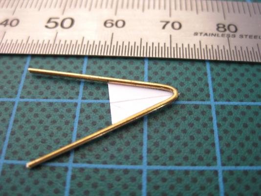


-
Hi Kevin, I am pretty sure most of us have felt this way at some time or another, I know I have. There is aspects of my build that I am never happy with and know that its unlikely to be better but then there is other parts I know I can do better next time and the time after that. But if we give up then the practice will never be there to improve. For what its worth I am enjoying your build and see nothing but good work. Keep it up mate. Cheers Slog
-
Hi Dick, Following along for the ride and impressed with you ship. I was curious to Brians comment about the name. I can't believe they would called Christen a ship Big Belly so had a look in Google Translator from French to English. Gros Ventre - Potbelly Gros Venture - Big Venture (more believable for an exploration ship) I wonder if there is a typo somewhere and Venture is the same in French as well as English? anyway, enough rambling nice work Dick. Cheers Slog
-
Hi Jeff, Looking good. I can't help with the cutting but read somewhere on the site where someone stuck, I think, masking tape to the underside of the rule which might be enough to grip the plate when applying downward pressure on the rule. I have never cut plates but when I cut photo etch I never do it on the cutting mat as I found the mat has enough give to bend the photo etch before it cut through, distorting the photo etch. I always do it on a scrap piece of MDF but like I said never cut coppering plates before. Cheers Slog
-
Well that was short lived Right class, Canopus, but not the Albion, no point making you guess the other 5. HMS Ocean. Chosen because it was mentioned in 'Dreadnought' I am reading. See you all in another 150 pages Your turn Jan. Slog
-
making chisels
Captain Slog replied to michael mott's topic in Modeling tools and Workshop Equipment
Hi Michael, Thanks for the fantastic information, most helpful Cheers Slog -
Wow, I finally got one right, after 151 pages LOL I don't usually play but follow the thread as I like seeing all the different pictures of ships. Don't know how easy this will be so no clues just yet.

-
making chisels
Captain Slog replied to michael mott's topic in Modeling tools and Workshop Equipment
Hi Michael, Very neat. Would you mind detailing the hardening process you employed. I vaguely know about heating up, quenching, heating again and air cooling or vice versa. Cheers Slog -
Hi Menno, Is it...wait for drum roll...Gwalia? Cheers Slog
-
Hi, Is it Glen Gower? Cheers Slog
-
Hi Mike, Nice work on your carriages. Mine have ground to halt again. With regard to the wheels, I think I read somewhere on the site that the wheels (trucks) wouldn't have steel bands round them as they would chew up the deck, but maybe someone more knowledgeable than me can give a definitive answer. Although saying that it is your ship and the bands do add some detail. Cheers Slog Just on the blackening, I soak my brass in Hydrochloric acid and been quite successful up until now with blackening the Caldercraft brass barrels.
-
Hi Greg, Your rigging looks incredible. very neat. Cheers Slog
-
Hi, This looks like it will be an interesting build and look forward to following it... ...but stupid question time. What are the 6 'poles' hanging down the side of the hull? I only recently learned that similar poles on dreadnoughts etc were for torpedo nets...surely a ferry wouldn't have these Cheers Slog
-
Hi Jeff, thats a bit of an understatement! I would say that it turned out excellent! Must remember to try the tape technique when I next do the dreaded planking. Cheers Slog
-
Hi Jeff, Your planking looks very tight indeed, nice. I am a fan of painting hulls like the original but this would look good left varnished! Cheers Slog
-
Hi Steve, Very inventive I find this area of the masts with the relationship between the cheeks and hounds very confusing so will be watching with interest. cheers Slog
-
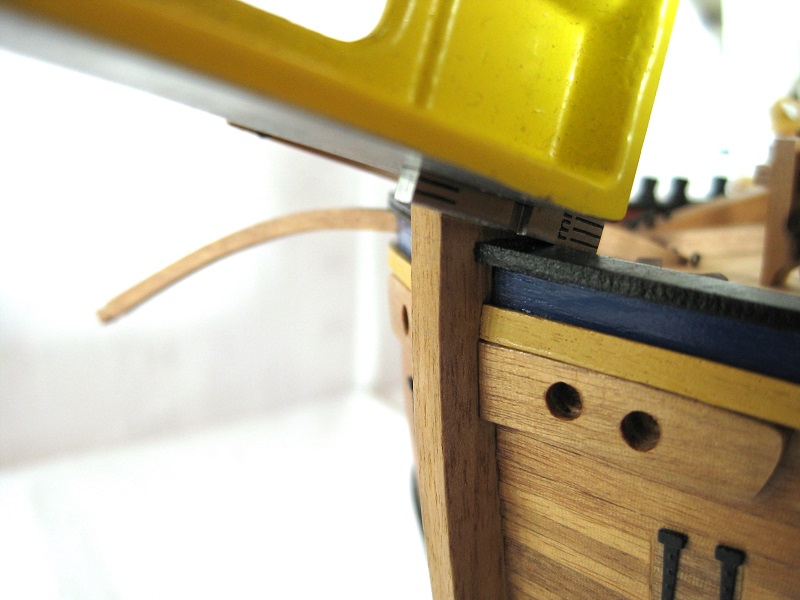
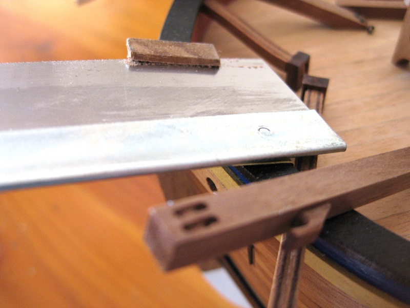
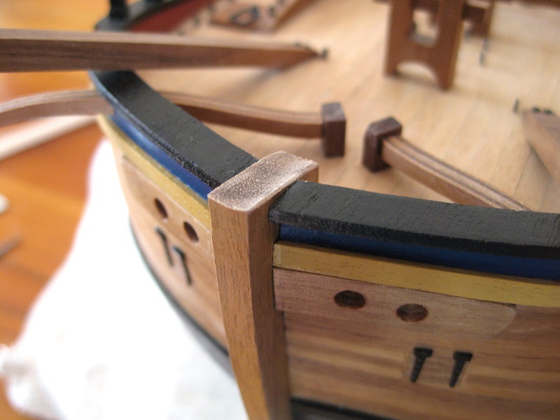
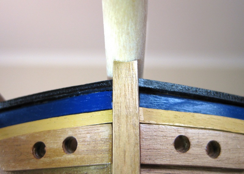
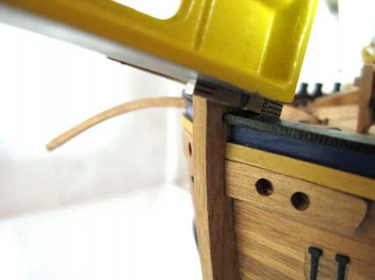
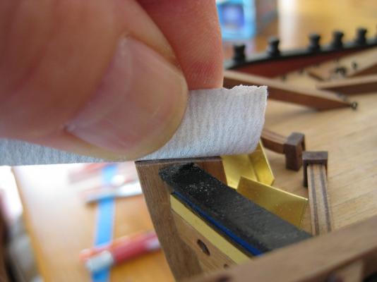
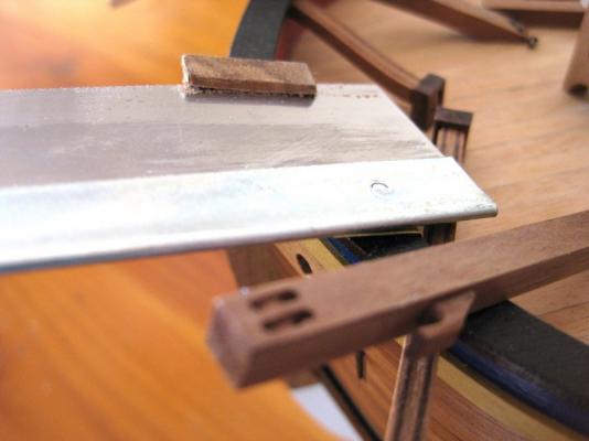
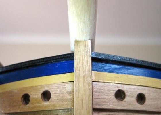
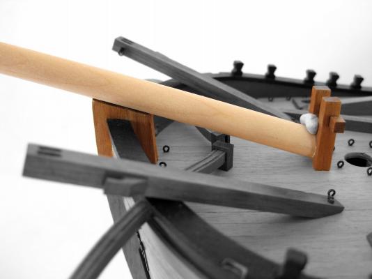
Hi Ken, thanks for that, much appreciated. Definitely will have questions about the masts also As discussed earlier the best solution was to trim the top of the stem down to the bulwarks rail. I used a carpenters square placed on top of the stem and slid the rule down to the rail to keep the correct angle and set the depth. Then a craft knife was used to score a line against the end of the rule to mark the cut line. I was concerned that using a saw close to the rails would result in them getting chewed up so needed to protect them somehow. I initially thought of using some layers of masking tape but was still worried the teeth would rub through this so ended up cutting and bending some 0.5mm brass sheet. Because of the position of the catheads I couldn’t fit the razor saw in so made the initial cuts with a hacksaw blade which was very slow as could only make very short strokes to prevent hitting anything. Once the cut became deeper there was enough space to get the razor saw in but was still restricted to making short strokes. Once I removed the top I used a file to clean up the surface and then wrapped some sand paper round the bowsprit and used that as a sanding dowel to put a curve into the stem for the bowsprit to sit in. The following photos show the curved sanded seat for the bowsprit and it in position. Okay, the above work dropped the bowsprit down to a much better position although the flat on the bottom of the bowsprit is still not as much as indicated on the plans but at least it now butts up against in the bitt in a better position. As it is right now it can’t go down any further as it hits the bumpkin end support which I already knocked a corner off for it to fit and to be honest if I left it as it is above I would be happy. But once I taper the mast down as indicated in the plans that will allow a bit more space between it and the bumpkin support so I will be able to further sand the top of the stem to bring it down further. Thanks for everyone’s interest and input. Cheers Slog

-
Hi Guys, Thanks for the nice comments. Glad to see you will soon be getting back to your Endeavour Rowand. Ken thanks greatly for the photos, much appreciated and gives me something visually to go by. Your Endeavour looks great, pity the log was lost in the great crash and we never got to see the finished article. Might be an idea to post it in the finished gallery so we can enjoy it in its entirety. Thanks again. Cheers Slog Hi Greg, thanks for dropping by. I am going to cut the stem back as much as I can to drop it. I think it will be a compromise between keeping the angle right and dropping it enough so the deck end looks correct without hitting the bumpkin supports. If it comes out looking as good as Kens photos above I will be happy.
-
Hi Ken, I would appreciate some photos greatly. I had a look at some of yours from MSW1.0 but they are a bit small, but it looks like your BS is shaped exactly like the plans and fit in the space properly so more photos would be helpful. Cheers Hi Edward, I just had a look at some more of the plan sheets and it appears that the top of the stem is flush with the rail which means the best way I think would be to chop off the top of the stem as close to the rail as possible as per the photo below and fix any damage that may (will!!) occur. Hi Steve, was busy replying above and decided Option 2 would be the best way after all when your reply came in LOL Cheers Slog

-
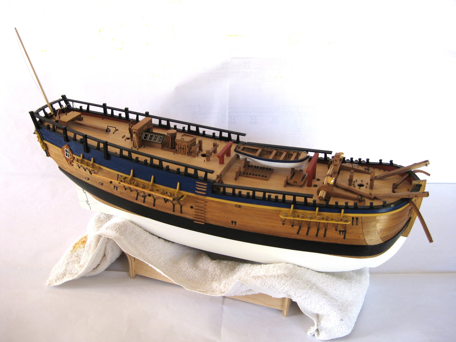
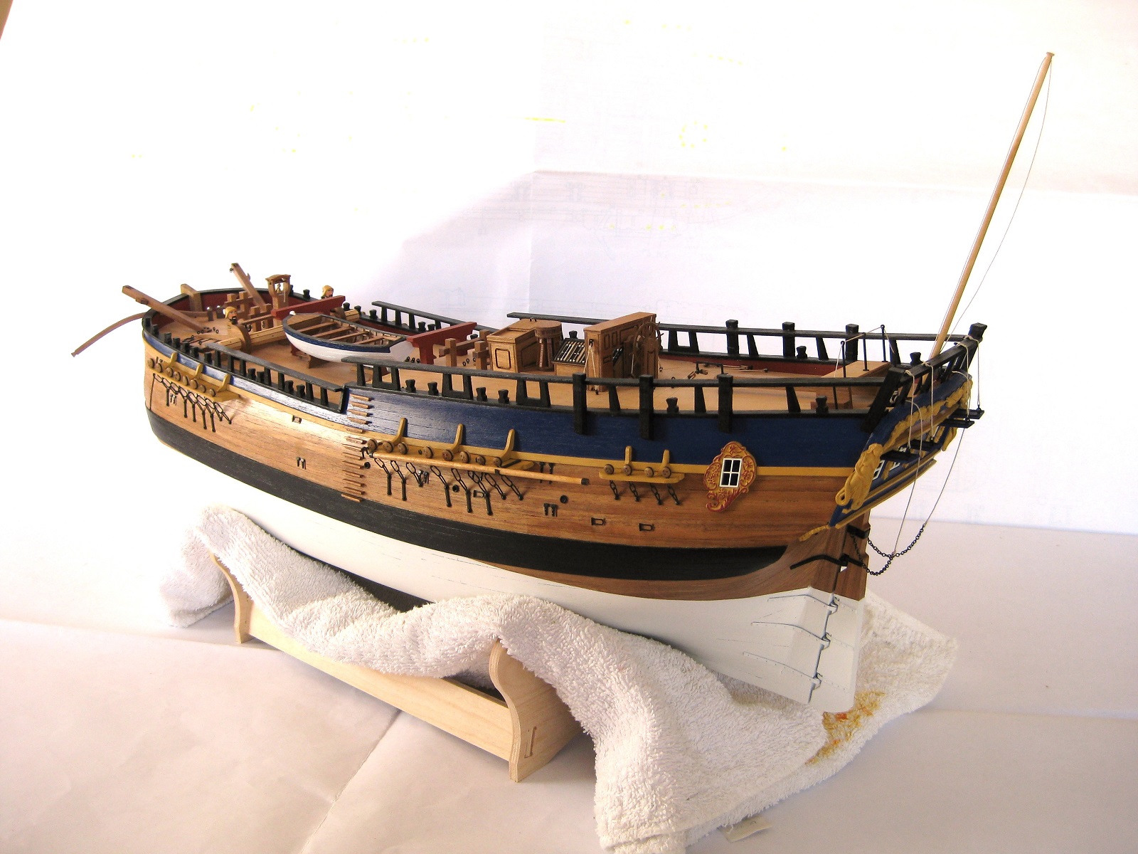
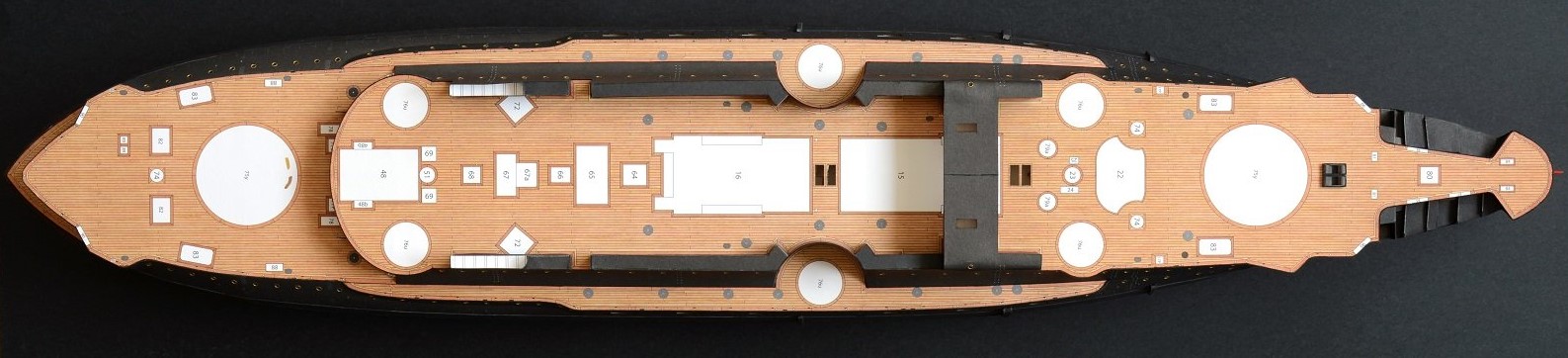
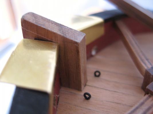
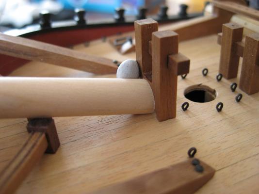
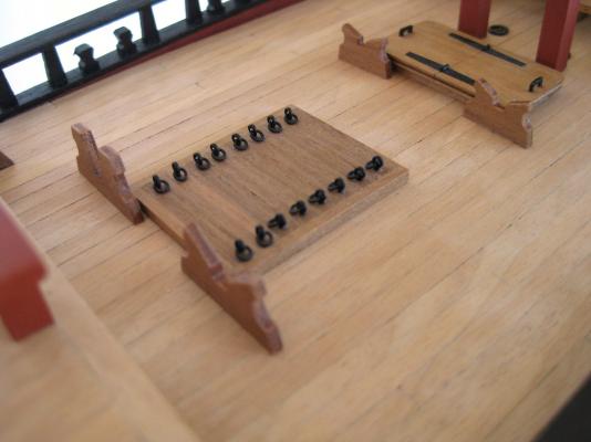
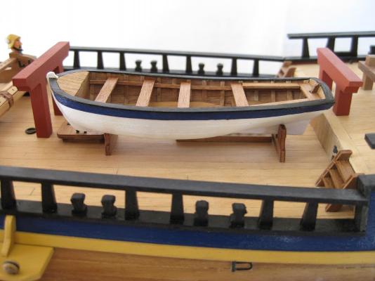
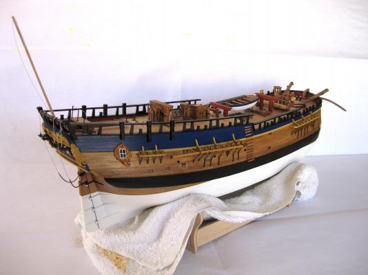
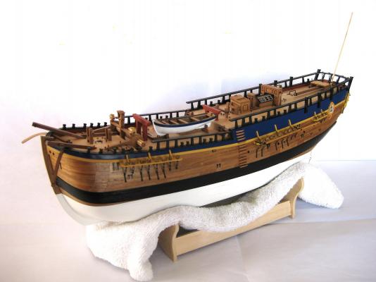
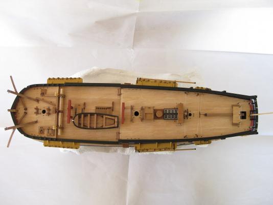
Thanks Duff, Mick, Sam and Jeff for the comments and everyone for the 'Likes' Although not perfect I am pretty happy with them but as usual lessons to be learned. Hi Steve thanks for the comments, after reading your comment I checked the AOTS and you are correct of course I see the stocks should be square on all sides between the inner banding. I also notice that I could have made the paper banding half the width the plans say to look more correct. I really need to remember and check the AOTS as I work on things Well this update is pretty disappointing as despite having 6 days home alone with no one to bother me I only did the ships boats cradles on the middle deck and a half arsed start on the bow sprite (more of which later) what a waste of a good modelling opportunity . The long boat sitting on the cradle was completed a couple of years ago waiting for this day Photos 3 to 7 are included for no other reason than to provide some encouragement to me as enthusiasm is starting to wane a bit. I mentioned above about the bow sprite, I came across a bit of a problem as can be seen in the photo below. The top of the Stem provides the correct angle for the bow sprite but as can be seen the end of the bow sprite (BS) hits the bitts to far up. The BS should be flattened on the bottom to hit the deck and have a notch to go into the bottom of the bitt. I think this must be a problem with the kit and not my error because if I move the bitt back to allow the BS to contact the deck properly then the bitt will be to close to the foremast hole or even over it. The foremast hole is predetermined so I couldn’t have messed that up. I have 4 options as I see it; 1) Leave as is 2) Cut the stem down to bring the BS down 3) Cut a rectangular slot in the underside of the BS to bring it down 4) Cut/file a circular groove into the top of the stem to bring the BS down Personally option 2 is out as I don’t think I can do it without getting the angle wrong or damaging near by components. Option 1 is easiest obviously and probably wouldn't have been noticed except by the most eagle eyed of you. I think options 3 or 4 would be most satisfactory way to do this but bear it still won’t bring the BS down as far as the plans show but the end of the BS would be better positioned against the bitts. Any advice or thoughts on this would be appreciated. Cheers Slog


-
Hi Doug, What a beautiful clean and sharp build this is. Real nice. Cheers Slog
-
Hi Candice, With regards to Bulkhead #6, I would double check that the bulkheads haven't been mixed up as looking at the photo it appears to be a good few mm to high. I wouldn't have thought Caldercraft would have got the basic hull layout so wrong as the ply and machining (in my Endeavour at least) is very good. Anyway might be worth going through the plans and the sheet layout diagram again to double check. Cheers Slog
-
Hi Steve, Your mast and tops look nice and crisp. Will be very helpful when I get to that stage. Cheers Slog
-
Hi Ron, The Endeavour has such a sturdy looking hull don't you think. For my planks I used 100mm which at a scale of 1:64 comes out about 21 feet full size. Yours will obviously be longer being a larger scale. I think what Alistair and Ken mentions above would be right. Cheers Slog
-
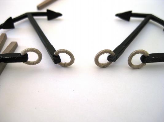
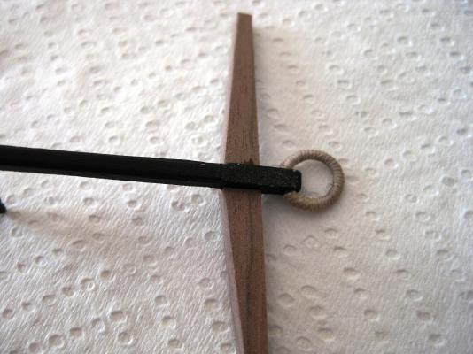
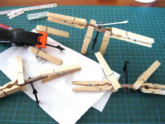
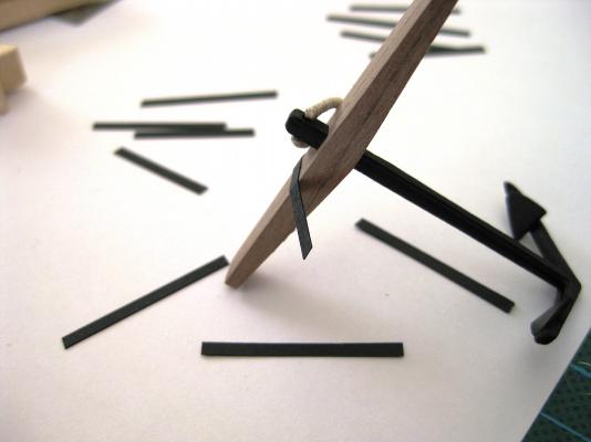
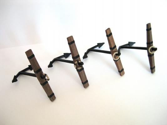
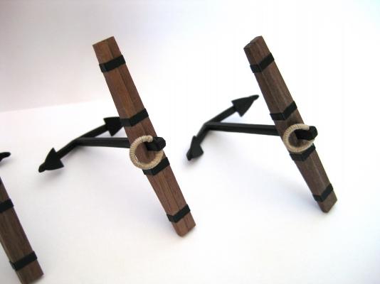
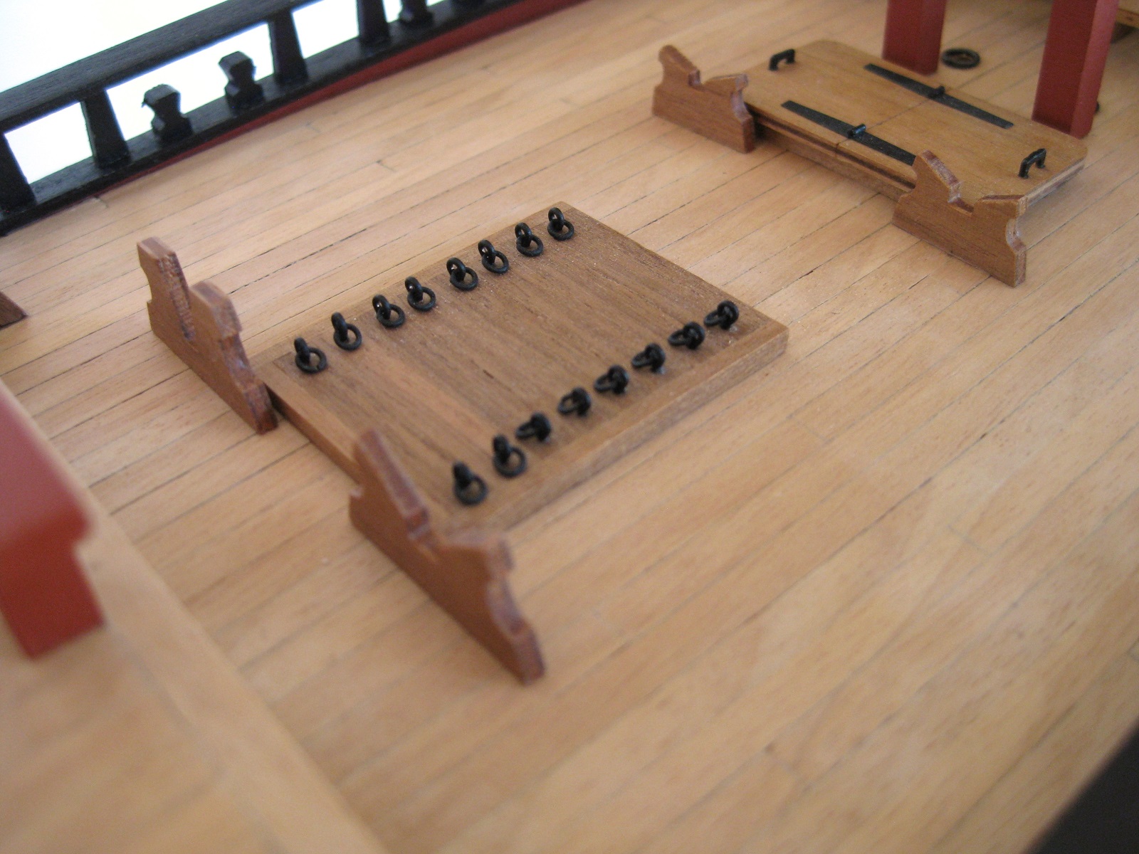
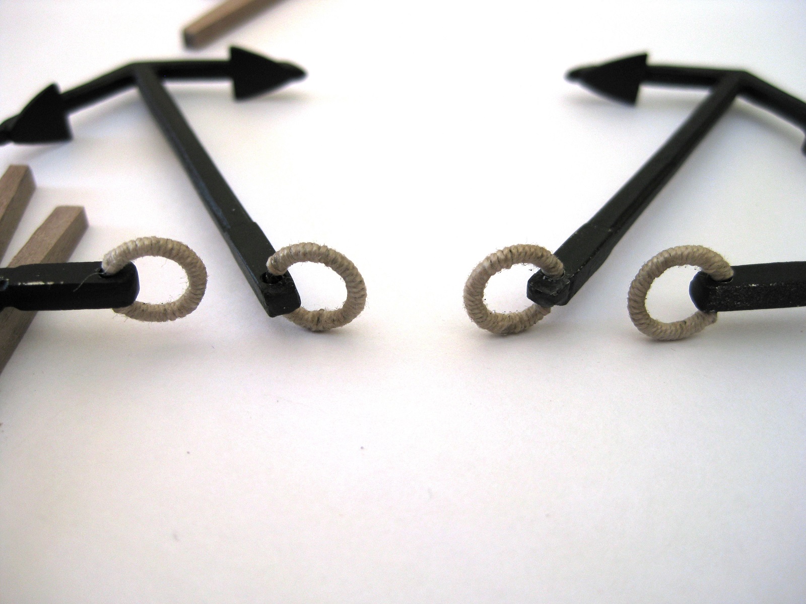
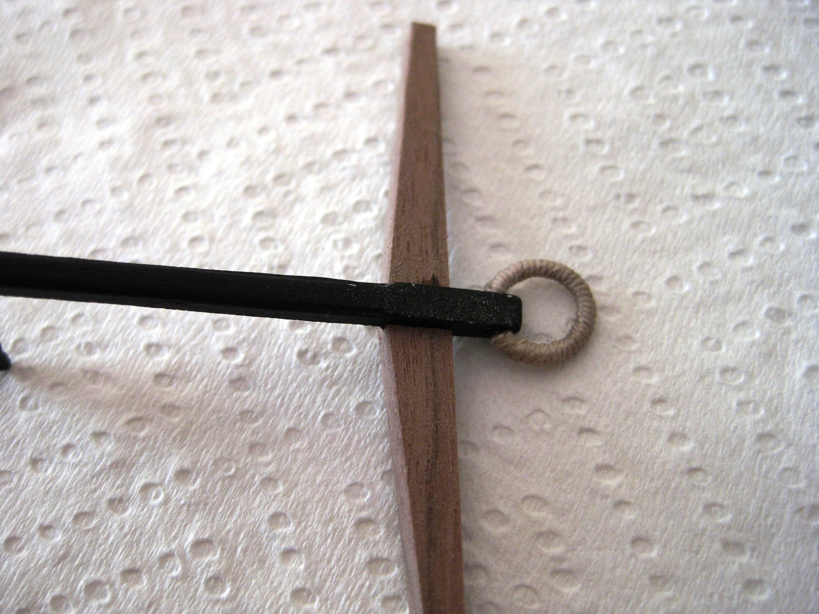
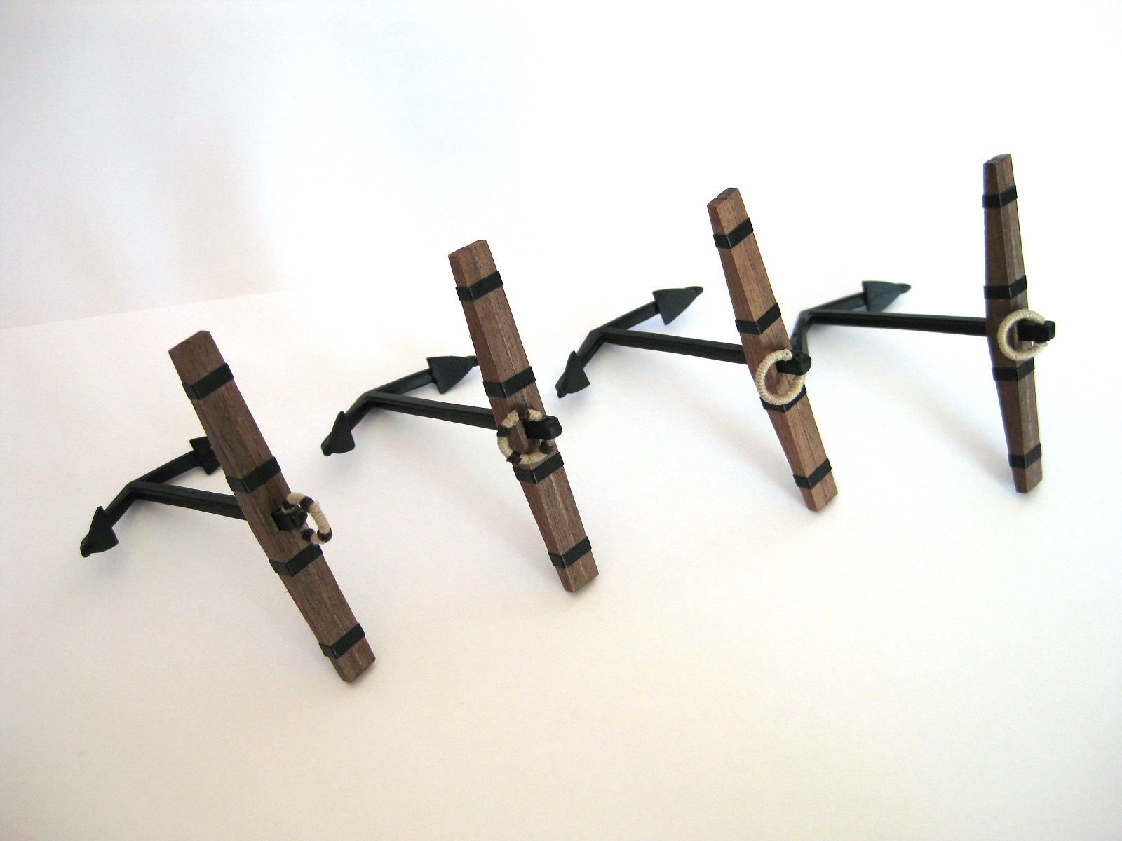
Hi guys, Well finished my anchors today. Still a bit unhappy with the puddening though. I cut off the puddening and the additional whipping from the last post and started again. I feel got these done a bit better than before and to be honest I think these are as good as I am gonna get them. I tried to do the whipping again and after doing 2 anchors (8 whips) I gave up on them. To be honest the time spent on them for mediocre at best isn’t worth it as I can’t get them looking acceptable so only did 2 and left off the other 2. I used CA glue to start and finish the puddening and then when finished waved the rings over a cigarette lighter to remove the fuzz. It also darkened the thread a little which is fine. To attach the stock halves I applied CA glue to recess on one half and positioned it on the anchor shaft. Then using PVA coated the other half and clamped together The plans say to replicate the iron banding with the black cartridge paper cut to 2mm wide strips. I used PVA applied with a brush to the paper and pressed into position and continued my way round the stocks. The plans don’t mention any dimensions so after a look at the plans and the AOTS I settled on 5mm in from the ends and 5mm out from the anchor shaft. All finished, as can be seen there are 2 with whipping and 2 without. I will get over it. The stocks and ‘bands’ were given a couple of coats of wipe on poly (applied by brush) and then went over the shafts touching in any scrapes and scratches with metal black paint. Cheers Slog