DONATION DRIVE - SUPPORT MSW - DO YOUR PART TO KEEP THIS GREAT FORUM GOING!
×

Captain Slog
-
Posts
904 -
Joined
Content Type
Profiles
Forums
Gallery
Events
Everything posted by Captain Slog
-
 Hi Adrieke, your steering house looks very sharp! Cheers Slog
 -
Hi Bob, your deck looks incredible! Cheers Slog
-
Hi Jeff, Your second planking layer is definitely showing the effort you are putting into it. Looks very clean and tight. I hated doing second planking with a passion What is the dimensions of the planking strip? Cheers Slog
-
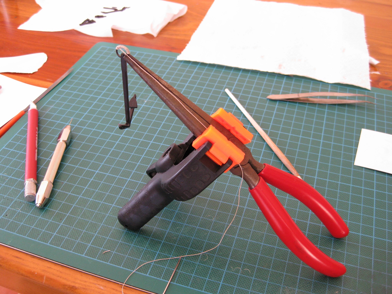
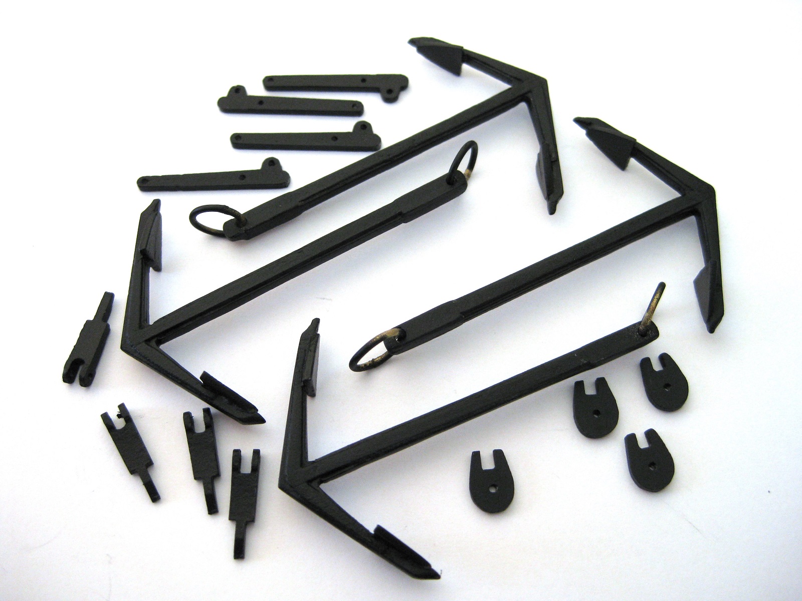
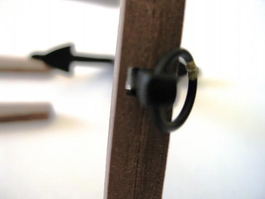
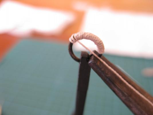
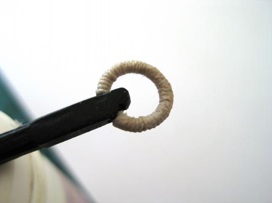
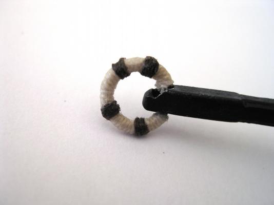
Hi Jeff,I have a 30w soldering iron and some electrical solder so will try that the next time I have any soldering close to possible melting material! The anchor ring isn’t under any stress so CA will do. Thanks for the comment Mick Hi Sam, I might try solid brass rod and take slices off the end as needed. I was also wondering about trying Evergreen or equivalent styrene sheet to cut the sheaves from as would definitely be quicker and easier to cut and trim. A quick paint, as obviously can’t blacken them and they are done. For all you can see of sheave once its in place I think it may be a viable alternative. I may try that also. Hi Wayne, I have also drilled and cut grooves to simulate sheaves and have been happy with the result up to now, but because the davit had an open end sheave I had to fill the gap somehow. When I get to the masts and yards which I believe are dotted throughout with various sheaves I might try some other techniques and materials to see what works. A bit more progress with the anchors. I previously mentioned that the grooves in the anchor stocks were to deep so here is a dark and blurry photo to show the gap with the two halves together. To overcome this I glued in some 1mm walnut strip in to each groove in the stock, which then made the gap to small. It was a case of filing the grooves back in with a miniature file until the anchor shank sat deeper in the stocks. I was going to leave a gap between the stocks and bend the ends together like a real anchor but wasn’t happy with the way they looked so took some artistic licence and continue to file the grooves until the stock halves fitted together the full length. Next up was to do the puddening on the anchor rings. I used my pliers and a clamp as a kind of helping hand. With the puddening I found a thread on MSW which mentioned that 0.25mm thread would be suitable so that’s what I used. I have no idea how to start and end the puddening. I tried a dab of CA glue to fix the end to the ring then wound my way round. Once I got to the end I used CA again to fix it but not happy with this method. I also tried various media as I worked round the ring to hold the thread in place. Initially I tried using watered down PVA but this appeared to bulk up the thread. I also tried using Caldercraft Flat matt varnish which worked very well as dries invisible so used that. I would wind along a bit and then varnish then continue. Again I don’t know a way to secure the ends. I used brown Guttermann cotton thread to do the extra bits round the puddening (don’t know the term for this) but yet again don’t know how to start or finish. As can be seen in the finished photo the puddening itself isn’t bad and settled into a rhythm to do this BUT the start and finishing is terrible and lets it down. Also not happy with extra brown bits as my spacing went awry as well as being clumsily executed. I will cut the whole lot off and try again. If anyone has a method for starting and finishing the puddening I would like to hear from you. Cheers Slog

-
Ah, that makes sense, thanks. Cheers Slog
- 2,250 replies
-
- 2
-

-
- model shipways
- Charles W Morgan
- (and 1 more)
-
It would have overcome an issue I had on my current build and probably will fill the hull on my next. But would use cheap pine as it is a lot cheaper than balsa, locally for me anyway. Cheers Slog
-
The ships bell could do with a bit of a polish! Does anyone know what that "gun port hatch" is on the belfry below the bell? Cheers Slog
- 2,250 replies
-
- 1
-
-
- model shipways
- Charles W Morgan
- (and 1 more)
-
Excellent idea John, thanks If PVC is good enough to transport water through my house for decades, its good enough for a model IMHO. Cheers Slog
-
Hi Jeff, What a difference with the sides on and the gun ports cut out, real nice! Cheers Slog
-
Hi Greg, Your rigging looks incredible
-
Hi Ron, Been a while since I dropped by and all I can say is WOW. Sails look fantastic. Nice work. Cheers Slog
-
Thanks Grant, I just sprayed coke all over my monitor
- 2,250 replies
-
- 4
-
-
- model shipways
- Charles W Morgan
- (and 1 more)
-
Hi John, Your build is coming along nicely. There is a very high chance the MS Charles W Morgan will be my next build eventually. I may have missed this but is the anchor chain in the photos the MS supplied chain? Cheers Slog
- 2,250 replies
-
- 1
-
-
- model shipways
- Charles W Morgan
- (and 1 more)
-
Hi Pygothian, I have been keeping tabs on when your Syren would arrive since my next purchase at some stage is likely to be a Model Shipways kit from Model Expo and being a fellow Perthite was interested in your experience. Well doesn't sound to impressive from your comments! My Endeavour took just 6 days from the UK door to door! Anyway happy building and will be following your build. Cheers Slog
-
Hi Kevin, You are off to a nice start. I will definitely be following this one. I would love to do this one at some stage but I have the 1:200 GPM card one on the back burner at the moment. Interestingly I started at the same area you did. The funnel is such an interesting area. Not sure if you would be interested in the following link if you are not aware of it already but it is by Anton (Perth_shipyard) who used to be very active on MSW 1.0 with his HMS Diana. Anyway he is using the KA 1 upgrade kit which I think you are/going to use. http://www.shipmodels.info/mws_forum/viewtopic.php?f=59&t=144178 Cheers Slog
-
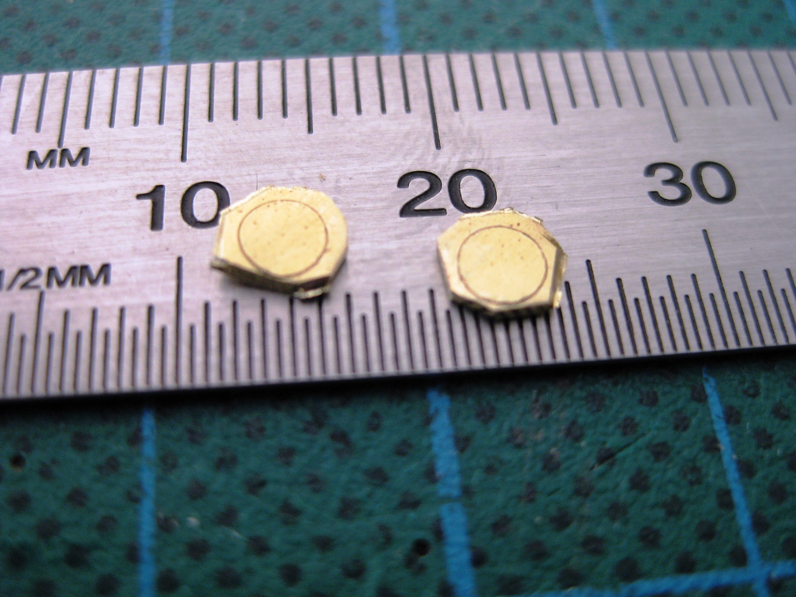
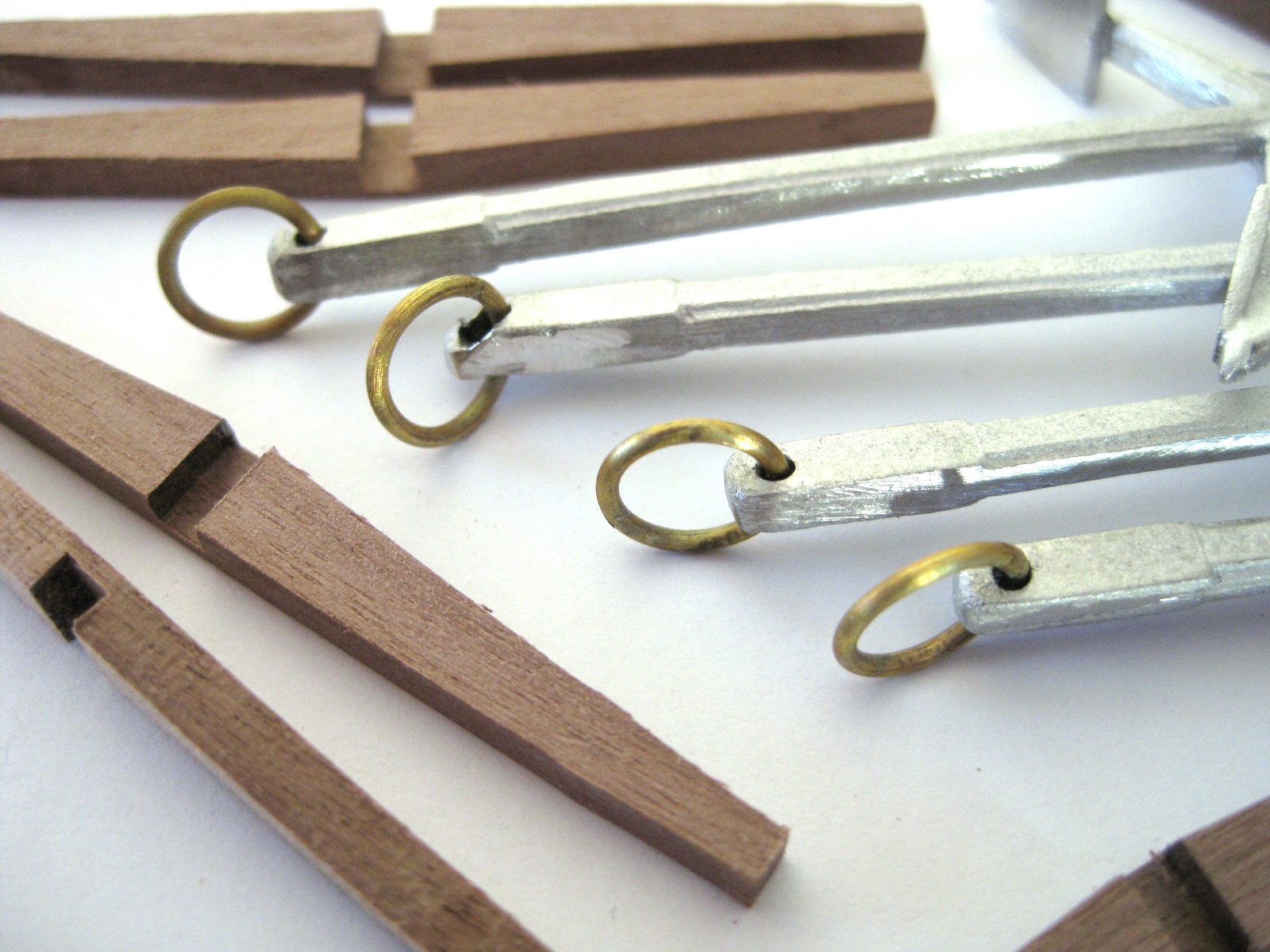
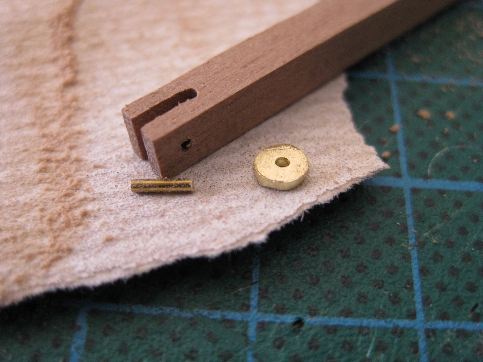
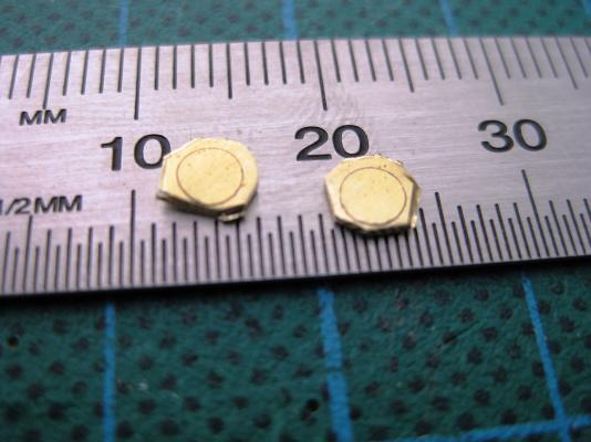
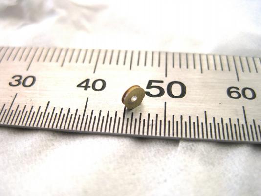
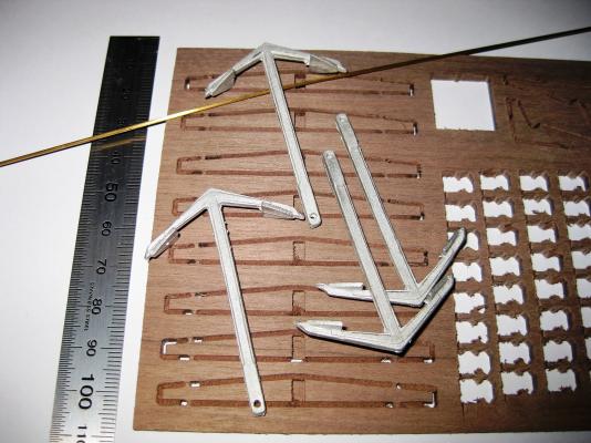
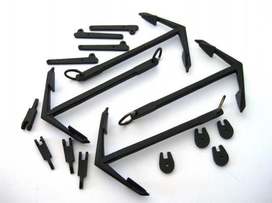
Hi, Greg and Duffer thanks for the kind words much appreciated. Jeff, when I read this I had a real “oh…!?” moment and rushed to the plans but no mention of a supplied sheave, whew! Yeah you would think it would be a supplied part. Hi Sam, thanks for the suggestion and I tried it out this morning. Using a 3mm hole punch I tapped it against the brass sheet to scribe the circumference and using tin snips and side cutters trimmed the excess off as best I can. I marked up 2 in-case of mess ups. Then after drilling a 0.8mm hole to match the rod I soft soldered the rod into the hole. Trimming the rod quite short I placed it in my Dremel and using only the first 2 settings on the speed range fired it up and held a file against the edge. Slow and steady was the order of the day. At one stage I pressed to hard and bent the rod but was easily pushed straight again. Once that was done I wondered if it would be possible to put the groove in? So fired the Dremel up again and used a miniature triangular shaped file pressed against the 0.8mm edge of the sheave. This was a bit hit or miss as the file would sometimes skate off the edge removing the bevel it just made! IT was quite difficult to remove the rod afterwards though and needed to re-drill the hole. Thinking on your idea and other possible solutions I wondered if it would have been easier to buy 3mm brass rod instead but then have the issue of cutting off a 0.8mm slice. Okay, after messing around with tiny parts moved on to something a wee bit bigger, the anchors. Photo shows the required parts. 4 cast metal anchors and the stock halves from solid walnut sheet. The 1mm brass rod is needed for the anchors rings. Okay, a small issue from CC and a near disaster by me which I wasn’t sure if I should mention due to my stupidity but decided to share anyway. Got to show the good the bad and the ugly I suppose. Firstly I cleaned up the minimal casting flashing on the anchors with some files and cleaned up the holes with a 1.5mm drill. Then cut out and trimmed the walnut stock halves. Here is the first issue; the grooves cut into the stocks are too deep. When the halves are pressed together around the anchor there is a considerable gap. I think I will glue some 0.5mm strip into the bottoms of the grooves and see how that works. The brass rings are from 1mm as per the plans but they don’t say what diameter. After some measuring and checking I bent the wire round a 6mm diameter drill shank and I think they look okay size wise. Here it goes . I thought I would silver solder the rings together after feeding them into the holes in the anchor. I placed the join as far from the anchor as possible and used the torch to come in from the side to keep the heat away. Well it turns out the melting post of the cast white metal is well below the melting point of the silver solder and started to melt. Thankfully I removed the heat quick enough and didn’t loss the end of the anchor as the ring started to morph its way through the casting. After squeezing as much material back into the space, tidying up with files and re-drilling the hole. The saved anchor can be seen second from the top. Not to bad as could have been a lot worse I ended up using CA glue on the ring joins which will be hidden in the anchor hole. Painted the anchor castings and the pump components using Games Workshop Chaos Black spray. Not to worried about the rings as will be doing puddening on them next. Cheers Slog

-
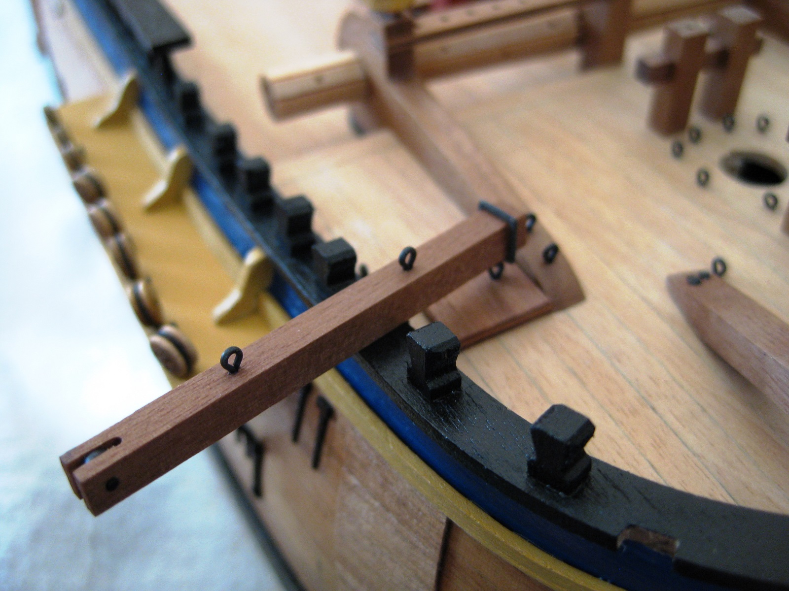
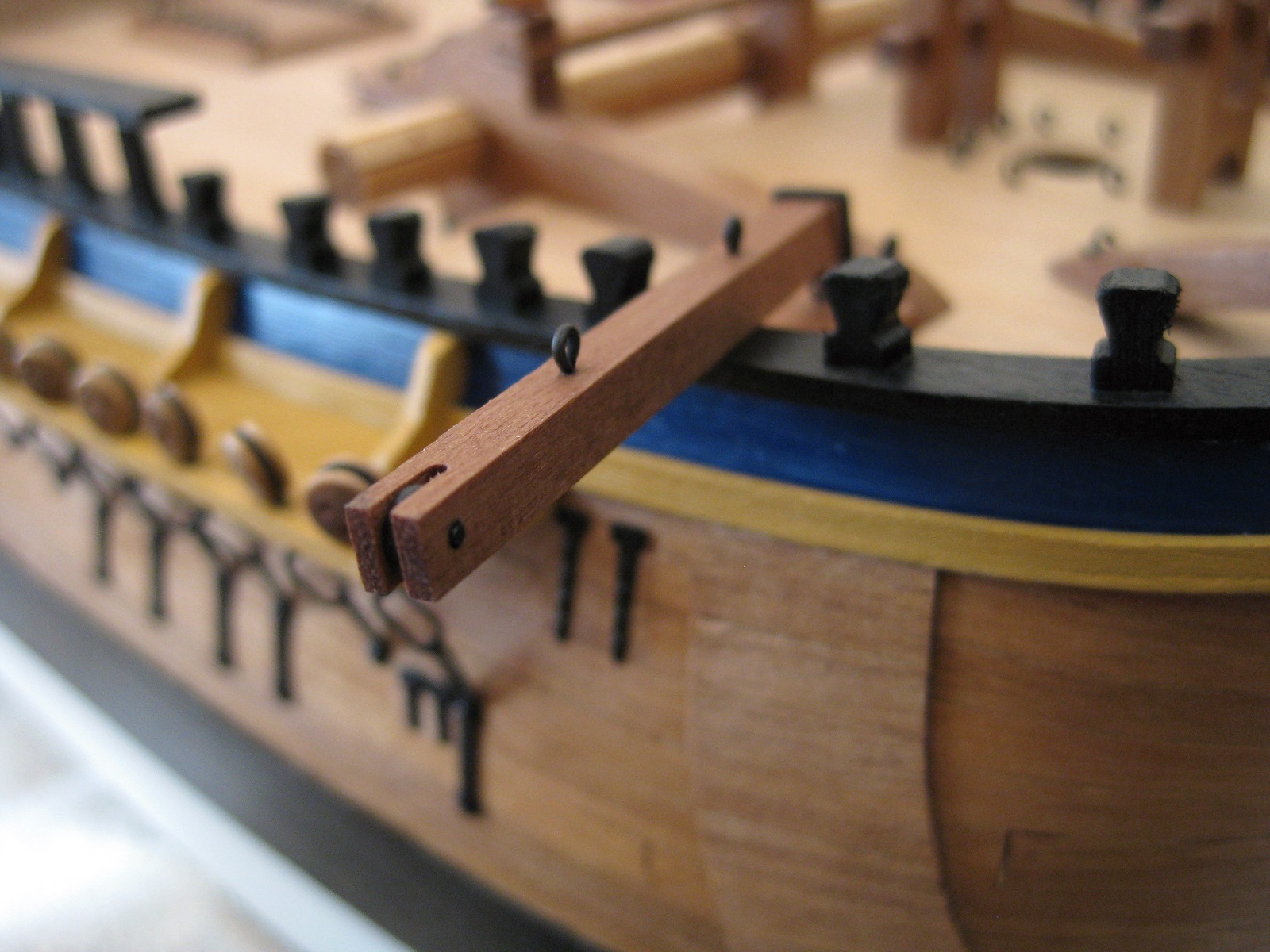
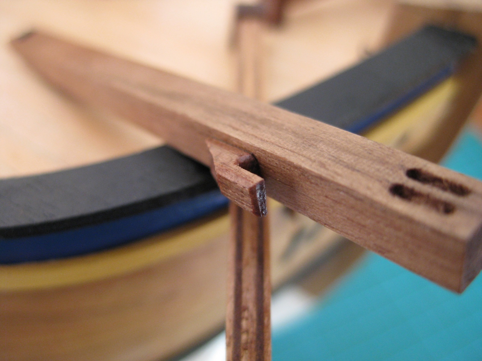
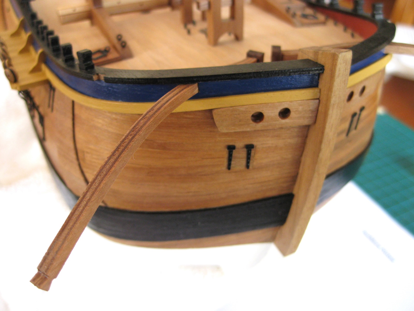
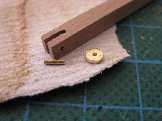
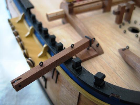
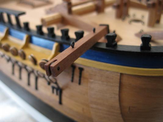
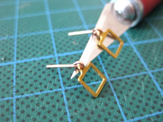
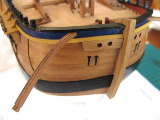
Hi, Just a small update today, the fish davit. This is shown in the AOTS and provided by Caldercraft with an open ended sheave. The part is supplied from one of the solid walnut sheets which is very cleanly cut by CNC including the open sheave. I had to wait until I bought some 0.8mm sheet brass to make the sheave. It was actually quite difficult to cut the sheet and make a round 3mm x 0.8mm sheave but since most of it is hidden inside the davit I got it round enough. I used 0.8mm rod for the pin. I chemically blackened the sheave and pin but for some reason the blackening didn’t take to the brass sheet. I wonder if the brass composition of the sheet is different from the rod which I have had good success with in the past. I also included a couple of eyebolts in the top surface as per the AOTS. The davit is just shown in position for the photos but will be removed later as it sticks out a fair bit. I will pin it to the rail when the time comes. Cheers Slog
-
Hi Jeff, really moving along now! Are you going to paint the hull, in like the Trafalgar colours or going with the natural look? Cheers Slog
-
Thanks Jeff. Never thought of just doing one . I think I will do that and see how it looks. I think I will need to paint the cast white metal parts though as don't think the blackening will work on them. Thanks Ferit, I will leave the bumpkins with the varnished finish. Unfortunately they are built up with ply pieces which kind of stand out but happy enough with them. I couldn't decide whether to paint the cat-heads black or leave varnished but 99% sure will leave them as is also. Good advice Greg. I will leave off things like anchors which will catch sleeves etc but the cat-heads etc don't stick out to much and pretty solidly attached. Hi Mick, most references, including the AOTS show them on the rails. I think only CC have them going through the bulwarks. Seems to be dispute whether Endeavour had them at all but I like the look of them so decided to go with that and stuck with the kit method also. "Someone did tell me what it's called but I have slept since then " ROFL It gets a bit like that sometimes. They are called thumb cleats and redid them today and glued them on. Photo below. Cheers Slog

-
Hi Edward, You are progressing well. Have a question regarding the planking at the top rear of the quarter deck next to the stern? You appear to have a large single sheet of wood? Is this what Caldercraft supply now to do that area as I had to plank mine in the usual way. I assume you will trim it down in height as from the photos it does appear to be quite high above the rear deck. Cheers Slog
-
Very nice Ferit. Everything looks nice and square and symmetrical. Good to see overall shots now and again. We tend to get focused on the details and forget the big picture. Cheers Slog
-
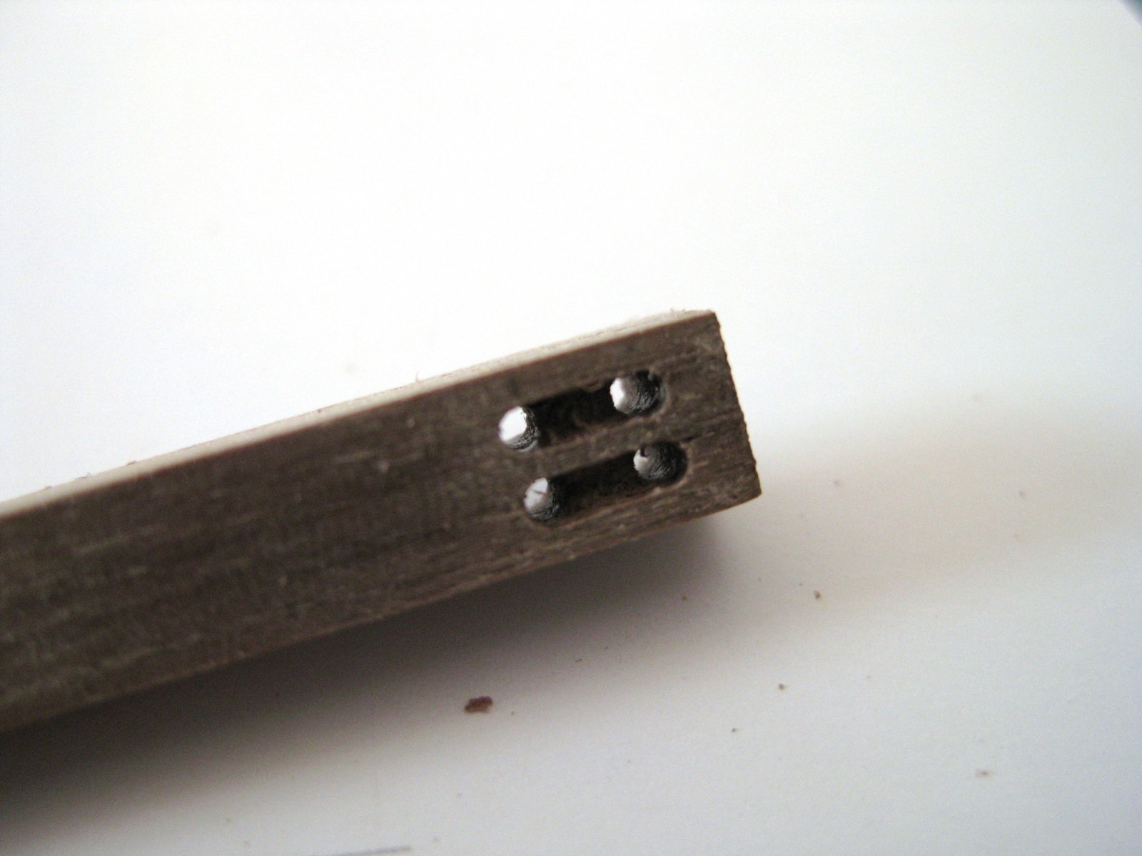
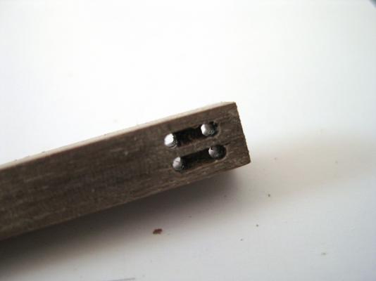
Hi Mick, Your choice of colours for your guitar should look real nice. Greg and Tom answered your questions but might add that probably easier to fake the mast sheaves with a couple of holes and a groove. I did 0.3mm holes and groove in the 2mm ensign staff and today did 1mm holes in the cat-heads. Once you drill the holes use a steel rule and a new No.11 blade with a sharp point to score a line between the outside edge of the holes, joining the two. Doesn't have to be deep then use the point of the blade to pick out the material between the scribe marks. For the 1mm holes I also used the point of the drill at a shallow angle to 'scrap' up and down the groove by hand to clean the edges. Didn't with the 0.3mm for fear of breaking it. Cheers Slog
-
Hi David, Beautiful build. Look forward to your next one. Cheers Slog
-
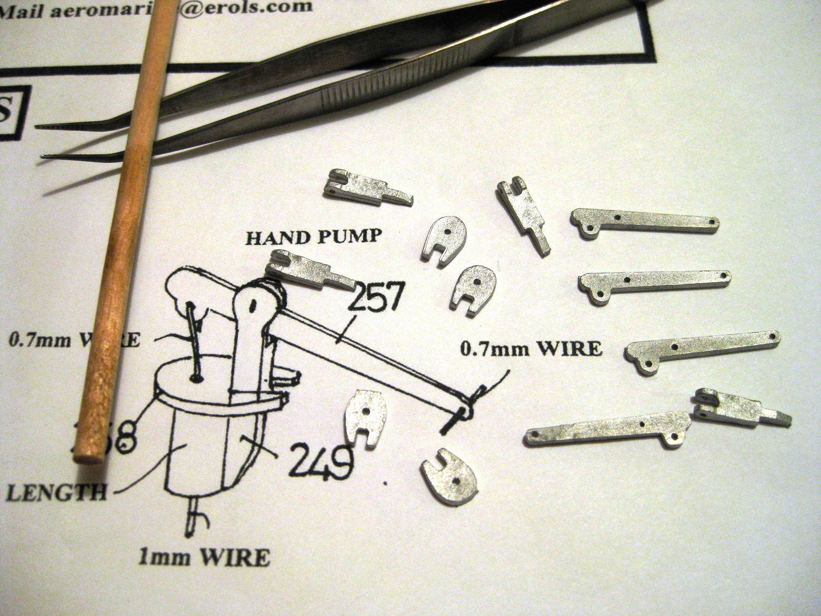
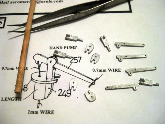
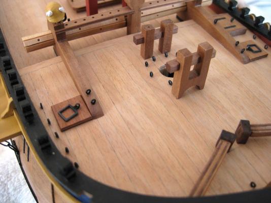
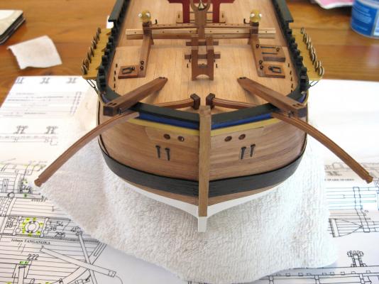
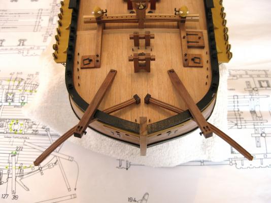
No worries Sam, I assumed it was a mix up . Thanks for the info on the wire. As mentioned up above I decided to do the pumps but after seeing Mikes scratch pumps and then checking Steve’s and Greg's who also scratched the pumps I set them aside until I decide what to do. The photo shows the cast white metal components which are quite chunky. The castings themselves were of decent quality needing only a touch up with a file to clean off some casting seams. The other parts needed are 4mm dowel and 0.7mm brass rod. Hmmmmm decisions decisions… While I procrastinated about the pumps I decided to move to the bow, since the rear deck is hung up on the pumps, the mid deck is hung up on the ships boats and cannon, I am running out of areas to work on LOL. First up is the fish davits. Caldercraft supply 2 davit pads and 2 shackles but only 1 fish davit. Not sure if the real ship had only one davit that they humphed from side to side? Any way the davit pads are 1.5mm walnut ply which after cutting free from the sheet I sanded a slight round on the top edge as per the AOTS and stuck down with CA. The davit shackles are photo etch brass. The plans don’t mention how they are secured to the deck but the AOTS shows them attached to an eyebolt so used the supplied copper ones. The shackle needed the hole enlarged slightly with a drill to accept the eyebolt and after opening the eyebolt slightly to accept the shackle it was squeezed closed again and the parts chemically blackened. The fish davit pads and shackles in place. I haven’t done the davit yet as it has an open sheave so need to come up a sheave to fill the slot. The bumpkins were up next. Away back when I was doing the bulwarks and before the top rail was down, I marked the position of the bumpkins and cut slots into the bulwarks ready for this day. There was a fair bit of discussion in MSW about the position of the bumpkins and how they should be placed over the rail, or even if the Endeavour had bumpkins, but this is how the kit shows them so happy to go along with this set-up. Once the 2 halves of the walnut ply bumpkins were glued together and a final sand to clean them up they slid through the previous made slot into the solid walnut brackets which were CA glued to the deck. The cat-heads next. I was swithering whether to cut full slots and make up and insert proper sheaves but again a lack of suitable material at hand decided for me so made false sheaves by drilling 1mm holes right through the cat-head and after scribing lines joining the holes the material was picked out with the craft knife. A couple of photos of todays work. I notice most people paint the cat heads black but decided to varnish first so that the securing bolts and ringbolts on the side (this is not mentioned in the plans but is in the AOTS) stand out more. I still have the thumb cleats on the sides to do (again not in the plans but is in the AOTS) as I was almost finished them when “one little trim needed to finish" caused one to break apart. I may go back and paint them black but will see. Cheers Slog
-
Hi Mick, Masts looking great. My vote would be for a green guitar top. PRS did a beautiful green quilted maple top as part of there range which I fell in love with. Are you going to use traditional aniline dyes for staining your guitar? Cheers Slog