rwiederrich
-
Posts
5,520 -
Joined
-
Last visited
Content Type
Profiles
Forums
Gallery
Events
Everything posted by rwiederrich
-
Thanks everyone for the fine comments and likes. I stopped waiting to receiver a concrete confirmation from any museum. Rob
-
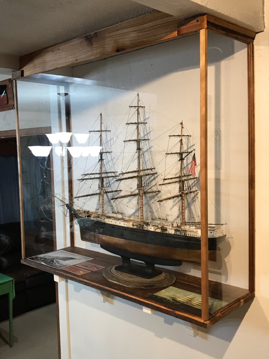
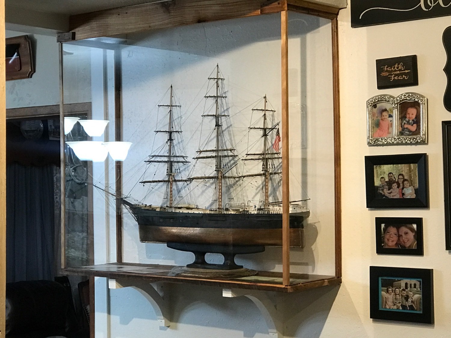
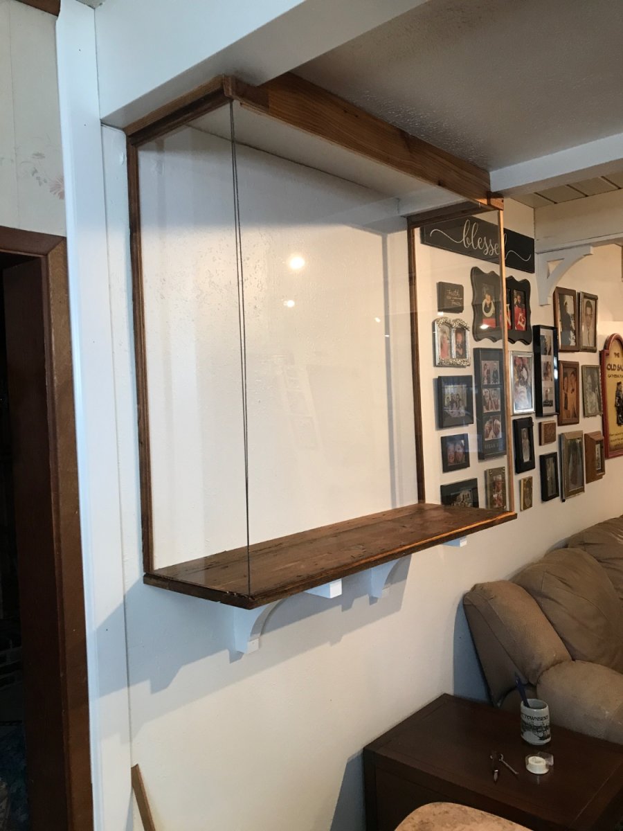
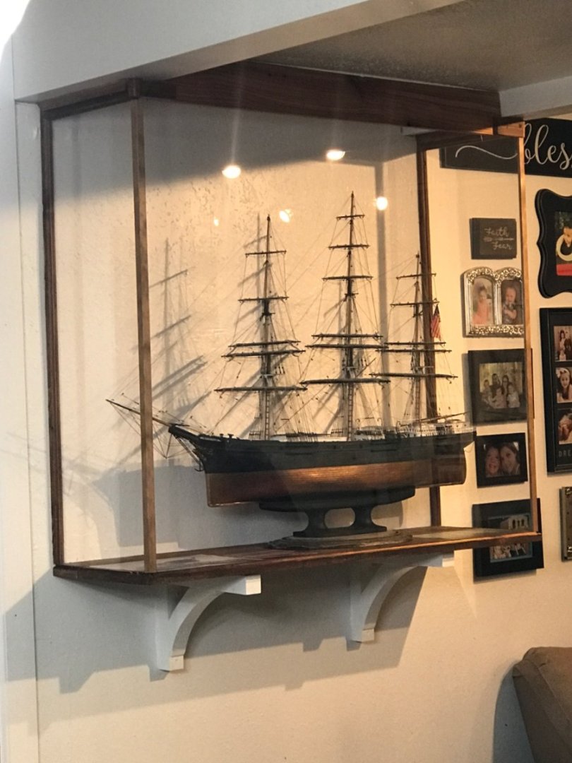
I built the shelf brackets to be exactly like the main beam brackets in the living room. I wanted the case to look original to the space, but still purposeful for the model. I think it looks good and the model is now protected from dust and Cobb webs…..and prying hands. I wanted the model to be easily viewable, so I intentionally kept the case as low as possible. LED track lights from both rooms amply illuminate the model. Rob
- 3,560 replies
-
- 3
-

-
- clipper
- hull model
- (and 2 more)
-
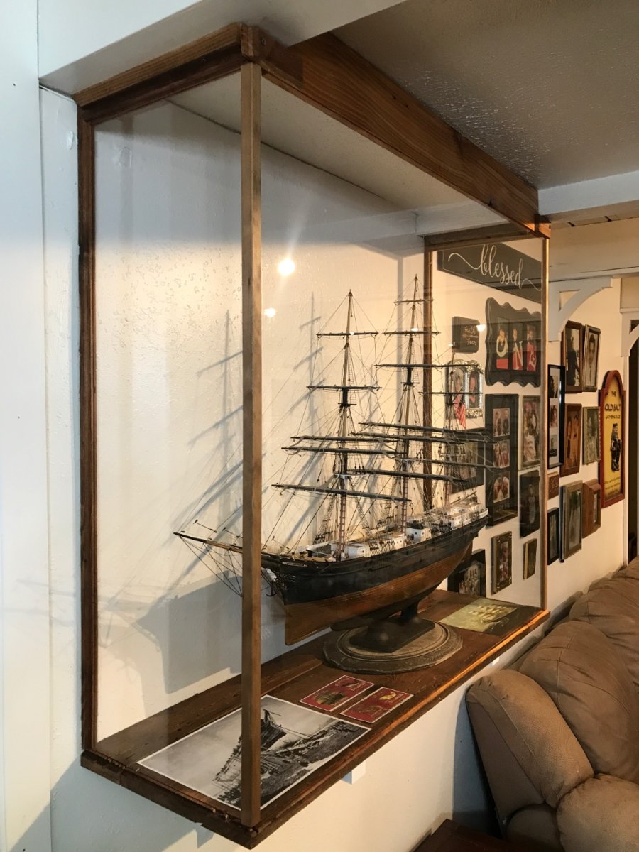
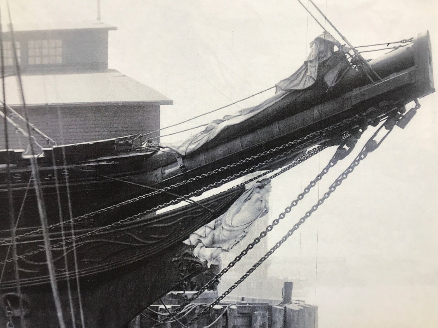
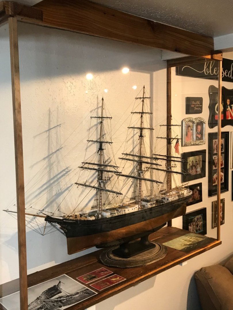
Finished the case and filled it with the model and some historical images. Here’s some images.


- 3,560 replies
-
- 8
-
-

-
- clipper
- hull model
- (and 2 more)
-
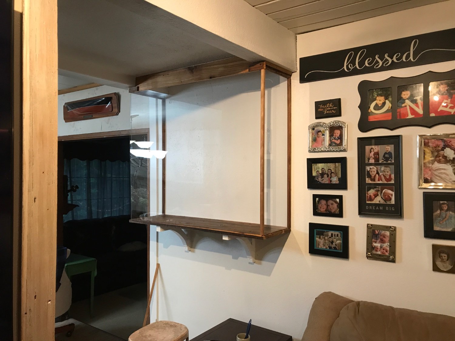
Here are a few construction pics of the new case. Still have trim to add. I used 100 year old cedar for the construction. It was grown about the time Glory of the Seas was burned. A fitting symbol of one life began as another was ending. More images to follow today. Rob


- 3,560 replies
-
- 6
-
-
- clipper
- hull model
- (and 2 more)
-
Building a new case for Glory of the Seas. It will be from the ceiling down. A big case built in. It’s late and I worked on it all day……so no pics till tomorrow. Till then. This means I have her existing shelf for another clipper……. Rob
- 3,560 replies
-
- 3
-
-
- clipper
- hull model
- (and 2 more)
-
I'm glad you are on the mend. Clippers, as you may know are my favorite design...and the Glory of the Seas is the best example of a clipper that has great connection to the PNW. I've even been to her grave and collected relics. Re-reading your log....I wish to reiterate, the corrections that Clipperfan has suggested to het cutwater and stem. I'll be watching. Rob
-
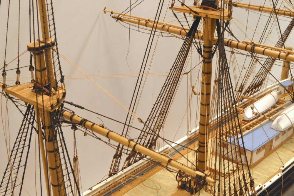
Rick, Large checks(cracks) would form on the best single sticks as they dry and put under stress. Banding them would be prudent if not economical. Still not Al builders banded their lower masts. Rob
- 3,618 replies
-
- 1
-
-
- young america
- clipper
- (and 1 more)
-
John….. I don’t want to mistakenly miss lead you or anyone. The Red Jacket was not a McKay clipper, so I would assume she probably didn’t have Naval hoods. I was pointing out the need for research on these matters, Flying Cloud was a McKay clipper and I might have erroneously confused the two in my eagerness to encourage good research. You have performed very well in contouring the solid wood hull. Rob
- 165 replies
-
- 1
-
-
- Red Jacket
- Marine Model Company
- (and 2 more)
-
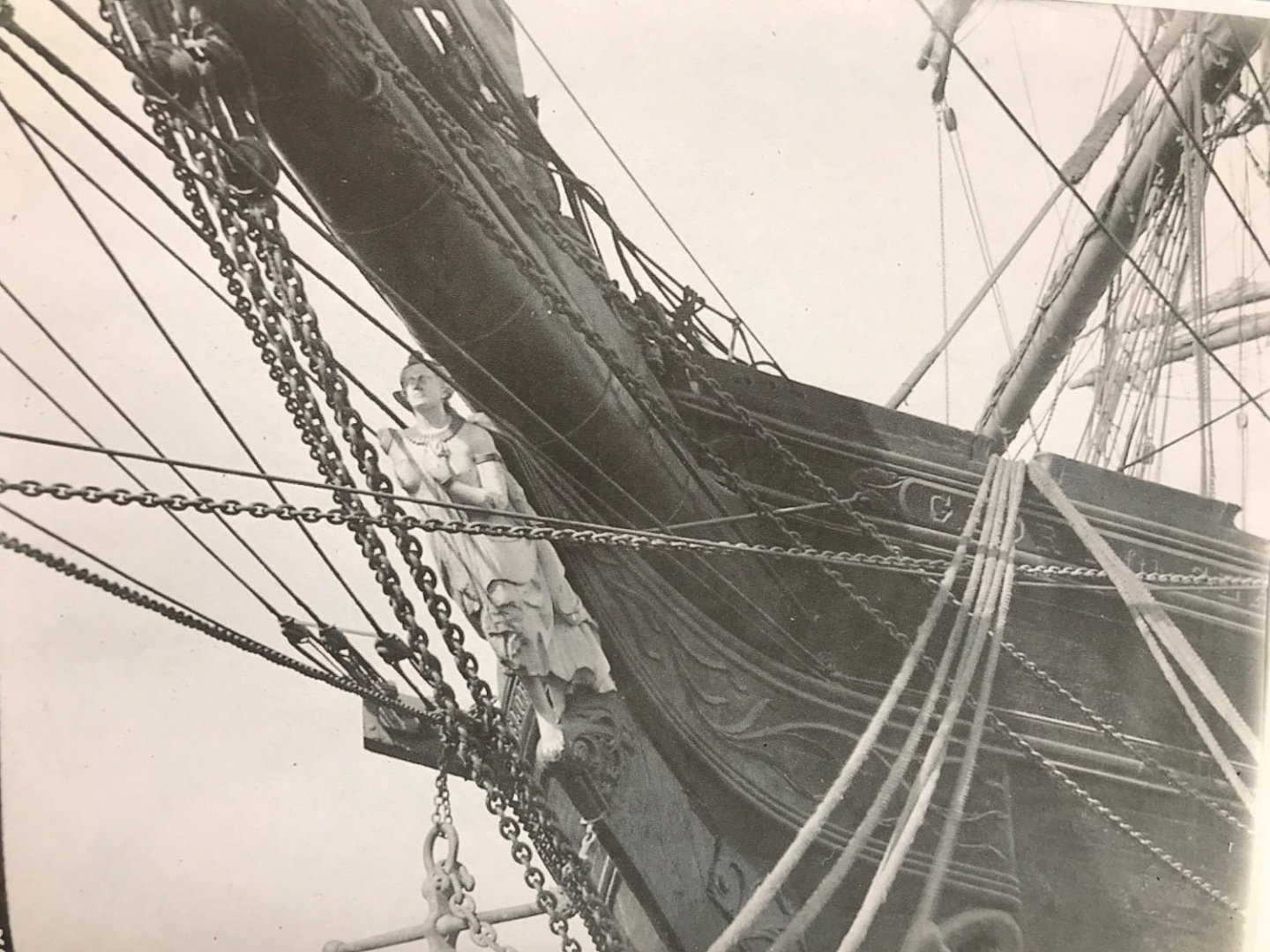
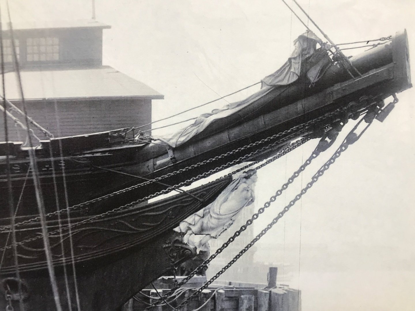
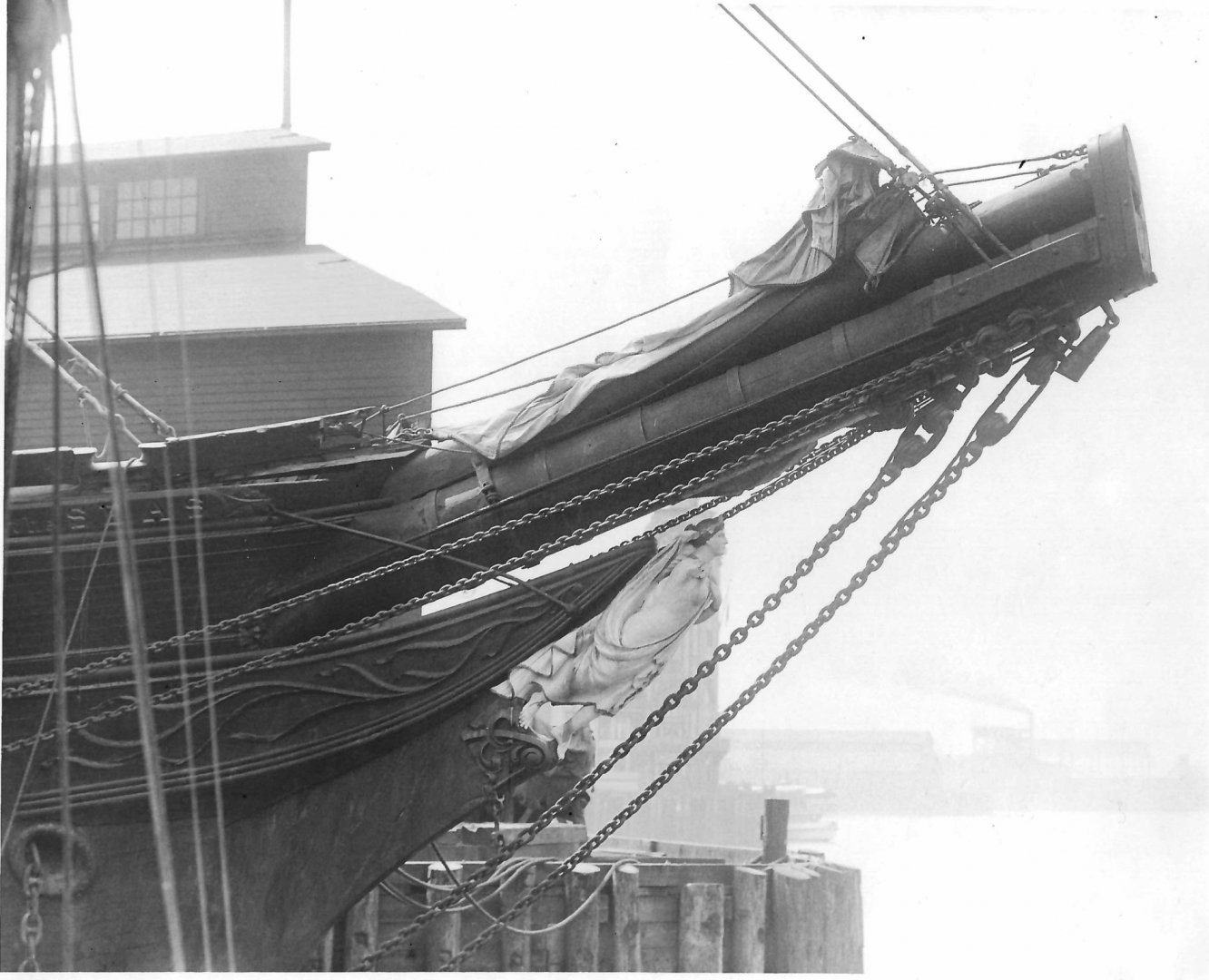
John…I’ll begin by posting some pics of McKay’s last clipper, Glory of the Seas. You can see the curved hood just above and behind the figurehead and under the bowsprit. This devise is described on his ships. And it is nearly depicted on all his clippers. It is what reinforced the stem and cut water. Rob
- 165 replies
-
- 1
-
-
- Red Jacket
- Marine Model Company
- (and 2 more)
-
John....I've been following your build...great job. One thing I hope you really consider and research, is Donald McKay's prolific use of the *Naval Hood*. A structural feature he utilized on all his clippers. Separating his designs from the average clipper. The Naval Hood can be easily seen on his last clipper, the Glory of the Seas. This is an excerpt from an email from Rich Jones a fellow McKay clipper researcher ; "Anyone reading this brief description by Duncan McLean of Flying Cloud has to ask themselves this question. Why would McKay abandon such a ruggedly constructed feature? "Her hood ends are bolted alternately from either side, through each other and the stem, so that the loss of her cutwater would not affect her safety or cause a leak." I believe the very fact that these exact features are prominently incorporated in his final medium clipper ship Glory of the Seas is proof of precisely the opposite: Donald McKay was consistent in maintaining this unique structure throughout his career. " I hope you will consider adding the Naval Hoods to your build...even though they are absent from your plans. Since Builder models seldomly replicated this feature due to the fact the builders model was designed to depict the Hull design(Dead rise/sheer) and not any extra feature. It is a well known fact Donald McKay kept this structural feature a secret, until his model was run down the ways. Rob
- 165 replies
-
- 1
-
-
- Red Jacket
- Marine Model Company
- (and 2 more)
-
Rich...I concur with Ed. Research...research. flying Fish was constructed in 1851...and by then large *sticks* were not as available on the East coast. Glory of the Seas was built with, *built* lower masts....on all three masts in 1869. However, by the mid 1880's she had several masts refit with large single *sticks*, while she was on the West Coast...where such large trees where abundant. Research the time frame of the said paintings....you may discover that if Flying fish was painted with bands on her mizzen...that was probably how she was rigged...during her construction...since most times good quality paintings were commissioned shortly after the ship was launched.....or after a new captain had made significant alterations. Ed's YA was built with a banded mizzen Rob
- 3,618 replies
-
- 1
-
-
- young america
- clipper
- (and 1 more)
-
Glad to see you posting again Rich. Life can be a struggle at times. I would love to see an articles emphasis on the differences of Glory, as presented over time. A good photographic comparison would be fascinating. Very few ships, (let alone clippers) can be represented with two separate models, that accurately depict the same vessel at different times of their evolution. Someone who stumbles on just one or the other representations (Models) of Glory , (without any back story), might conclude, that one of them is incorrect. I'm truly looking forward to the article. Rob
-
And none of this...NONE of it, would have been remotely possible if not for the help and aid of Michael Mjelde and the generous use of his extensive photographic collection. Not to mention years previous...I and Rich Jones, had already concluded we needed to correct the errors falsely identified as Glory's hull design. Previous models were wrong...even Mike's own drawings were wrong (and he came to know it). The entire adventure...began so many years ago......on opposite coasts of America. With Rich and myself wanting and concluding the same things. He found me and we, along with yourself, made it come to fruition. Thanks a lot Vlad. Now... what is your next move for your Glory? And beyond? Rob
-
Vlad.....I'm very glad you opted to finish her...and not leave her as a hull model. Funny thing is...you and I tackled our first versions of her with the same idea...to keep her as she was originally designed and built by Donald McKay. As we traveled this road...you kept on track..where I took another direction. My version being my second attempt...I went full bore...to see her as she was at her panicle. You've captured her wonderfully. *Keeping her decks clear*. One BIG identifying observation made at her completion....by Duncan McClean. You've stopper rigging her at a good point....not withholding any MAJOR rigging structure...but releasing you from the tedium of rigging her stunsails and all those bunt lines and blocks associated with them. I'm very impressed. There were times, as in my own experience, we had to make about faces and redo some incorrect work. It's fascinating to notice that you and I used some similar and many different means and techniques to accomplish the tasks at hand...and to enjoy the outcome. I am very proud of your accomplishment. I feel as if I almost *Talked* you into building her, as I tried to convince you that American clippers were far larger and more exciting and faster then their British counterparts. I feel I *Lured* you in. you did not disappoint. Thank you for helping me along with my own build...by extending your skills at CAD work and provide me with my own POB frames. A corroboration that crossed miles and cultures. I am indebted to you as well my friend. I hope this finds you well and this new year will provide greater opportunities for you. I can tell you...I am richly blessed because of our association. Rob
-
Great to see you back in the yard Keith I know the shroud rat line struggle very well. I build only clippers. Happy new Year and I’m looking forward to seeing you move ahead. Great work. It’s been a long haul since we first talked about scaling your masts. Rob
-
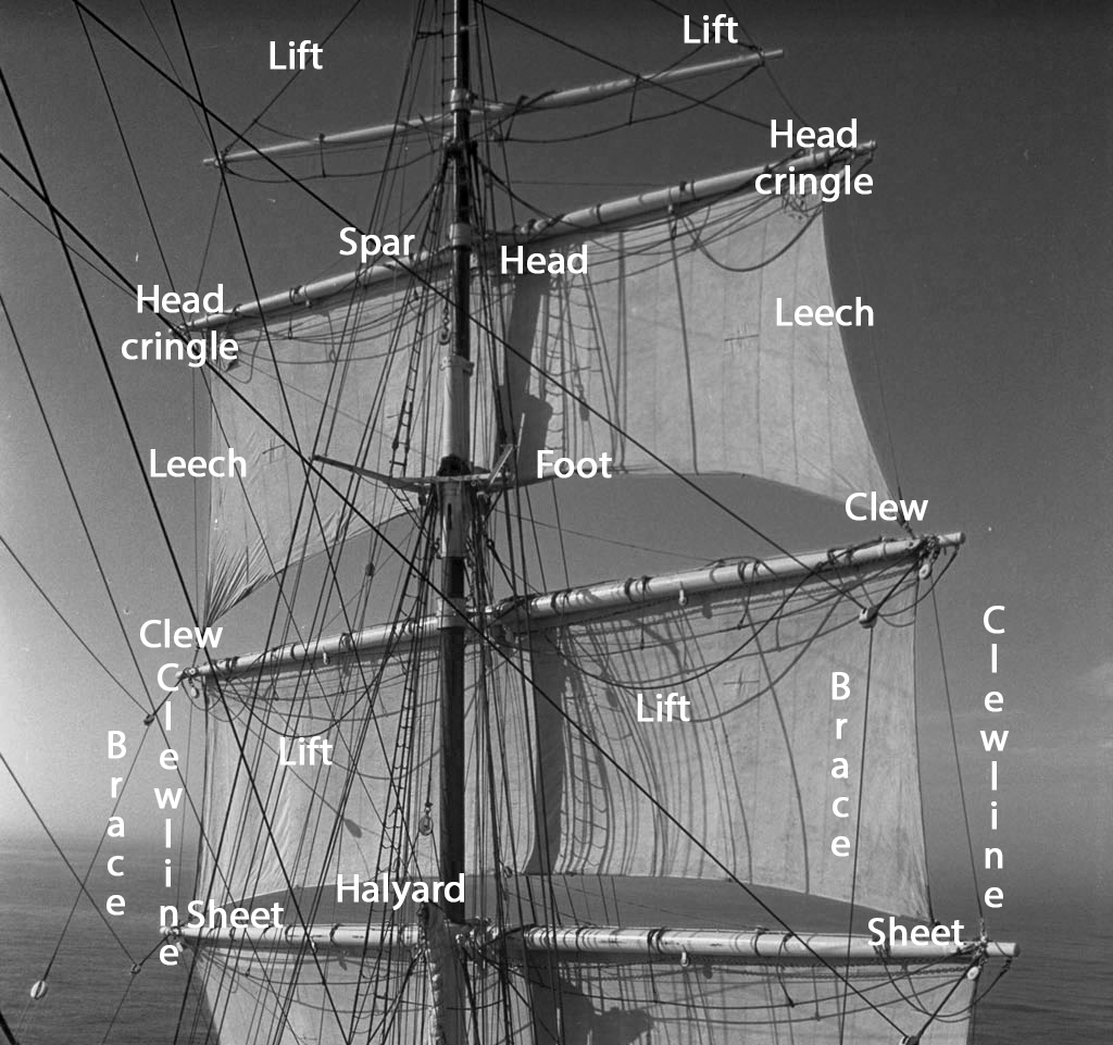
ratlines are generally present on most big rigg ocean going carriers and clippers. Notice them here. Rob
-
I put no faith in the little ones...accomplishing any real work un beknownst to me. Thus far, they have been a dismal disappointment. I've left my Clipper Donald McKay build sitting, clearly exposed, on my work bench...and not one attempt has been made to progress its construction. I even left treats. I'm looking forward to your completion images. Rob
-
She is looking very nice Vlad. What have you considered to do with her when she is complete? build a case..? Put her in a place of honor in your home? Rob
-
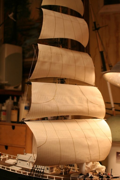
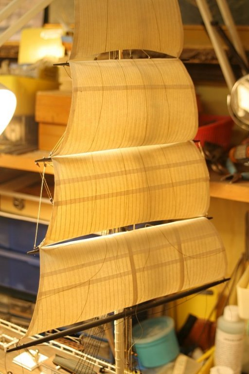
Using the correct tools you can create the *belly* of a sail. I used the steal ball rounding tool...that fondant flowers are made with....a tool used by cake bakers to make cake flowers. Drawn across and rolled, I was able to form the billowing belly of my sails. With paper. Not all the sails are treated this way to provide a natural inconsistency in sail activity. Rob
-
Paper sails have a wonderful translucency to them...and they're very easy to make.... Rob
-
Glory of the Seas is a perfect example of a McKay bow. He used the Naval Hood extensively on all his clippers. The cutwater is the structure below the figurehead and forward the Hood. This design was unique to McKay clippers and was probably his well kept secret. Notice how the figurehead rest nicely and securely on the head of the cutwater and under the Naval Hood. Not simply stuck to the edge of the cutwater...like so many models depict.
-
HMCSS Victoria 1855 by BANYAN - 1:72
rwiederrich replied to BANYAN's topic in - Build logs for subjects built 1851 - 1900
Acid etched stuff is cool...but less like hand crafted....when you are stiving to hand craft details. Reminds me of the printing folks who can design and print what items they need for their models on their 3D printers. I'm impressed with your application of AE...and as usual....you will create stunning realistic structures. More power to ya......Pat. She looks great. Rob- 1,018 replies
-
- 3
-
-
- gun dispatch vessel
- victoria
- (and 2 more)
-
Well Vlad. Several paintings show several different insertion and block points for both the fore topgallant and the fore royal braces. Dependent on her modification year. I think in your case...the fore topgallant inserted and had a downhaul block located at the crosstree base of the topgallant mast on the main, and the royal inserted and downhaul block was located under the main topgallant yard....where the shrouds affixed to the topgallant/royal mast stepping. I inserted and ran both fore topgallant/royal braces back to their downhaul blocks at the main mast topgallant crosstree base. These then ran back and down to their respective purchase blocks on opposite sides of the bulwarks to a return block and then to their pin on the rail. Hope this helps. Rob
-
Yep...the finish line is in sight. By adding all the bunt lines I nearly ran out of fairleads to run them through to the pins. All the fairleads were full. I was afraid I would run out of pins to belay them too. A good working knowledge, led me to know that some pins were doubled up. Is that Beautiful giant...going in a custom case Vlad? Rob
-
Great job George. Great new addition to your collection........😅. I felt a great releasee when I finished Glory of the Seas. I slept like a baby..... What a feeling after years of labor. Rob
- 602 replies
-
- 1
-
-
- Flying Fish
- Model Shipways
- (and 2 more)