JerseyCity Frankie
-
Posts
1,338 -
Joined
-
Last visited
Content Type
Profiles
Forums
Gallery
Events
Everything posted by JerseyCity Frankie
-
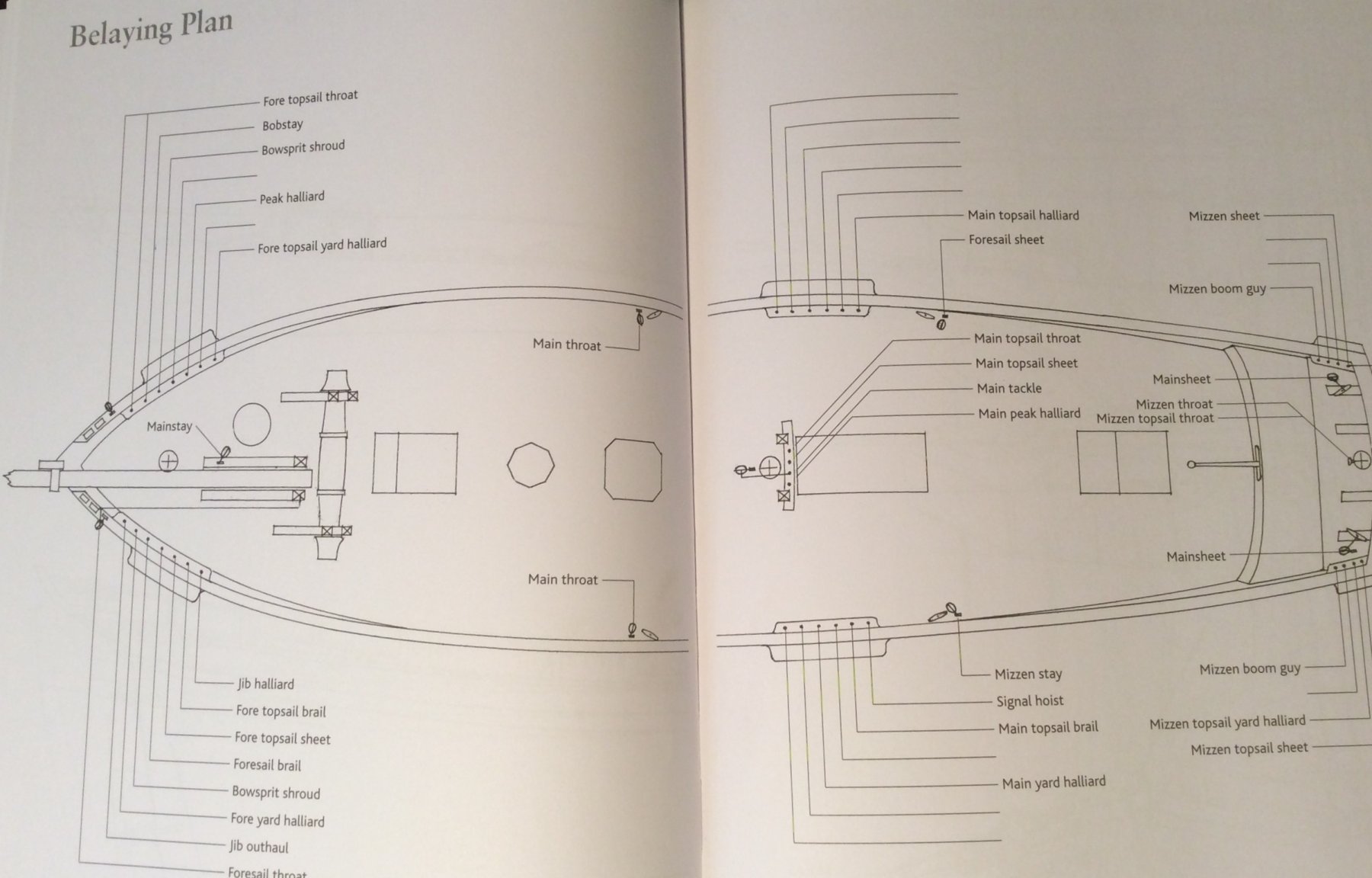
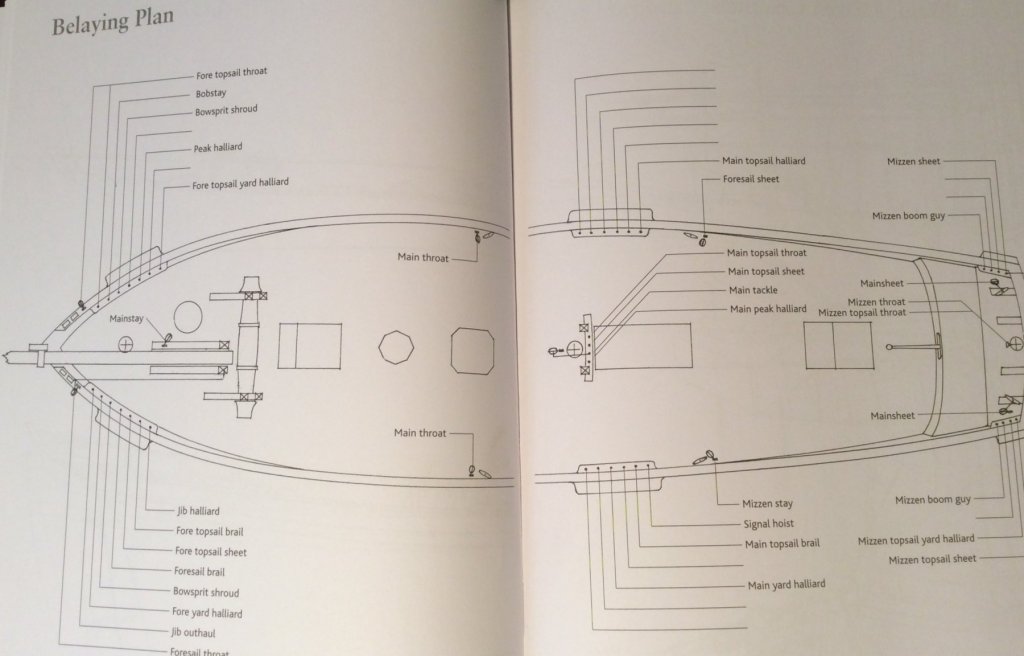
I have a copy of Lennart Petersson's Rigging Fore-And-Aft Craft and I have to say I'm skeptical of a LOT of what he is showing, there is something cringworthy on nearly every page. The book is based entirely on the rigs he found on only three different models. He never tells us which models were used but does say only the French Luger had sails on her. Here is a two page spread showing the "belaying plan" for the lugger on pages 46 and 47. Note that on the Main pinrails he depicts eight pins out of twelve as empty. One of the pins he does show being occupied by a line is used for the signal flag!
-
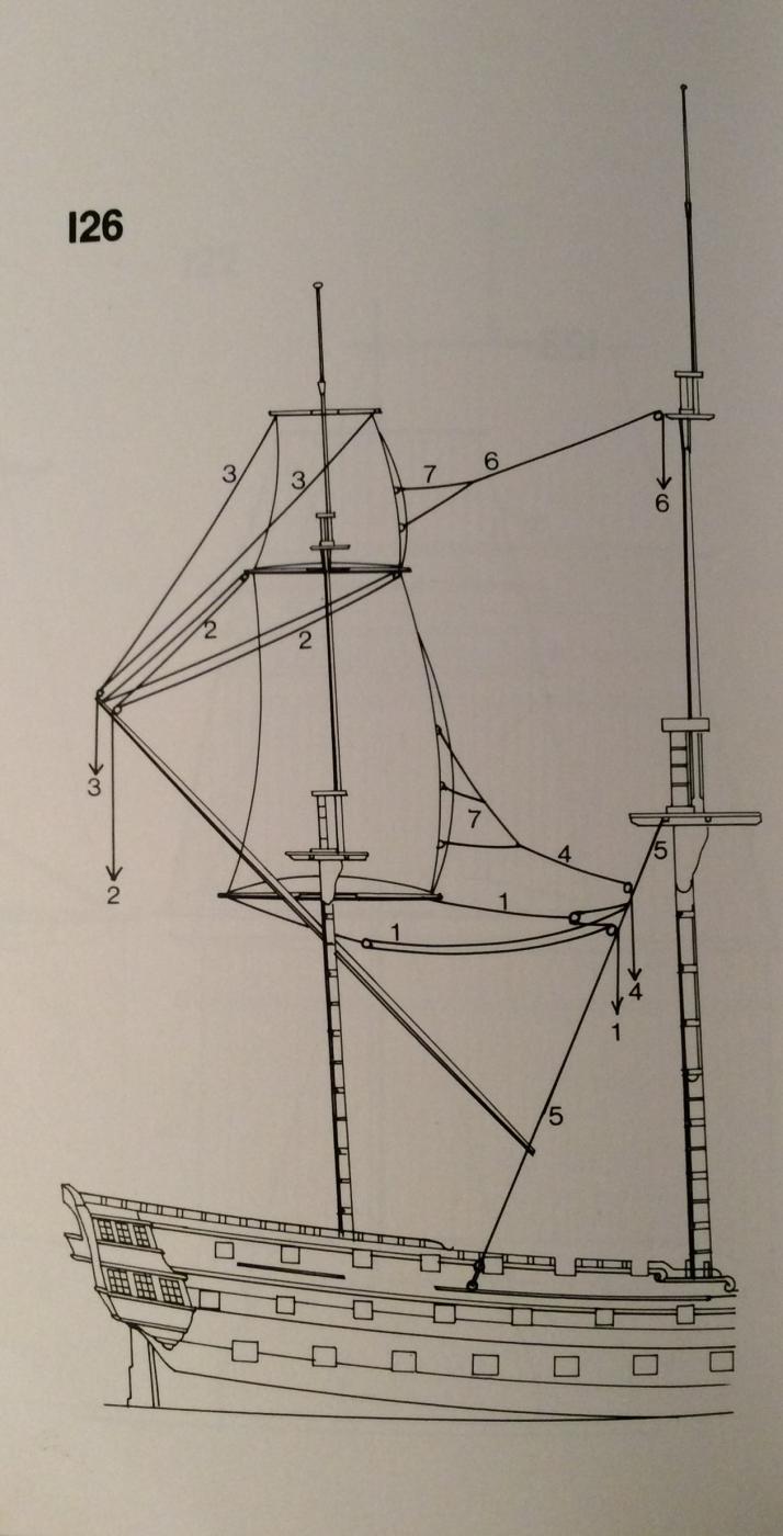
Looking at the diagram from the kit on your build log, the one showing a coast guard ship of the era and it's topsail rig, I was trying to imagine if you could plausibly set the square topsail from the deck. With no ratlines you would not be able to strike and furl that sail aloft, you would have to bring the entire sail and yard back to the deck. Pride of Baltimore does this with her t'gallant but I can't determine if the Pride sail and your ships topsail are of a similar size. To my eye yours looks awfully big to be regularly making the trip into and then back out of the rig. I THINK the idea of running the topmast shrouds down to the deck IS plausible but I wonder why the two topmast shrouds on your model are treated differently and belay in different places down on deck? I think I can recall seeing rigging plans that call for t'gallant shrouds on at least one ship to lead down inside the topmast shrouds to belay in the lower mast tops, so bringing shrouds down further than the foot of their own mast has some plausibility, but I can't say I ever saw topmast shrouds brought to deck level. On the other hand it's hard to find decent information on esoteric schooner rigs in the basic literature.
-
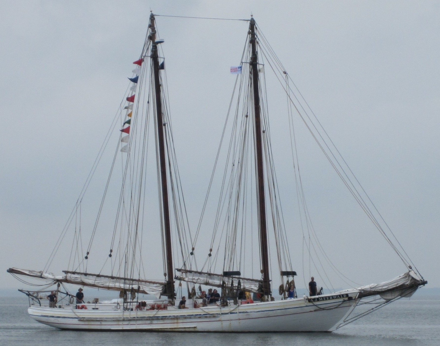
All other considerations aside, my mind balks at the idea of a single shroud on a side for ANY mast. Even today's 24' fiberglass sloops have two shrouds. It's impossible, in my mind, that a rig that tall could survive at sea with so little support. on the subject of ratlines on shrouds, pilot cutters have been known to operate without them. I first heard about this here on MSW and I strongly opined that this was impossible or at least highly unlikely. But I was wrong and the no-ratline practice is well documented. In fact I was astonished later to learn that the schooner A J Merewald to this day has no ratlines!

-
That thing has more the look of a woven mat. I'm not familiar with the period but it strikes me as odd that it tapers down to a single line that encircles the mast. What is the point of the bulk if it's designed in a way that relays on just one part to remain intact? One possible reason for the weaving would be as chafe gear but if that were the case it would be sitting on top of the peril, protecting it, and be replaceable. This IS the peril and damage or chafe on one part would necessitate the swapping out of the entire thing. I view this thing with suspicion.
-
Further clarification, the smaller diameter line that passes back and forth between the deadeyes is known as the Lanyard and I believe it's the line the original question was about. Lanyards are not tarred on pourpose but the shrouds above them are tarred repeatedly over their lifespan. Due to the nature of tar, it can, on a hot day, return to a liquid state and it can flow like syrup. As a result the lanyards WILL become quite tarry over time as the tar from the shrouds drips onto them. my advice is to use line that looks dirty or dark as opposed to bright white.
-
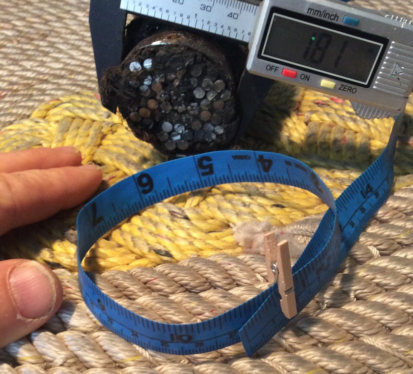
Ten and a half inches is huge! But here is a comparison with a section of steel wire rope that came off the Main Topmast Preventer Stay of the iron ship Wavertree of 1885. The tape circle is ten and a half inches. But consider that the wire rope section is just HALF of the Wavertree Stay, which ran doubled.
- 3,618 replies
-
- 12
-

-
- young america
- clipper
- (and 1 more)
-
? for experienced riggers
JerseyCity Frankie replied to Senior ole salt's topic in Masting, rigging and sails
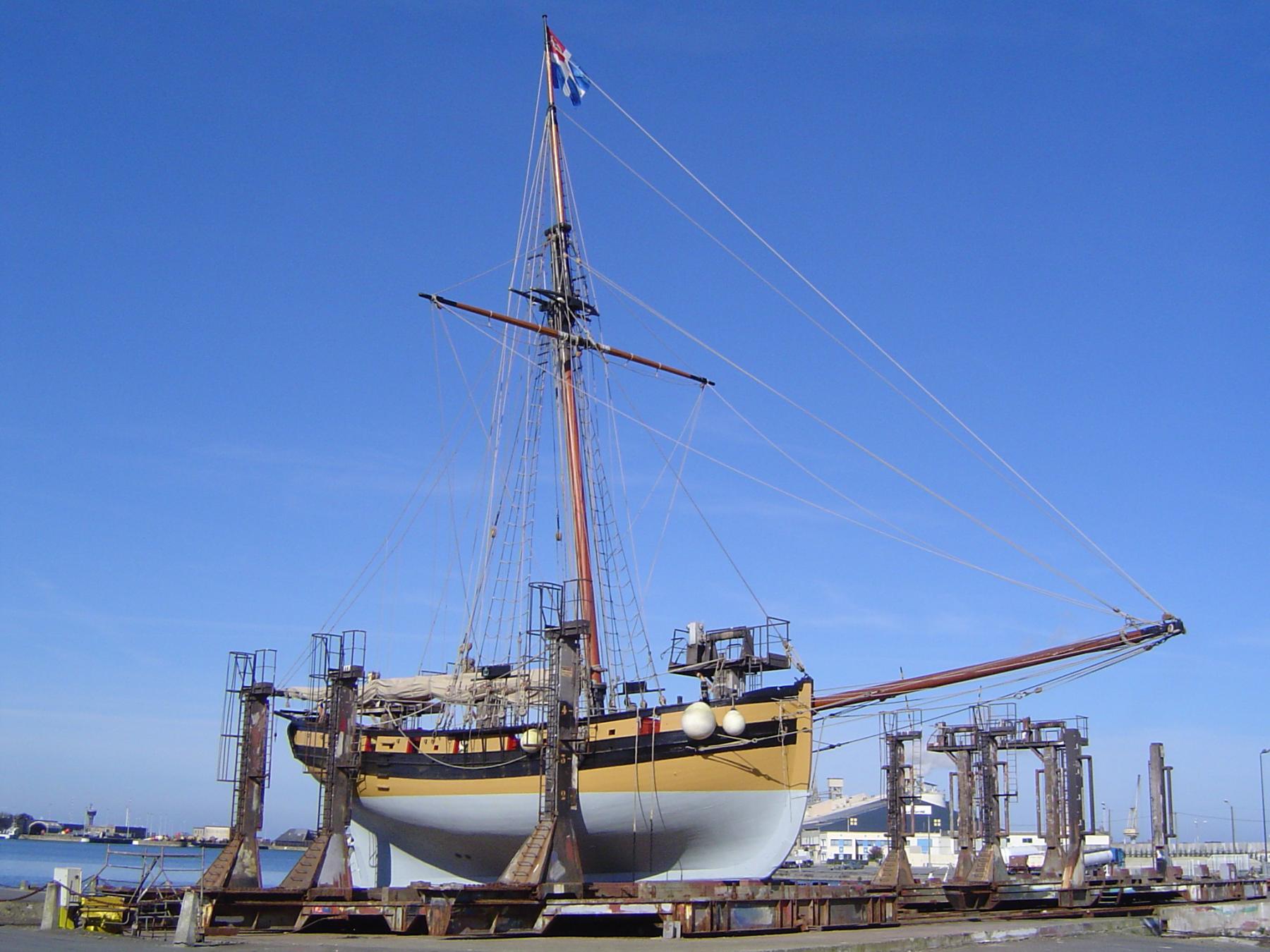
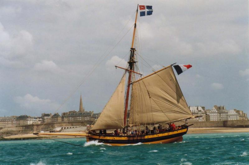
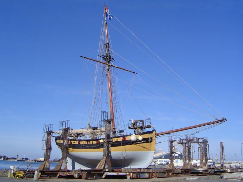
It's hard to find decent images of the rig for the same reason black and white drawings of rigging are often confusing: there is never enough detail to show distinctions. But here are two shots I found of the replica Le Renard that I THINK show the run of the lifts.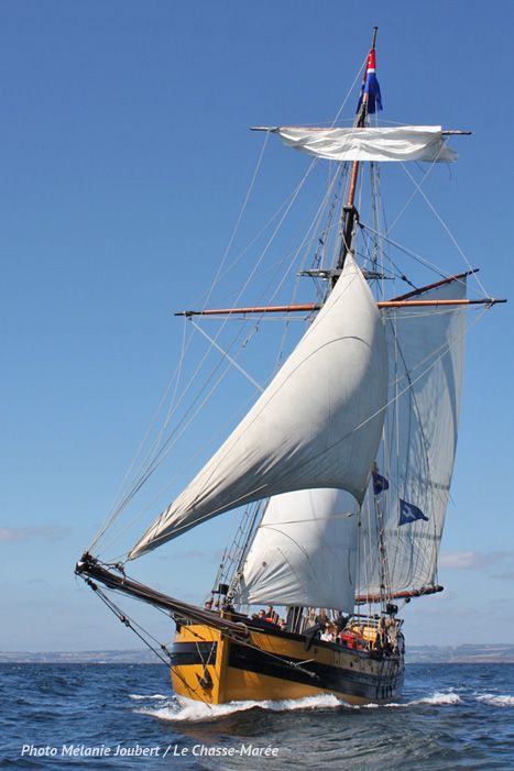
-
? for experienced riggers
JerseyCity Frankie replied to Senior ole salt's topic in Masting, rigging and sails
Gregory I'm going to voice a dissenting opinion on the drawing you've put up from Petterson's book. It's two black lines intersecting and I don't think anyone can say which of the two are stop the other, they are not rendered with enough clarity to be distinctly one way or another. And besides I find that book falls short of the hopes I had for it when I bought a copy, I could go into that elsewhere. And as Chuck has shown, many MANY models depict the lifts going through the shrouds. But these models always have in common the yards braced square, never braced up sharp. But they often ARE in the worlds great collections. It's my opinion they are inaccurately rigged. I could be wrong, I don't have any real world square rigged sailing experience. Speaking of real world experience, it would be good to look at how the lifts are rigged on actual functioning tall ships and tall ship replicas to see how they do it. Again, I could be wrong, but I don't remember ever seeing the lifts going through the shrouds on actual ships with working rigs. -
Lower Mast Crosstree and TrestleTree Snape
JerseyCity Frankie replied to TomShipModel's topic in Masting, rigging and sails
It does seem an odd point to highlight so deliberately. I would have assumed the tapering was simply to reduce unnecessary bulk and windage aloft. But the instructions above are describing a different practice for different crosstrees, suggesting it's not about reducing bulk. I'm trying to come up with a sail handling explanation but why would the configuration differ between fore and Main? Or it could be about providing support for the tops and it's indicating loads in the tops are expected to verry on the fore and Main but I can't imagine why. Even more implausible would be it's a measure taken for the sake of swaying loads Into and out of the Main hatch, to reduce the cross section of the crosstrees most likely to be fouled by rigging used in those operations? But the rim of the top would be the part being contacted, not the crosstrees, and I doubt there would be any line chafing on the underside of the tops.- 1 reply
-
- 1
-
-
- Trestletree
- Crosstree
- (and 1 more)
-
? for experienced riggers
JerseyCity Frankie replied to Senior ole salt's topic in Masting, rigging and sails
Whenever I'm looking at a squar rigged model I check if the builder ran the lifts through the topmast shrouds, they often do. But in fact the lifts have to be forward of the shrouds as shown in your drawing. And yes they would chafe on the shroud. You could compensate by moving the lift blocks on the cap forward as far as they can go. Another option that makes sense to me is to have those blocks on pennants that are long enough to get the running part of the tackle outboard of the shrouds and in this way only the pennants would rub on the shrouds. If you run the lifts through the shrouds you would be making life tough for sailors trying to get aloft on the topmast shrouds while at the same time guaranteeing that both lifts were chaffing all the time. And this arrangement would hamper the function of the truss pendants on the lower yard too. This whole issue of lifts chafing has been glossed over in the literature. For instance Lees doesn't mention it at all. And most ship modelers stick stubbornly to square yards. Hats off to you for thinking outside the box and depicting your yards as they were most often to be seen configured. -
In my opinion I don't think it would be too "wrong" to cut a new stem piece that fits your existing bow area. Purists MAY fault you for altering the profile of the hull, but on the other hand those same purist may be unable to vouch for the accuracy of the boats shape as presented by your kit in the first place. So what I'm suggesting is that you trace the profile of the bow you have made and cut a pice of wood that exactly matches the kit supplied part in all respects accept the yours will be bent at the new angle your boat has now. This way you don't go down the rabbit hole of trying to fix where each and every plank terminates at the bow- you keep all that just as it is. And as a side benefit you will pick up some of the skills that are part of the foundation of wood ship modeling: making parts to fit your model.
-
Attachment of Ratlines to shrouds
JerseyCity Frankie replied to TomShipModel's topic in Masting, rigging and sails
Her Wikipedia page gives her fate as being sunk in Jamaica Bay Long Island. This is on the Atlantic side of Long Island and actually within the Burrough of Queens New York City, not in Long Island Sound. Only nine miles away from where I sit in Jersey City! This proximity makes me want to build her too since it's my home waters and also a place I love, Jamaica Bay is a tidal inlet between Coney Island and Rockaway Beach. Everyone will remember the Ramones song Rockaway Beach! I'm very curious to know now just what the hell she was doing in those very shallow waters. For context, if you motored out of New York harbor and went out to sea under the Varanzano Bridge, then hugged the shore on your left side, heading Easterly, you pass first Coney Island then the mouth of Jamaica Bay, the Rockaway Inlet. -
ROYAL WILLIAM LATEEN YARD
JerseyCity Frankie replied to piratepete007's topic in Masting, rigging and sails
Not shown on the drawing is that the braces will lead down to the deck. You can see there are two pennants with blocks on them attached to the yard, and the hauling part of the two braces each have one end seized to the peak of the gaff and the hauling end of each lead up to and through the blocks on the pennants and back to the peak of the gaf. Not legible in the drawing at that point would be two more blocks or fairleads at the peak of the gaf through which the braces would lead and from there lead down to the deck. It's not uncommon to see mizzen braces led to the peak of the gaff, there is no other good place to afford the necessary leverage to brace yards since the angle straight down to the deck from those yardarms is too steep to provide the leverage to brace but instead that lead pulls almost directly down, not aft.here is a drawing from Anatomy of the Ship Bellona by Brian Lavern showing more detail but I am sure there are better examples out there.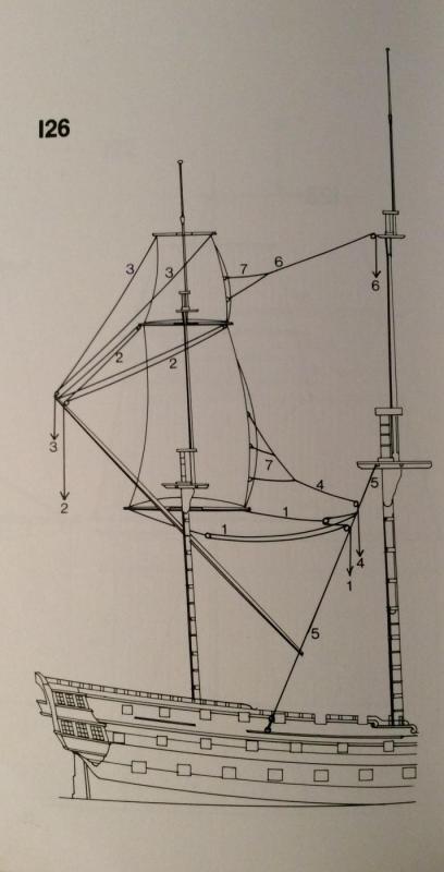
-
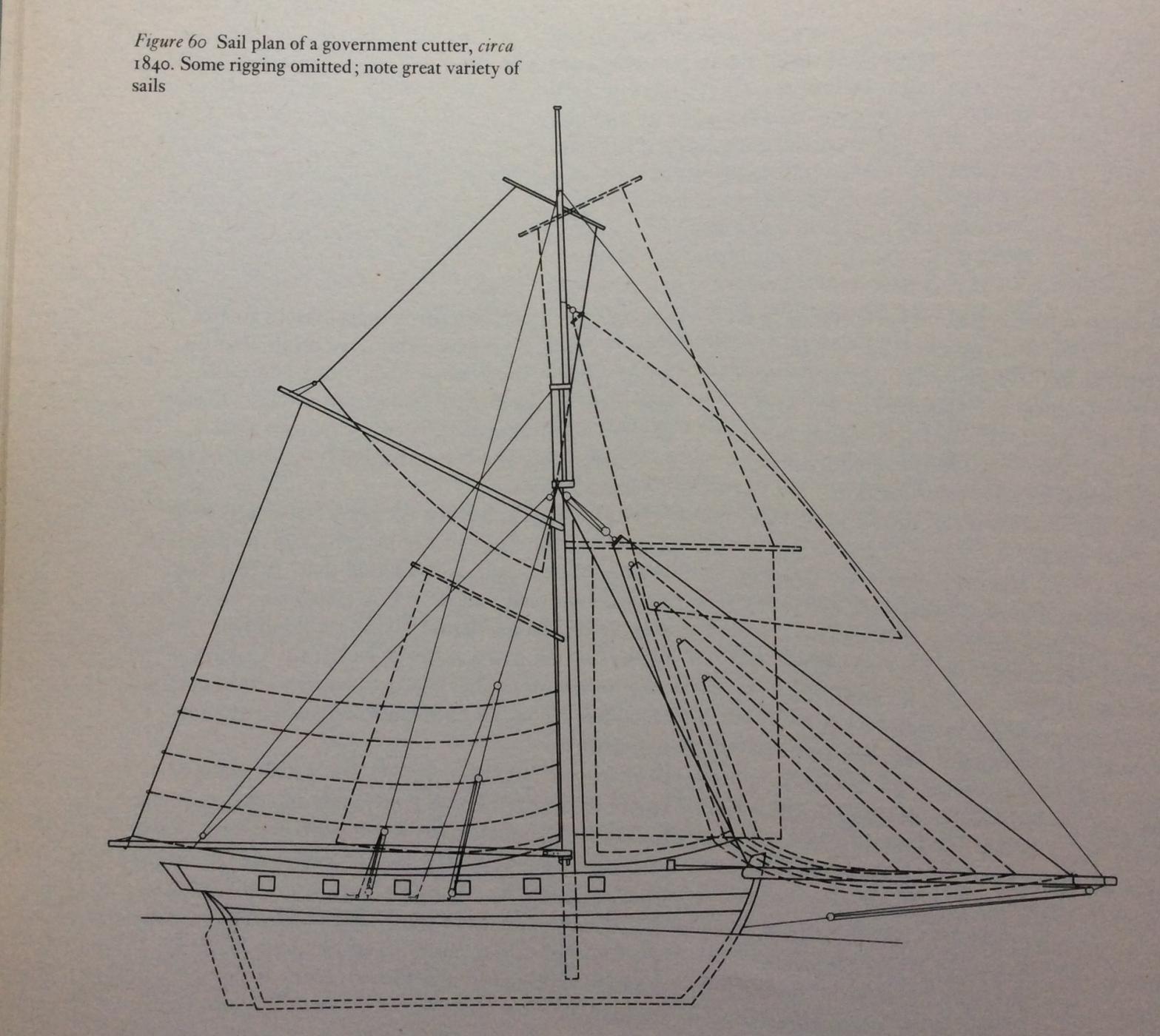
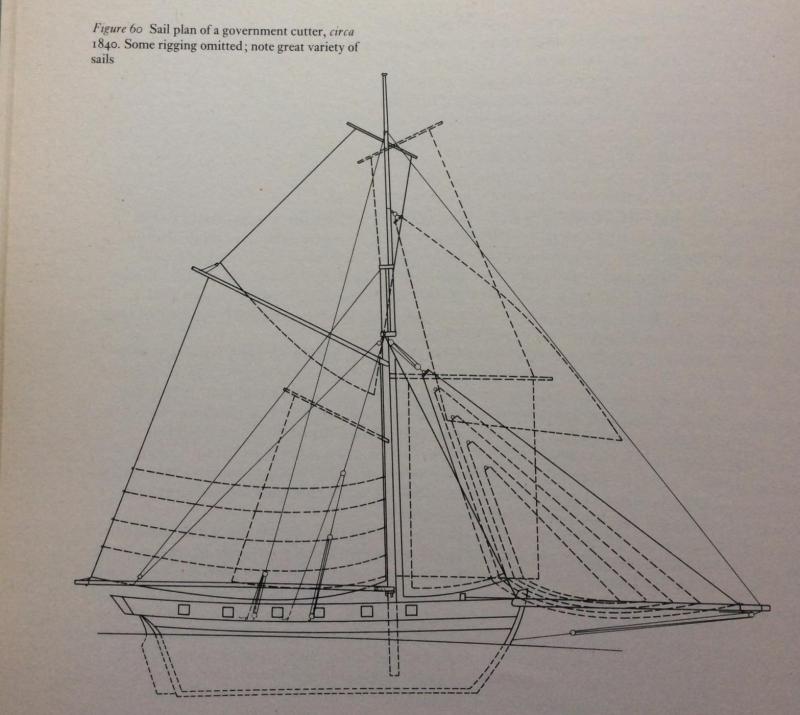
Found this illustration in the book Gaff Rig by John Leather. Shows all potential sails in this cutters inventory. Look at all those headsails!
-
That's my guess. It's true the boom had a traveler on it so they could have adjusted the point at which the tack of the sail met the spar without having to run the spar in or out. When I made my model of Le Reynard I read what I could on the subject but was always full of more questions and I STILL have a lot of questions. It's a VERRY BUSSY bowsprit and very complex, the entire rig must have made tremendous demands on the crews seamanship, I wonder if there are any alive today that could truly put a cutter through its paces? And then imagine when your off watch,what do you do? There's not even room to stand on deck and life below must have been awfull. But it must have been thrilling to sail them in a stiff breeze knowing nobody afloat could lay a hand on you.
-
It's to reduce sail. At its full length, a typical Cutter of the periods bowsprit is rediculously long and a sail is made to fit its length. But you can only get away using that much canvas if the wind isn't too strong or the sea too rough. You are going to outsail everyone else though in light air, because presumably your opponent has a fixed and unchangable head rig that is scaled to an entire range of possible conditions and thus has to be shorter. When it gets rough, you run the bowsprit back inboard and bend on a smaller headsail, one cut to the shorter length you now have. An interesting comparison would be two images of the same Cutter side by side, one with every stitch of canvas set (stunsails, ringtail,etc) and the other completely reefed down. Now that I'm imagining this I would also like to see the figures for the square feet of sail area each configuration represented, the difference would be big.
-
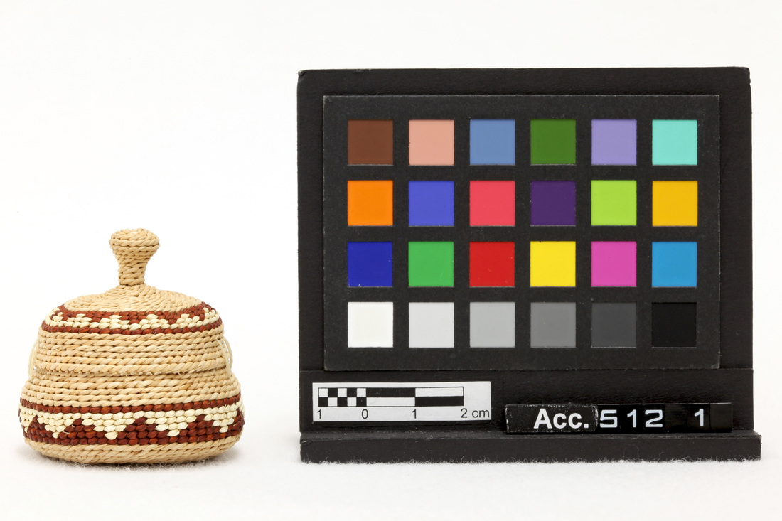
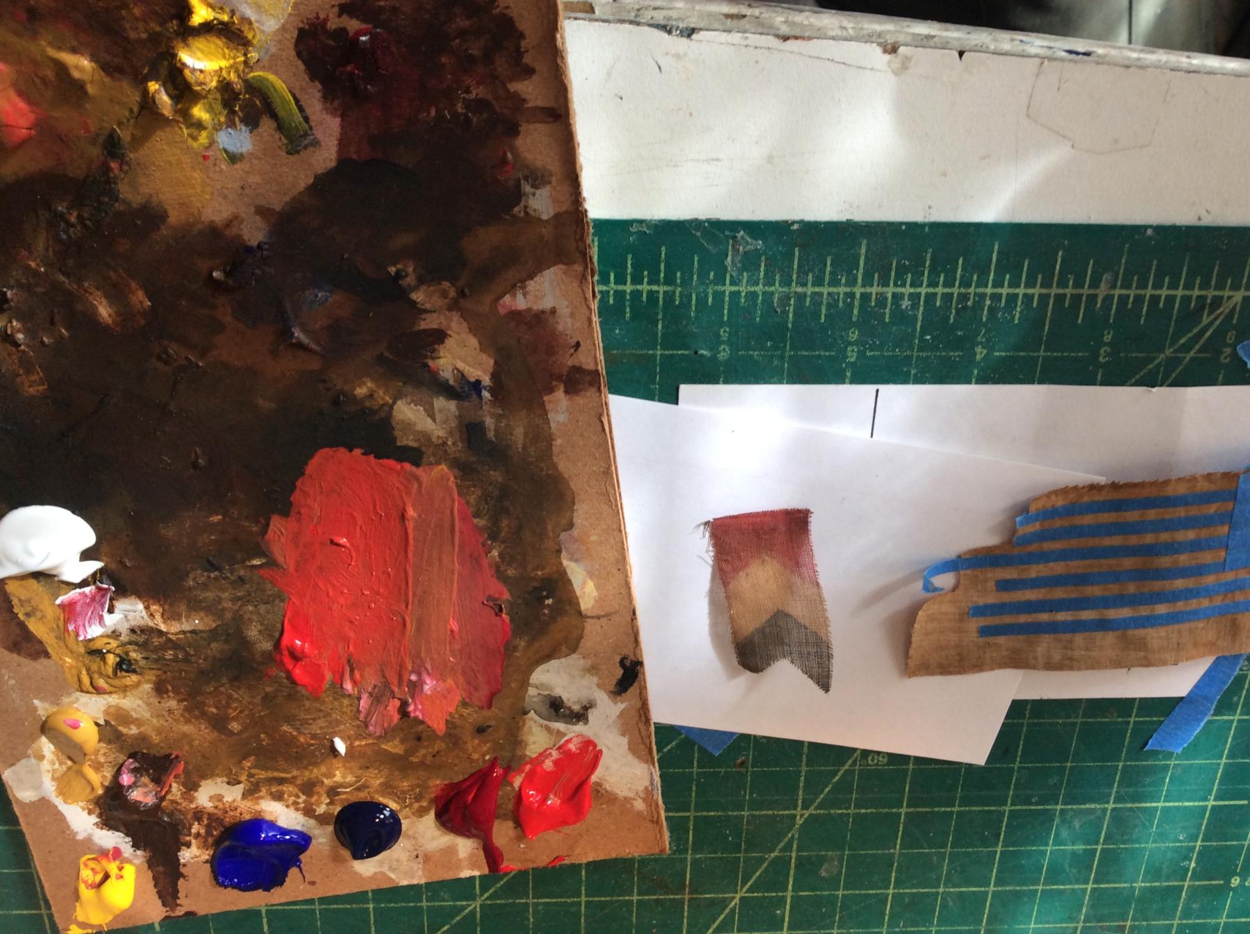
The problem with subtlety in color is that it never translates in photography without being transformed by the camera. Add to that the fact that we are all viewing the image on computer screens from multiple manufacturers, none of us are REALLY seeing the exact same image.thats why museums use a multi colored card placed next to the object they are photographing when they recumbent artifacts with a camera. Wish I knew the name for this sort of card. The idea is that if you yourself have a duplicate card with the same colors on it, you can see instantly if the photography process has altered colors in the subject image. I'm not suggesting everyone acquire one of these cards. But on the other hand I think the inclusion of a small bit of pure white paper included in a photo will alert the viewers eye to the lighting conditions that prevailed when the photo was snapped. If the color of the white paper is slightly blue or grey in the photo, one will know instantly a lot more about all the other colors in the photo.

-
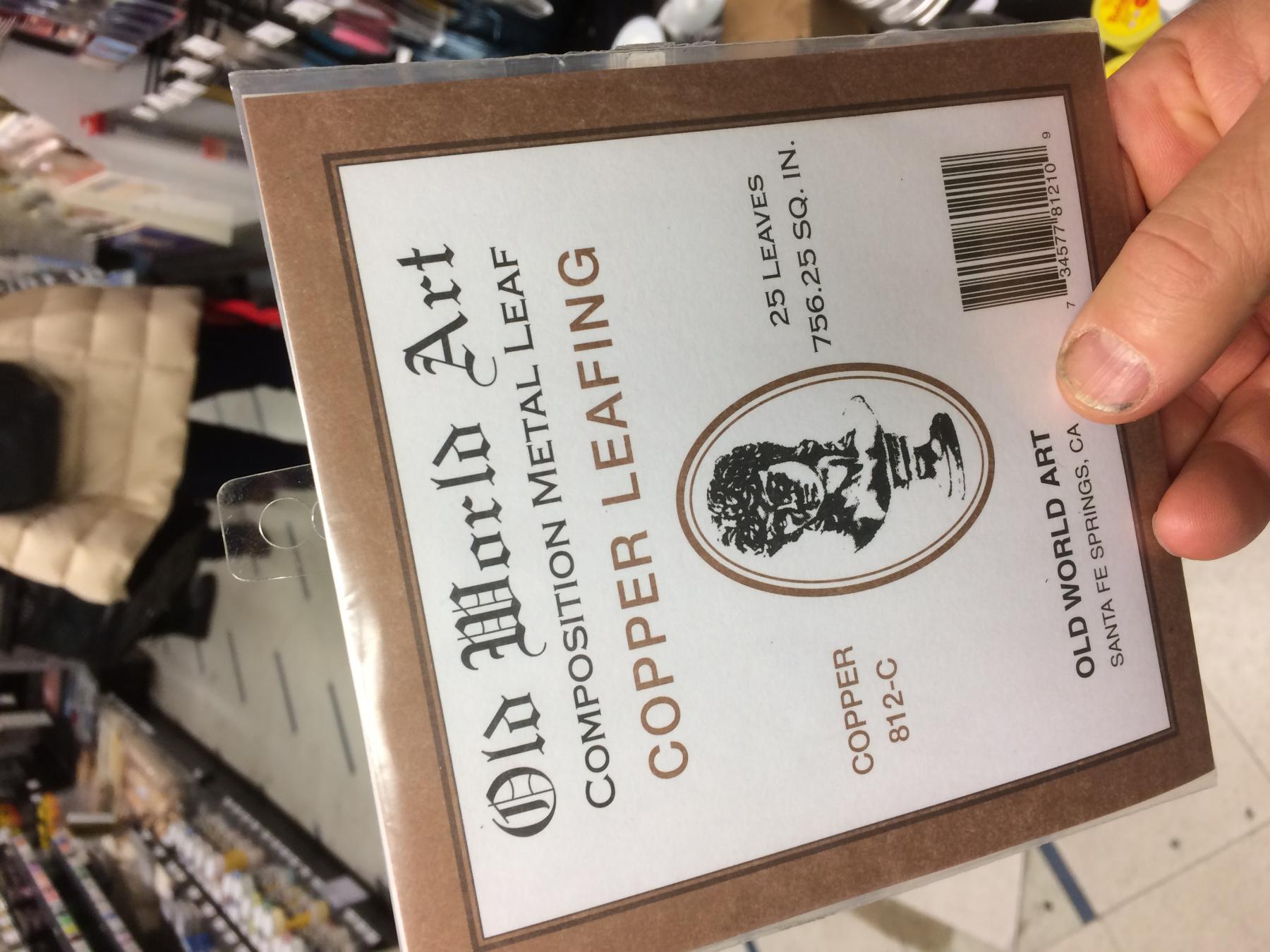
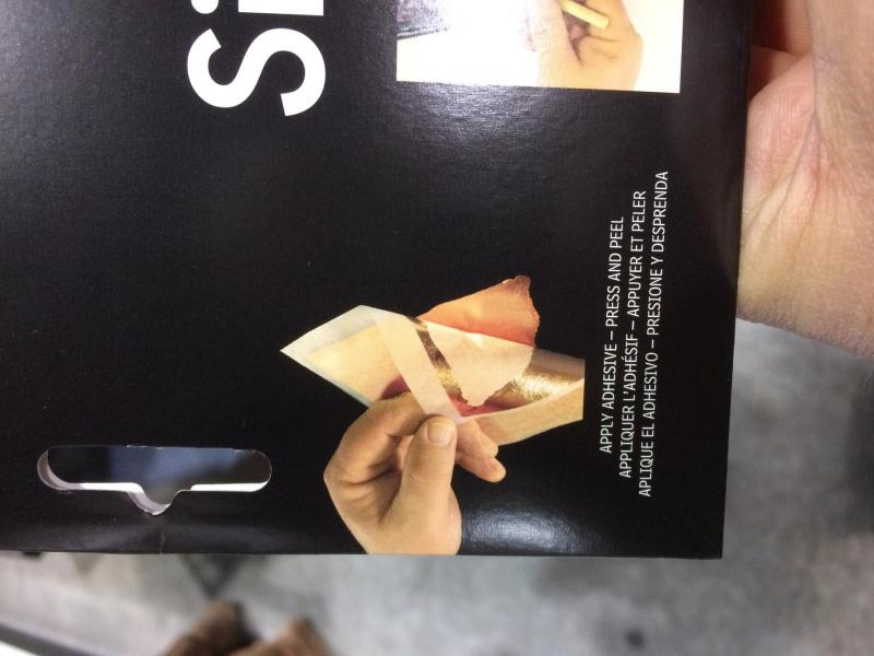
As I suspected, Copper Leaf is an available product. I was at local art supply stores in NYC yesterday and next to the E-Z gold leaf kits I found theses. If you're unfamiliar Gold Leaf is real gold pounded so flat that the 5"square sheets,which come in a deck interleaved with paper, can blow away on a puff of breath and have no internal resiliency. It's the piece of paper it rests on that you can hold in your hand and when it comes time to apply it to a prepared surface the user has to float the leaf off the paper and onto the surface on a puff of air or on the bristles of a paint brush. It's an ancient art form and most gold on antique frames and furniture is gold leaf. The E-Z kits are a dumbed down "do it yourself" product intended for the hobbyist, the REAL gold leaf is kept behind the counter. But reading the package I see that the Copper Leaf IS real copper ( in fact the E-Z"gold"leaf is copper too!) and the two products I found each had twenty paper backed sheets and were priced under $20US. I'm CERTAIN anyone who tried applying this stuff would be facing a steep learning curve. There would be a LOT of surface prep involved. But on the other hand, for the literalist that HAS to have real copper, I think THIS is the thinnest copper you can get.


-
Speaking of hobby paints, I recently went back to Testors model enamel paint for some uses. I last used it in the 1970's and to me it appears completely unchanged. I'm very happy with what it does but there are things it won't do. It does NOT intermix one color to another in the same way I have always been able to intermix colors in all other media I have used over the years -Acrylic Oil and Watercolor. For instance I can't easily mix a range of browns using Testors blue red and yellow, which is child's play in artists mediums. This suggests to me that the base pigment components of the Testors colors are more complex combinations of pigments and this prevents their paint from easily mixing derivative colors as one can with artist paints. So if any of you are vexed when trying to adjust your colors using hobby paint, it isn't YOU, it's the PAINT. I think the hobby paint business is hampered by their need to provide a full range of colors so the user won't be tasked with learning the endlessly subtle art of color mixing. But on the other hand I now feel that that same user is going to be PREVENTED from learning how to mix color if they stick exclusively to hobby paint.
-
It's interesting you bring up how we name colors. In the art world manufacturers of art paints USUALLY name each color by the pigment it's made of and USUALY these paints are made with one predominant pigment. Pigment by the way is the base element emparting the actual color, it's usualy a powder and always selected for its color (naturally) but also for its compatibility with the Binder and it's lightfastness (resistance to UV radiation and fading) and cost. Pigment by itself is NOT paint, it won't stick to a surface unless its mixed with a Binder, it's the binder that makes a paint film stick and resist being scrubbed off.so you can buy Cadmium Red paint (cadmium pigment, a poisonous metallic compound mined from the earth) in Acrylic Oil or Watercolr and it's the Binder that determines what type of paint it is and how it can be thinned or dissolved. Some pigments are not compatible with some binders so you can't get every color in every medium. Alizeren Crimson for instance won't mix with water so you can't buy it in Watercolor or Acrylic (yet recently Windsor Newton figured out a way to make an acrylic version don't ask me how). Hobby paints don't usualy use the names of the pigments in the names of their products and I suspect it's because they are blending many pigments together to achieve their colors. Historical accuracy WILL effect which colors are correct for which period. The science of pigment discovery and use is well documented in the book The Artists Handbook by Ralph Mayer. In it he gives a history of each major pigment and it's clear that only after developments in industry and science have we gained access to most of the colors you see around you in all the coatings everywhere. For instance Prussian Blue was only discovered after chemists began investigating coal tar. So you can't use Prussian Blue on your HMS Victory. Read Oxide has ALWAYS been available though, due to its ease of manufacture and the fact that iron was everywhere. Same with White Lead. Fortunately if you have a copy of Ship Modelers Shop Notes edited by Merritt Edson (and everyone should) you already have a three or four page history of pigments as pertaining to ship models starting on page 140, written by Winthrop Pratt.
-
I was thinking of this topic today as I was mixing some acrylic paint, trying to match colors in flag fabric from an old model I'm restoring. The original flags were likely brighter colors and the fabric would have been white. Now it's brown. Anyway I knew I was NOT going to use pure cadmium red, I had to knock down the intensity of the color or it would jump out at the viewer like a sore thumb. In the photo you can see the cardboard pallet has a lot of browns and tans that I'm mixing into the very bright red. I will call your attention to the big blob of red in the center of the palette, you can see th the right hand side of the blob is muted and duller than the left side, which is more intense. THATS what I was talking about in my post above: mixing some muddy color into the pure color to modulate the intensity. It's still red but now it's less dramatic.

-
I would have assumed that a model would eventually stop giving off gasses as the paint and glue Completed whatever chemical transformation they were undergoing had ceased. say, after a year? I know the corrosion of the lead would continue but that's more a factor of oxygen entering the case, not something escaping. I suppose the wood itself is very slowly drying and that would take decades but I can't imagine the effluvium given off from that would be corrosive? I'm not a chemist though.
-
I wonder why Model Expo is buying back their old kits? Have I got that right? So as not to compete with themselves?
-
Another point I will mention here is scale. Not a surprise to see the word "scale" in a ship model forum right? Believe it or not there is also the concept of "scale color" that gets little attention in my opinion. It's the concept that color loses intensity with distance. The farther away you're eye is from a colored object, the more dull it will appear. This is due to the refraction of the light rays themselves as they pass through the atmosphere. The effect is stronger the greater the distance the light travels through the atmosphere as more and more of the light rays are scattered. If you're building a 1/48 scale model and you are looking at your model three feet away you are 144 SCALE feet away from your model. In order to view your models paint job "in scale" you would have to view it through "scale air", air that was made artificialy denser, full of fog or mist? OR you can duplicate the effect of "atmospheric perspective" (as the concept is known in the Art world) by toning down the colors you apply to the model. In other words you can adulterated your bright red color by adding tiny amounts of complimentary color and/or white paint, just enough to peel back some of the intensity of the Straight-From-the-Bottle Red paint. It's still red, it's just no longer AS red. We are talking about tiny tiny admixtures of color, just enough to get that red slightly less intense. You'r not going for pink. In the case of most colors the diluting color could be a bit of brown. This also goes for the color black on models. I never use black right out of the container unless I'm painting inside a hatch cover trying to fool the eye that there are deep unseen spaces below. Otherwise I use very very dark grey.
-
They are braced. It's tough to find contemporary photos of sailing ships underway and tougher still to find shots like that with some sail furled. All the ones I found in the excellent two volume Medley of Mast and Sail, a Photographic Record (hundreds of period photos) were braced alike with the yards that had canvas set. I found only one photo where it was not the case-see below. Yards braced at different attitudes just look wrong but also if you wanted to brace yards in unalike dispositions some of the running rigging would have to be longer to allow for the disparity between yards you can see in the only example that I could find, the disparity is not that much anyway, it's not representing a very dramatic difference so this one photo isn't an argument in favor of bracing weirdly. Possibly photos exist showing more dramatic differences but that's all I came up with in the two volumes I flipped through just now.