JerseyCity Frankie
-
Posts
1,338 -
Joined
-
Last visited
Content Type
Profiles
Forums
Gallery
Events
Everything posted by JerseyCity Frankie
-
...so if they are not for docklines what other line meets the criteria of being under a lot of strain and thus requiring rollers ( where else on the ship are there rollers for running rigging?) and also needs to have four possible locations to chose from for its lead? And is used so often that a temporary snatch block was dismissed in favor of four permanent fixtures? What comes to my mind, eventually, is the gear on a cable laying ship.You would need rollers if you were paying out miles of line coiled up in the hold. Still not sure you need FOUR rollers though. After even more thought I wonder if the lead is coming in from the side? What if they are related to the boat davits? You could muster a LOT of men on the quarterdeck and lead lines down to them from the Poop with these fairleads, and thus lift any heavy object from the davits. I'm still not convincing myself though.
-
To my eyes the four objects do appear to be fairleads with horizontal rollers at the bottom and a sheave on each side. They are open on the top so the line can be dropped in. I have seen the horizontal rollers Port and Starboard on the edge of the focastle deck on modern ships and they are for heavy lines, like docklines. In this case there are some mysterious aspects. First: Why do you need four of them? Wouldn't one on each side do the trick? Also I imagine a dockline from the 1800's would be similar in diameter to an anchor cable, and these look too small, particularly the side sheaves. And how often are you running a dockline from the stern? And where are you running it to? There is no capstan on deck on Victory.
-
..."Mr Hooper drives the boat, chief!"..... what a great model this is shaping up to be. I mean, I was a fan of the model a few pages back, but now the details are going on and the whole texture of the boat is coming through. This is surely going to be the definitive Orca model.
-
Need Community's Input on Best Kit Manufacturer
JerseyCity Frankie replied to Bandue's topic in Wood ship model kits
The best way to get "community input" is to use a title that says as much as possible about the post. For instance, your post is asking for advice on the best kit manufacturer. If you use "Best Kit Manufacturer" in your title, you will get more people reading your post and likely this will lead to more useful replies. Your title is as vague as possible, nobody will know what the subject is from the title. Think of yourself as a newspaper editor writing a headline.- 10 replies
-
- 4
-

-
- Kits
- model kits
- (and 1 more)
-
Unloading cargo from tall ships
JerseyCity Frankie replied to achuck49's topic in Nautical/Naval History
Many cargo carrying sailing ships did indeed have a dedicated spar for slinging cargo into and out of the hold. Located on the forward side of the main mast and folded vertically stowed parallel to the mast when not in use, hinged on a collar-sometimes sharing the spider band-around the mast at its base- and long enough so that when lowered into position its peak was directly over the main hatch. Vangs on either side controlled its port and starboard motion and conventional tackle lifted and lowered the loads of cargo. This was a slow and messy job, often taking weeks and done by the ships crew, not special cargo handlers. More often than not this took place at anchor, not at a dock, and cargo was discharged into lighters alongside. -
Using a server with dead eyes, standing rigging
JerseyCity Frankie replied to achuck49's topic in Masting, rigging and sails
It sounds like you are planning on serving the shrouds with one continuous thread from end to end? Don't worry about using a singe thread, even in actual practice the serving can go on in multiple pieces- when the serving gets too short you start a new piece of serving and serve over the last bit of the old piece and continue on down the shroud or stay. Also it sounds almost as if you are thinking of the serving as performing the duel function of being the lanyard that tightens the deadeyes? This is NEVER the case. The serving is made of the thinnest thread you can find and is entirely independent of the much thicker line used to lace the upper and lower deadeyes together. This heavier line is called the Lanyard and is only long enough to run through all the holes in the deadeyes with a little left over to make fast the end above the upper deadeye with a few hitches. And to answer your question you lace the lanyard through the deadeyes LAST of all the other operations with attaching the shrouds. In fact its best to NOT glue or in any other way decisively fix the lanyards until you are done rigging the rest of the model- as you rig more on the ship, the lower shrouds often need last minute tension adjustment and only when everything is JUST RIGHT should you put a drop of glue on the Lanyards. -
If the sails on the model are set, this means many ropes had to be used to pull the sails into position. In some cases this can be a lot of line that has to be hauled and now it is just sitting on the deck in a heap. Sailors coil it and hang it so that it is off the deck. The coil will run out without forming knots when the time comes to lower the sail again. Take a Jib, a triangular sail on the bow on something the size of the Cutty Sark. The line that hauls it up will be long enough to raise the sail from near deck level where it lives when the sail is not set, to the point it occupies high over the deck when the sail is set and drawing. All that line is pulled down to the deck and must be coiled so it is out of the way and free to run again when the sail returns to the deck. To add to the complexity, many lines are actually running through two or more blocks to give the needed mechanical advantage, so these lines are longer still since they also have to run through the blocks, in many cases three or four times, which makes them three or four times longer than if it was just a single line. So every pin on the ship will have a coil on it at one point or another, and some of the coils are big and some of them are smaller, depending on the job the line is doing and how much line has to move to complete the task its doing. But what if you are showing the model with the sails down or off? If the sail is down or furled or whatever, you still need the working end of the line to be long enough for many people to grab onto it and pull on it, to haul the sail into position when the time comes. If its a large bit of the rig, like the Topsail Yard, you will need all the available crew to lift the heavy load, picture fifteen or twenty guys stretched in a line all getting ready to haul on this line. So this line needs to have at least enough extra on the end to allow twenty people to get a hand on it, and this bit will have to be coiled and hung on the pin too.
-
Have just discovered your log for the Arethusa. Its magnificent! I I am not sure I have ever seen better deck fittings, and yes I know this is a strong statement. But put it this way: If I never see better deck fittings on models I will NOT feel cheated. I think a lot of builders take schooners as being some sort of lesser class of subject matter and often you see simplifications in details and rigging on schooner models, as if the bar was low for schooners. So I am very pleased to see the lengths you are going to to do the subject proper justice. Yah Thalo Blue is a very very strong pigment! Why not ultramarine or cobalt? I can't think of ANY other color with the power to alter the final color mixture with such a tiny portion of itself in the mix, no other pigment I know of is as strong.
-
11 1/2" Standing rigging all the way up to the tgallent level? Thats some mighty thick line! Must have been a bear to manhandle that line back in the day when they were rigging. Just getting a backstay that long aboard and on deck in the right spot must have been a challenge. Then to raise it into the rigging that high? Crazy.
-
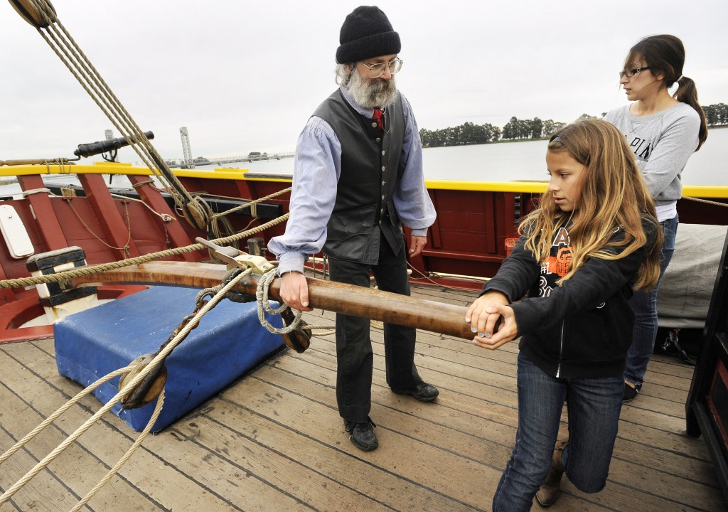
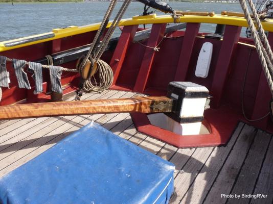
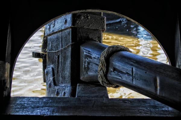
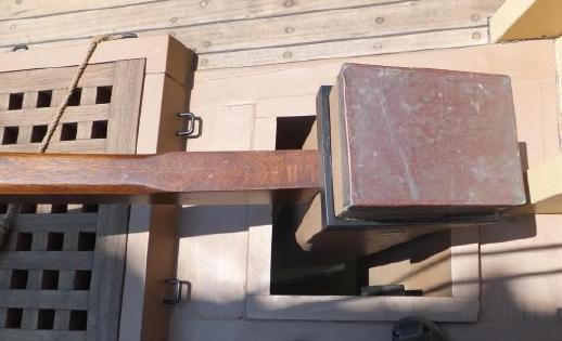
Found some tiller images on the web. I find it helpful to look at actual examples of gear in cases like this. Even though these are modern replicas, you can see these are wooden rudder heads and tillers, and the forces involved are the same as would be found at any time in history. Clear in these examples are iron reinforcings and they come as no surprise.


-
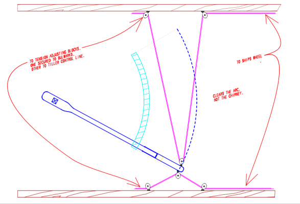
I am puzzled by the destination marked "To Tension Adjusting Blocks" in the notation on this drawing. Is it being suggested that even more tackle is needed for these lines? I think this rig is already too complex. Not shown in the drawing are the forward lead blocks to guide the line back to the drum on the wheel, six blocks on the bulwarks and two on the tiller in total, plus "tension adjusting blocks" somewhere aft? There is not-in my opinion- a need for all the blocks indicated and hinted at in the drawing to do the job of transferring forces from the wheel to the tiller. Here is how I would rig it: The line end of the line is fixed to the aftermost leadblock on the bullwarks and is rove through the block on the extreme end of the tiller then rove through the aftermost lead block it originated from. It then is lead forward to another bulwark mounted leadblock located exactly abreast the drum on the wheel. It takes the prescribed number of turns around the wheel then repeats the lead on the opposite bulwark. There are six blocks in total. Without building a working model its unlikely you are going to see how much actual slack is introduced into the line by the arc the head of the tiller passes through. But lets examine this arc. Lets assume for the sake of argument that when the rudder is amidships the head of the tiller is two feet above an imaginary port and starboard line drawn on a flat deck with no curve built into it ( I know our deck has a curve but lets keep it simple). Now lets assume that when the tiller is hard over the height above the imaginary athwartship line has been reduced by a foot (and this is being generous). All one need do is mount the lead block on the bulwark at a point equidistant between these two heights at the 1.5' level and half the slack is eliminated. With three or more turns on the drum at the wheel this amount of slack can be easily dealt with if there is ever a point where the tension falls below the level of keeping the turns tight. Simply "tailing" the slack on the opposite side of the drum would keep all tension required to ensure the turns were holding. Also selecting a line with a lot of elasticity will go a long way to keep the slack manageable.
-
Beginning to Do Some Seizing
JerseyCity Frankie replied to mikiek's topic in Masting, rigging and sails
An avenue of investigation is to look at how things are done on contemporary restoration and replica ships- with a caution! No two restoration or replica ships have the same degree of accuracy and fidelity and its very easy to find anachronistic methods and gear on "accurate" ships. But there are some vessels that have onboard practices methods materials and equipment that are more accurate than others. The first that comes to mind is the French frigate Hermione. EVERYTHING on that ship is period accurate and its unlikely any future ships will match her attention to historical accuracy in materials- her rigging and sails are entirely natural fiber. The HMB Endeavoure and the Brig Niagara and the schooner Pride of Baltimore II should also be trusted to portray accurate period details and I may be wrong but I believe they too use natural fiber rigging, or have in the past. -
Wow this model is looking great! Have you read the Patric O'Brien novels that feature the Leopard? In the novel Desolation Island She fights a battle down int he roaring forties with a vindictive Dutch ship and the author presents the whole episode very dramatically.
-
Cabbie thats a great bunch of photos on that website you linked to. I'm taking the liberty of cutting and pasting the relevant shot of the tiller. Also the HMB Endeavour replica has a facebook page which has a very large number of photos taken over many years and I found some tiler photos there too. In these photos I see a wooden tiller with iron features bolted to each end. In some of the photos the wood is revealed to be laminated of several pieces, which makes perfect sense for such a crucial part of the ship. The initial mystery of "what is this arc shaped object on this drawing" is no closer to being solved though. Again I wonder if any tiller on any exposed deck on any ship or model has ever exhibited such an arc shaped object? I have never seen one.


-
Beginning to Do Some Seizing
JerseyCity Frankie replied to mikiek's topic in Masting, rigging and sails
An excellent question and an issue that is often one of my pet peeves about ship models. Too often the stuff used for seizings on models is grossly out of scale and draws attention to itself by taking up too much space, by appearing way too fat and bulky. Seizings and serving stuff and any kind of binding or lashing put onto a larger line are always made with small stuff considerably smaller than the line they are used on. You will never see something like a 2" thick line wrapped with something as large as a 1" line on an actual ship. Here is an example I pulled off the web with seizing stuff way too large and drawing attention to itself.The line marked #1 in the photo looks more like a giant sleeve. In reality it would blend into the contour of the line it was clapped onto. The stuff used in the photo on #1 looks as thick as one of the three strands of the lines it has been put onto, and this is way too thick. The line used in #2 is better. Aesthetically I like the seizings to be a slightly lighter or darker color of the line it is on, just so it is visible, since if done with stuff of a realistic size it tends to visually disappear otherwise.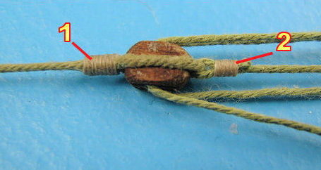
-
Here is a shot from the link provided above of the replica. By all accounts a VERY faithful replica. By my reckoning the portion of the tiller cantilevered from the Rudder Head is about 15'and that IS a lot of wood with presumably a very strong levering force constantly stressing the Rudder Head. But it appears to be fine in the photo. Also I have never seen any sort of arc shaped structure above decks associated with any tiller on any ship or model that I can recall. Its true that large ships with rudders set under an upper deck do have an arc shaped shelf the tiller hangs from, but in this case the tiller HANGS from it. The conjectural structure above deck would be below the tiller and then what is it doing for you? A wooden truck or roller would do the same job and I will say I have never seen provision for any such roller or guide of any kind on ships that I can remember. Maybe I am wrong. What I can NOT imagine is a guide or Tiller Sweep set ABOVE a tiller on an exposed deck, that is just too much stuff getting in the way of everything on the crowded small space aft. But the drawing is clearly showing a Tiller Sweep and this is a mystery. To me it suggests evidence the tiller was relocated to the underside of the deck and then it could have a Tiller Sweep that would be useful.

-
Jewelers Saw
JerseyCity Frankie replied to Roger Pellett's topic in Modeling tools and Workshop Equipment
My advice is to buy an inexpensive one on ebay and use and abuse it. You will break a lot of blades but you will learn what you like or don't like and you won't be out a lot of money. Here is one at a great store I frequent in New York CIty, they are asking $16.00 : http://www.zakjewelrytools.com/collections/sawframes-blades/products/jewelers-sawframe-with-end-screw -
Rigging tools how are they used
JerseyCity Frankie replied to Telp's topic in Modeling tools and Workshop Equipment
I think tools like this make more sense to the tool merchandising people than they do to actual model builders. As a product, they have the appeal of being easy to manufacture and ship and they appear practical. From the standpoint of a model builder they do not bring much to the table when it comes to implementation. Molded handles don't add functionality in a case like this and limit, to some extent, where the tool can be menouvered. A spool of stout wire, which can maybe be found in the same price range, will provide the model builder with a lot more functionality over many more model building applications. Easily cut and bent to the desired length and shape, no store bought tool will match the adaptability of simple thick bendable wire. In actual use, I am using the wire to get lines onto fife rails my thick fingers cant reach through the shrouds and stays. A straight tool will not be as useful as a wire I can bend an elbow into in order to customize it to get around the whatsit that is blocking access to the pin I am trying to belay to. -
I am sure you have heard of the biggest and newest and perhaps the most carefully executed viking ship replica, the Dragon Herald? If not, google "Dragon Herald" http://www.drakenexpeditionamerica.com/ I have been following their progress on social media and they have done a lot of research and implementation of rigging in the last two years. Google them. Also spelled DRAKEN HARALD HÅRFAGRE
-
Attaching a Cutter's foresail to its horse rail
JerseyCity Frankie replied to tkay11's topic in Masting, rigging and sails
The whole idea of the Horse is to make the entire sail self tending. The vessel can go about tack upon tack and the sheet and its rigging move by themselves across the Horse as the vessel moves through the eye of the wind, nobody has to lay a hand on it but it is ONLY self tending if the sheet stays the same length as it moves across the horse. If you have the tail of your tackle coming right off the blocks on the sail or from the Horse to a point of belay on any other fixed position on deck (unless it is dead midships), the lines length changes as the block on the horse moves athwartship and now you need crew tending the sheet every time you tack- they will need to take up on the line and ease it out again as the block on the horse moves across. Steel avoids this problem by having the sheet belay to itself- via those frapping turns. If you want to belay the sheet anywhere else its best to chose a point amidships so the rig will remain symmetrical Port and Starboard, or have a lead block fixed to the deck amidships to do the same thing. But this still allows a LOT of slcak in the line as the block on the horse moves across the deck and things can get pretty wild in the eye of the wind, the block shooting back and forth violently as the sail luffs, and now all that slack line is going to foul on things, at JUST the point you do not want it to, guaranteed. The sheet on the club footed staysail on the schooner Pioneer is on a horse. There are two single blocks on the club of the staysail about four feet apart from each other and there is a double block on the horse. This block rides on a large shackle but a thimble would work too.The line starts on the bail of the double block on the horse and is rove back and forth to the two blocks on the club and the two sheeves on the double block , then it goes to another single block at the MASTHEAD and thus down to the pinrail. Running the line via the masthead avoids the problem of slack forming in the sheet every time it moves across the traveler and this makes it more eficient. It also means there is no line running across the deck at ankle height in the crowded deckspace forward. Steel appears to belay the sheet to itself- those frapping turns. This makes perfect sense but makes it a bit more difficult to tend than a line on a pin would be. You do still need to adjust the sheet for different points of sail, but when tacking you can let the sail tack itself with no adjustments to the sheet needed at all. -
I would like to see some research on the history of bottom or antifouling paint. I am building a late 1800's yacht and taking a total guess on what the bottom paint is. I went with a red oxide color. But it makes me wonder about the history and the timeline of availability of specialized bottom paint. At some point in the past the green color of copper based coatings would have come in, but at what point did the commercial paint industry mature to the point where it could market such specialty paints to the boating world? And before the iron oxide paint, were they all just using "White Stuff"? Tallow and grease and concoctions of tar? The vessel I am building is under 40' and I can not imagine the owners having the wherewithal to copper. But copper was certainly still in the greater picture in the second half of the nineteenth century, if on the way out.
-
Size of blocks & rigging thickness ?
JerseyCity Frankie replied to Senior ole salt's topic in Masting, rigging and sails
In this video you can see why it is necessary to slush the mast with grease! There was some difficulty with the mast hoops binding both in raising and lowering the Main. Regarding the sizes of rigging and blocks on your model: you can see most of the running rigging in the video. Providence, than as now, is a small vessel and the forces involved in the rig are not as strong as on larger ships with heavier gear and more canvas. In the video, near the end, you can see them hauling in the Main Sheet. You can also see them raising then lowering the Main at the beginning at end of the video. The halyards and the sheet would likely be about the same diameter AND , being on the Mainsail, they would represent the thickest running rigging you will find anywhere on the vessel. As you can see in the video the line is not very thick. The thickest line visible in the video is a pair of docklines coiled and hung up in the bows. (its odd to see dockline hung, usually it is coiled on deck). This line looks to me like it is about 2.5" diameter at most, but keep in mind it is modern braided line and an actual stranded hempen hawser from back in the day would be thicker, maybe 4"? The sheet and the hailyard look to my eye to be about an inch or an inch and a half. -
The color of the sails is perfect! They are very convincing "working boat" sails. Too often people use bright white for the sails and it gives the model an unearthly appearance. Also I am always saddened a little when I see a completed schooner or other for-and-aft vessel and they decided to leave the sails off. All that lovely space above the deck looks so cold and empty without the beautiful canvas filling the negative space. Your model looks great and I cant wait to see what you will build next. Congratulations.
-
As a practical matter, the horse need not be any higher off the deck than the becket of the sheetblock attached to it would need to clear the deck. But there are some considerations about having it too low- with the limited deckspace on a cutter you may need on occasion to tuck a coil under the horse, you certainly don't want a line laying across it. The training tackle for the guns for instance. The horse I have seen on actual schooners is a foot off the deck, with a curve that matches the deck's camber. A factor to govern the width of the horse, and maybe an argument in favor of putting it atop the bullwarks after all, is the height of the bullwarks and the hammock netting and its irons above that: There is no point in getting the sheet so far outboard that the lead of the line would foul these parts of the vessel when the sail is sheeted out.
-
What company is doing the Brig Mercury kit?