


JerseyCity Frankie
-
Posts
1,338 -
Joined
-
Last visited
Reputation Activity
-
 JerseyCity Frankie reacted to Bill Jackson in Real Ships or Furniture?
You know, I have read the same thing about colors. That was one of the first things I did, was to research the correct colors. I even emailed Portugal, where the galleon was built in 1579. Neither the main libraries nor the museum had any info.
So I emailed the company who made the model. Again, they have no idea what the real colors were. But on the box it was all painted and really looked good...?????
Since I live in the Philippines, and the galleon I am building was one of the "Manila Galleons" that was not built here but repaired a number of times along with 108 other galleons, I will go to the city where the shipyard was (back in the day) and see what I can find.
Thanks for you words and I have learned alot from this forum..
Bill
-
 JerseyCity Frankie got a reaction from Tom E in US Brig Niagara by Tom E - Model Shipways - 1:64 Scale
I found shaping the tagalants very trying. I forget how many I made but more than two! I’d either make them wrong or break them while trying to taper them. It’s one of those things where I wonder if it wouldn’t be easier doing it full scale. Particularly at the very top of the mast, shaving it thinner and thinner and saying to myself “this is where it will break one day if it’s too thin”.
-
JerseyCity Frankie reacted to Tom E in US Brig Niagara by Tom E - Model Shipways - 1:64 Scale
Evening,
On the couch, cold drink on the end table, Red Sox playing the Yankees at Fenway on the tube.
Thought I'd share an update.
Gary,
I took a look at the tip you gave. Your right, It's a few steps before I get there, but I see what you mean.
With the wire it should give the piece some "backbone" and limit the twist.
I should be starting Yards soon.
I started the Main TG/Royal Mast.
I start by marking off certain features then start shaping.
If you look at the plans, I mark the date of when I started a certain piece.
Don't know why, Just do.
But, Sadly, It's taken a year from when I started the Fore TG/Royal to when I started the Main TG/Royal.
Little bit of a snails pace here!!!!
Oh well, no rush.
Generally start to cut in certain features, then continue to slowly shape/sand.
Having no belt sander, lathe, or the like, It's all by hand.
Always checking the fit with the Main Top Mast.
She's still a bit rough, but will slowly smooth out into its final shape.
I now have a full compliment of masts!
Little bit of a milestone in my head.
The board for the masts should prove invaluable when I start rigging.
Thanks for watching!
Tom E
-
JerseyCity Frankie reacted to rwiederrich in Great Republic 1853 by rwiederrich - FINISHED - four masted extreme clipper
Next are a bunch of pics I took of the sail mounted with the lifts and downhauls run along with their blocks.
Rob
-
 JerseyCity Frankie got a reaction from J11 in Fair American by abelson - FINISHED - Model Shipways - Scale 1:48 - second wooden ship build
Brady’s Kedge-Anchor has details about rigging footropes on the jibboom: https://books.google.com/books?id=YihFAAAAYAAJ&printsec=frontcover&dq=kedge-anchor&hl=en&sa=X&ved=0ahUKEwiQpvHC27jkAhWIiOAKHZ9IBw0Q6AEIJzAA#v=onepage&q=kedge-anchor&f=false
-
JerseyCity Frankie reacted to jdbondy in Pride of Baltimore II by jdbondy - FINISHED - Model Shipways - 1:64 scale
So at this point it is the fall of 2016 and we are within 2 years (!) of finishing the model. What remains is installation of the masts and associated sails and spars, then sorting out the rigging. Which, I might add, is my favorite part of building ship models. I love sorting out all the lines and bringing everything to manageable order, just like the sailors who actually sail these ships have to do in reality.
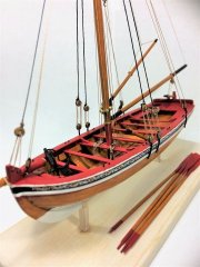
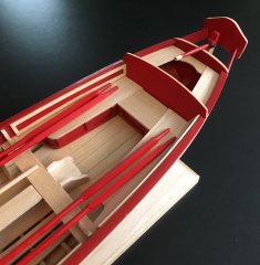
But first, I went ahead and installed the ships boat, Chasseur, which was finished many years ago as I began to ramp back up my ship modeling efforts. I did have to take out all the spars and oars, and give it a good dusting. Two lines secure the boat to its cradle; I did not have much to go on in terms of how this line was rigged, but I think in the end that it looks reasonable.
These are the brail blocks that are installed on several of the mast hoops for the foremast. The model will display a furled foresail, pulled up against the gaff and the foremast. These very small blocks (3 mm blocks as I recall, a little smaller than a 3/32” block) had to be carefully rigged so their seizing wouldn’t come apart under tension.
Here I am bending the foresail to the fore gaff. The fore gaff remains in its rigged position when the boat is docked; it does not come down. The shape of the sail had to be cut so that when I furled it up against the gaff, it would flake neatly against it without too much bulk. The same was true for the part of the sail that would be furled against the foremast.
A running stitch was used to rig the sail to the gaff. Before bending the sail to the gaff, I picked the points where the line would travel through the sail and marked them with pencil points. I then opened them with a needle, then applied some of the anti-fray material to the area so that the holes would hold their shape.
Black thread was temporarily used to tack the furled sail up against the gaff and the foremast. These will be removed later, once all the brailing lines are in place.
Also evident on this image are the attachment points between the leech of the foresail and the mast hoops.
I just had to see how it would look with the mast put into the hull! The yards have not been attached yet, and no work has been done yet on the headsails rigged to the bowsprit. More on that in a second…
Now, the yards have been attached, which really turns things into a bird’s nest of lines. All of the control lines for raising and lowering the yards as well as the associated topsail will have to be run through the control blocks on the topmast, which hasn’t been done yet. The lower yard is secured to the mast with chain in addition to its control lines. I used some fine chain that was coated with heat shrink tubing for that bit.
The line controlling the tack of the foresail is shown here.
I am pretty sure I included this picture after I had to re-install some of the brailing blocks when their seizings didn’t hold under tension.
And now, a diversion. Before proceeding further with the foremast installation, the jib and fore staysail have to be rigged to the bowsprit and the forestays themselves have to be installed. Then we can start attaching lines to their belaying points, starting as centrally as possible and proceeding in an outward manner. That means the lines attaching to the foot of the mast go first, then the lines attached to the pin rails before and behind the mast, and finally the lines that belay at the pin rails at the periphery of the deck. So here we go:
These are images from the manufacture of a rectangular piece of belvedere cotton cloth that was used as a skin to wrap the furled fore staysail. I sewed a very narrow hem on the edges of the cloth using fly-tying line for thread, then used fly tying scissors to cut the excess cloth off as close as I could to the hem.
This was pleated and placed on top of the fore staysail. I had already made and flaked the fore staysail some time earlier, and it was unhemmed. I decided to leave it as is. The halyard block is therefore somewhat precariously installed in an unhemmed corner of the sail. Furling lines have been put on, tied off with furling knots.
For the jib, I hemmed a scrap of cloth that was then furled up with another rectangular piece of cloth.
Thanks to the hemmed edge of the jib, the halyard block for the jib is therefore much more securely attached to its sail than for the fore staysail.
In addition to the fore staysail and the jib, there should also be a jib topsail rigged to the most forward of the stays. But the bowsprit would have become excessively crowded if I had tried to install 3 headsails. Each of the two headsails had to be threaded onto their various stays and loosely secured until the point that the stays could be put under tension.
Tensioning the forestays of course involves lots of work with the deadeyes at the bow of the hull. Some of that rigging is shown here. In particular, the thimble beneath the bowsprit secures the fore topgallant stay, which is the foremost and tallest of the fore stays. Creation of the thimble was a very satisfying task using my lathe; I had never tried to use it for the manufacture of something so small.
So just a brief aside: the thimbles were turned from 1/8” brass rod. The center was first bored out, then the outer diameter was turned. A notch or groove was then turned in the thimble, and it was parted off. I made about five of them for use at various places in the model.
Three of the thimbles, after turning but before finishing with sandpaper.
They were then put in blackening solution. Very satisfying!
Multiple bits of the rigging also had to be created and tracked. I put them into their own Ziploc bags to keep track of what was what. The jib topsail halyard, fore staysail sheets, and mainstay runners are shown here as well as the fore topgallant stay.
Not well documented in my photographs was putting the forestays under appropriate tension. But once this was done, I started to tie off lines associated with the foremast. These lines included the sheets and clew lines for the topsail rigged to the square yards, as well as the topgallant halyard. The tack line for the foresail also was tied off here.
Next was the pinrail just aft of the mast, where the brailing lines for the foresail are tied off.
The pinrail just forward of the mast included the buntlines, leech lines, and reef lines for the topsail rigged to the square yards.
At this point, I had not yet been able to achieve a consistent method for simulating coiled lines. So the lines coiled on the foot of the mast and the pinrails around it were done using a variety of techniques, none of which I was too happy with. It would not be until I reached the pinrails at the rail of the ship for me to settle down on a particular method that could be done consistently. That method will be detailed later.
But first, some other stuff had to be done. These are the boards for the port and starboard running lights, made by hand from a thin sheet of pearwood. These were sanded smooth, primed, and painted black.
Baggywrinkles needed to be installed on some of the mast stays I would need to install. I found that using chenille obtained from fly-tying sources gave this look, which was a little more bulky than things really looked at scale. Fortunately, I was able to pare down the volume of each baggywrinkle by trimming them with scissors. As long as I didn’t cut through the thread at the central core of the chenille.
The chenille was tied on by simply tying a chain of overhand knots on alternating sides of the line.
I am going to stop this post here and reload with pictures for the next post. Gotta get through this retrospective log, so I can start doing posts that actually reflect what I am in the middle of doing!
-
JerseyCity Frankie reacted to ccoyle in Fair American by abelson - FINISHED - Model Shipways - Scale 1:48 - second wooden ship build
Hello! I noticed that you have been starting a new topic for each update. I have merged them together for you into this thread. Pleas add additional updates here by using the reply option at the bottom of the thread. Thanks!
-
JerseyCity Frankie reacted to abelson in Fair American by abelson - FINISHED - Model Shipways - Scale 1:48 - second wooden ship build
Continuing the build, installed the black strake and main whale, then the inboard and outboard bulwark plank. The inboard plank was more difficult than the outboard plank. I wasn't totally happy with the way that the inboard plank came out, but with some wood filler and sanding it looks pretty good.
With trepidation, I turned my attention to the lower hull plank. I read Planking the Built-up Ship Model and was a bit overwhelmed. I tried the batten approach but abandoned it as I thought it was purely subjective as to what is "fair & easy lines." I did not follow the conventional/correct planking procedures, rather, I let my eyes and judgement guide me - trial and error. I used the tapered ends of toothpicks as trunnels. I pre-drilled the plank before tapping in the trunnel. This forms a nice wedge to hold the plank in place. I applied glue at each bulkhead. After the glue dried, the trunnels were trimmed and sanded/filed. I purchased the ModelExpo hull planking clamps, but found them not be useful. I started planking at the main whale down and later switched to the keel where I installed the wide garboard and first board strake. I did not cut any quarter checked stealers, and used a few half-checked stealers. Though unconventional, I found tapered planks effective to fill-in gaps between planks. Wood filler covers irregularities and imperfections. All-in-all, after a lot of filing and sanding, I'm pleased with how the planking turned out, considering it is my first P-O-B and that I intend to paint it rather than show it off. The most difficult part, for me, was the planking at the transcom filler. I used heat and horsing (bending), but I couldn't bend the plank sufficiently to avoid breaking. I just left the break in-place and sanded/filed it later. I some instances at the aft filler block, I used a thicker, short piece of wood and sanded/filed it down. At this stage, I'm 8 weeks into the build.
-
JerseyCity Frankie reacted to toms10 in HMS Leopard by toms10 - FINISHED - 1:85 scale POF/POB
Finished some of the bow work and played with some of the small sculptures on the stern. Michael Angelo has nothing to worry about. 😁. Progress is a good feeling no matter how small.
At 1:85 scale the sculptures can get pretty small so detail is very difficult. At least for me.
Tom
-
JerseyCity Frankie reacted to Bob Cleek in HMS Jason by Beef Wellington - Caldercraft - 1:64 - Artois-class frigate modified from HMS Diana 1794
Beautiful workmanship! Thanks for sharing it.
I saw this treatment of the gun tackles, which I believe you called "frapping." Is there some historical authority for this practice in the old days? It seems lubberly. Unwrapping and untwisting what would end up being "kinky" cordage if stowed in that fashion would be the last thing one would want to be doing as they "beat to quarters." (The same goes for "flemishing," coiling tackle falls into coiled flat mats on the deck. That would get you a real chewing out by the chief bosun's mate. )
-
 JerseyCity Frankie got a reaction from mtaylor in MS Syren 1803 / Cannons, Carronades, Ships Wheel & FigureHead 1/64
The caronades on my Model Shipways Niagara kit were also too thin. In my case I was looking at (and aiming to replicate) the existing caronades to be found on the present day sail training Niagara and in photos found on the web they were clearly thicker than the white metal kit supplied guns. To alter the kit supplied guns I wrapped tape around their barrels which added girth and then primed and painted them. You can see the process in my Niagara build log.
-
 JerseyCity Frankie got a reaction from NovaStorm in MS Syren 1803 / Cannons, Carronades, Ships Wheel & FigureHead 1/64
The caronades on my Model Shipways Niagara kit were also too thin. In my case I was looking at (and aiming to replicate) the existing caronades to be found on the present day sail training Niagara and in photos found on the web they were clearly thicker than the white metal kit supplied guns. To alter the kit supplied guns I wrapped tape around their barrels which added girth and then primed and painted them. You can see the process in my Niagara build log.
-
JerseyCity Frankie reacted to marktiedens in Nuestra Senora del Pilar de Zaragoza by marktiedens - FINISHED - OcCre - scale 1:46
Hi everyone. Progress has been slow,but I have got the fore & main sails rigged(except for the tacks). The mizzen topsail is done also. Now I need to make a bunch of rope coils to hang on the belaying points before adding the lateen yard due to space to get my hands in getting limited . Thanks for looking in.
Mark
-
JerseyCity Frankie reacted to marktiedens in Nuestra Senora del Pilar de Zaragoza by marktiedens - FINISHED - OcCre - scale 1:46
Moving along,all the sails are now attached to the yards. All the sails were pre-made,although without bolt ropes. I decided not to add them since the cloth they used is grossly out of scale & I didn`t want to spend hours & hours sewing ropes to crappy sails. The foresail is shown below as an example. Also, the studding sail booms were put in place along with all the blocks for the sail lines. I formed curves in the sails & coated them with spray starch - will see how they look after being rigged. I had thought about making new sails, but 1 - I don`t have a sewing machine & 2 - I don`t know how to sew if I had one!
Mark
-
JerseyCity Frankie reacted to Srodbro in Modeling hove-to, main topsail aback
Thought I’d close the loop on this.
In the end, I built a mock-up of the mast and some of the rigging, attached my sail, sprayed (saturated) the sail with diluted white glue, and dried with a hot hair dryer.
After attaching to the model and adjusting the rigging, I got something pretty close to the look I was chasing. The idea is that the wind direction is at the viewer’s back.
Thanks, all, for the suggestions.
-
 JerseyCity Frankie got a reaction from Tigersteve in Instructions Stink, Can't Find a Sample Picture
Someone needs to write a decent book about fore and aft rigging on period ships because the topic of gaff topsails doesn’t get any attention. I believe your tack will run directly to the fife rail with no lead blocks as I can not recall ever seeing Topsail Tacks run any other way. Leading the tack anywhere other than straight down to the deck would negatively effect the set of the sail. Hand Reef and Steer by Tom Cunliffe and Sailmakers Aprentice by Emiliano Marino have illustrations of tacks going directly to the deck as does Howard Chapelle in American Fishing Schooners. Emeliano Marino includes clear illustrations of SEVEN different types of Gaff Topsails and ALL have tacks running to the deck. And if you give it some consideration you will see why: any kind of lead block a tack would use would need to be well below the point in space where the tack of the Topsail would be situated, and where would that be but directly on the lower mast itself, and what would that do for you that a direct lead to the deck wouldn’t? Also the Tack winds up serving as the Downhaul and you can’t haul the sail through a tack lead block. Here’s a shot of Lynx’s Topsail set.
-
JerseyCity Frankie got a reaction from Tigersteve in Instructions Stink, Can't Find a Sample Picture
A big issue with the use of Gaff Topsails is that it’s impossible to rig them in a way that allows them to be self-tending on either tack. Meaning: the tack of the sail is usually on either the Port or the Starboard side (nearly always Starboard) so you either have to physically lift that tack up and over the Gaff every time you go about OR keep it on one side all the time and just live with the inefficiency of having it awkwardly set pressing against the underlying Gaff and it’s Peak Halyard. The reason I bring this up here is that if you DO want to rig your Topsail so you can reposition the tack of the sail from Port to Starboard then you need two tacks, one for each side. Plus a halyard that opposes them that will lift the whole lower half of the sail high enough to get it over the Peak Halyard each time you go about. This bothersome aspect leaves most people to rig the Topsail with one disposition only, and to live with the inefficiency on half of the tacks.
A “Dirty Tack”, some efficiency of the Topsail is lost on the Port Tack due to the sail shape being altered.
Schooner Pioneer, the ship I’ve sailed on most. If the tack were run through a lead block it would hopelessly complicate the preparation for setting AND make recovery to the deck in a way that kept the sail out of the water impossible.
-
 JerseyCity Frankie got a reaction from RichardG in Instructions Stink, Can't Find a Sample Picture
A big issue with the use of Gaff Topsails is that it’s impossible to rig them in a way that allows them to be self-tending on either tack. Meaning: the tack of the sail is usually on either the Port or the Starboard side (nearly always Starboard) so you either have to physically lift that tack up and over the Gaff every time you go about OR keep it on one side all the time and just live with the inefficiency of having it awkwardly set pressing against the underlying Gaff and it’s Peak Halyard. The reason I bring this up here is that if you DO want to rig your Topsail so you can reposition the tack of the sail from Port to Starboard then you need two tacks, one for each side. Plus a halyard that opposes them that will lift the whole lower half of the sail high enough to get it over the Peak Halyard each time you go about. This bothersome aspect leaves most people to rig the Topsail with one disposition only, and to live with the inefficiency on half of the tacks.
A “Dirty Tack”, some efficiency of the Topsail is lost on the Port Tack due to the sail shape being altered.
Schooner Pioneer, the ship I’ve sailed on most. If the tack were run through a lead block it would hopelessly complicate the preparation for setting AND make recovery to the deck in a way that kept the sail out of the water impossible.
-
 JerseyCity Frankie got a reaction from wefalck in Instructions Stink, Can't Find a Sample Picture
Someone needs to write a decent book about fore and aft rigging on period ships because the topic of gaff topsails doesn’t get any attention. I believe your tack will run directly to the fife rail with no lead blocks as I can not recall ever seeing Topsail Tacks run any other way. Leading the tack anywhere other than straight down to the deck would negatively effect the set of the sail. Hand Reef and Steer by Tom Cunliffe and Sailmakers Aprentice by Emiliano Marino have illustrations of tacks going directly to the deck as does Howard Chapelle in American Fishing Schooners. Emeliano Marino includes clear illustrations of SEVEN different types of Gaff Topsails and ALL have tacks running to the deck. And if you give it some consideration you will see why: any kind of lead block a tack would use would need to be well below the point in space where the tack of the Topsail would be situated, and where would that be but directly on the lower mast itself, and what would that do for you that a direct lead to the deck wouldn’t? Also the Tack winds up serving as the Downhaul and you can’t haul the sail through a tack lead block. Here’s a shot of Lynx’s Topsail set.
-
JerseyCity Frankie reacted to FriedClams in New England Stonington Dragger by FriedClams - FINISHED - 1:48 - POB
Thank you Nils, Druxey and Tom - I appreciate your fine comments and support. And thanks to all for stopping by and hitting the like button.
A few forward deck details.
The intake vent cowl for the galley/berth is made from 5/32” styrene tube and is put together from segments. The image below shows the geometry and the cut styrene segments. Extra segments were cut to increase the chances that I could piece together a couple that would work.
I used this simple chopper in cutting the segments. I’ve owned the cutter for many years and don’t use it that often, but sometimes it’s just the ticket. I bought this one, but I don’t believe it would take an hour to build one.
The pieces are glued together. Note that the first 22.5 degree segment is part of the main duct.
The bow bitt is made from a piece of basswood that was cut to a scale 10" x 10”. It was colored with ink/alcohol and there’s a piece of blackened brass rod going through it. It will be glued to the deck and eventually have rope wrapped around it, so where the bitt meets the deck will not be visible.
The engine exhaust stack is a scale 4.5” diameter and the muffler is 10.5” diameter. They are made from 3/32” and 7/32” brass tubing. 5/16” styrene tubing is also being used for spacers.
It goes together as shown below. Two 1/8” long pieces are cut from the styrene tubing and are used to center the main stack in the muffler.
Prior to assembly, the center of the muffler was heated with a mini torch to produce a bluish color. Then both the stack and muffler were blackened. I rubbed and buffed the center of the muffler to reveal the “bluing" but the effect was not as dramatic as I had hoped for - but I’m OK with it. I then put it all together with epoxy. The flanges are wrapped paper.
The rusting/weathering is done with pigment powders and more will be added once the stack is placed on the boat.
A bracket is made for the exhaust stack. It is made from the foil that is wrapped around a bottle of corked wine. It kind of feels like lead, but is actually two layers of foil with a plastic core. A couple of styrene HO scale nut/washers are glued on.
A brass ring is used for the deck isolation collar and the stack is fitted to the model. Additional weathering is applied.
And then the vent cowl and bitt are added. More work will be done to visually set the vent cowl into place - next time.
Thanks for taking a look.
Gary
-
JerseyCity Frankie reacted to FriedClams in New England Stonington Dragger by FriedClams - FINISHED - 1:48 - POB
Thank you Alexander, Dan and Patrick for your kind comments and support - I really appreciate it. And thanks to all for stopping by and smashing down on the like button.
Pilothouse Siding
It’s time to install the roof and siding on the pilothouse and glue it to the boat.
First, I thread the wires for the various lights down the interior of the walls and then glue on the roof. I glue it down in a way that I can crack it back off if I ever need to.
I then determine the size and quantity of wood needed for the siding and stick it down with double sided tape to a piece of waxed paper. The wood scales to 1 x 4". The basswood is stained with regular hardware store furniture stain.
Once dry, I paint the strips with an off-white craft type acrylic.
After about fifteen minutes, I pull some of the paint off with cellophane tape.
The siding strips are fitted and glued on as shown in the detail below. More weathering still needs to be done to reduce the uniform look of the siding, but this is a good starting point.
The two aft pointing floodlights are made up next. I used a pair of 1:48 truck taillight housings that I found in my junk box and attached them to brackets I made up from styrene. I soldered up and inserted #0603 warm white LEDs into the housings and used clear Gallery Glass for lenses. The escutcheon plates are punched from .008” tin.
The wires are run down the walls between the interior and exterior siding and the floodlights are glued into place.
Exterior window casings, shoe base and eave trim are added. Because the windows slide down into pockets, scuppers are needed to drain the pockets in storms and rough weather. The scuppers are cut from .032" O.D. tubing. The window facing forward requires two scuppers, one in each corner of the pocket. The P/S windows have only one scupper each, which are located at the lower aft corner of the pockets. Only one is needed on these side windows because the pilothouse has a 4-degree pitch to the rear. Oddly, old photos of these boats do not show drain scuppers on every boat, which makes me wonder where the water goes when a window is left partially open and water is sheeting down into the pocket. They must have drained to the bilge or out the side somehow.
The photo below shows the additional weathering applied to the siding. Weathered vertical surfaces typically display less damage at the top than at the bottom. Eaves and other protrusions provide some physical protection from the elements at the top of the wall, so paint survives there longer. But it is water that does the most damage. The bottom of the wall is the last to dry out as water runs down from above and keeps it wet longer. And the lower wall gets splash off the ground or in this case, the deck. Once water finds its way behind the paint, the wood begins to rot and the paint to peel.
To simulate this wear, I brush on additional paint at the top of the wall and in the somewhat protected areas up high between the windows. I darken the lower walls with a mixture of India ink and alcohol – about one part ink to three of alcohol. I also added some short subtle diagonal markings that run from the right downward to the lower left. I did this to suggest sleet/hail damage and a possible reason for the broken window.
This pilothouse is looking pretty beat especially when viewed against a clean white background. When viewed away from the background in an area where there is visual clutter surrounding it, it doesn't look quite so bad. So as I work on weathering, I keep checking it against a clean background to get a better sense of the level of damage I’m inflicting on it. It is easy to get carried away and it’s difficult to turn back.
Finally it is glued on to the boat. Some weathering of the deck will be required to make the pilothouse look like it belongs there - but that’s another time. And before the pilothouse is complete, I still need to add life rings, a roof top dory, a water spigot and hose for washing down the deck and maybe a grab rail or two.
Thanks for stopping by.
Gary
-
JerseyCity Frankie reacted to KORTES in SPERWER by KORTES - FINISHED - 1:30 scale - Friescheboeier Yacht
Greeting, dear colleagues,
i have made a parrel truck, installed a mainsail, and arranged mast balls on the deck.
-
JerseyCity Frankie reacted to KORTES in SPERWER by KORTES - FINISHED - 1:30 scale - Friescheboeier Yacht
Have made the blocks . I still have to cover the riggings and finishing setting the ropes .
-
JerseyCity Frankie reacted to KORTES in SPERWER by KORTES - FINISHED - 1:30 scale - Friescheboeier Yacht
I have finished working in the sails . I made a fore sail and a head sail.
-
 JerseyCity Frankie got a reaction from mugje in Knot Tieing
I am a huge knot nerd, I can't get enough knots. But, in ship modeling you do not need to have encyclopedic knot knowledge. The simple Overhand Knot - the one you use to begin tying your shoes, the one that goes on before the two "bows", -will get you through nearly every model rigging job. Very few knots on a ship are large enough to be discernible at any scale so it won't matter if you use the Overhand Knot to represent ALL the specialty knots found on an actual ship. Possible exceptions would be the Fishermans Bend (and near cousins) and Clove Hitch often found on the anchor. And this only because the anchor cable is so thick. Some knots are have properties that make them superior for certain tasks at any scale and the Clove Hitch is probably the second knot you should use on a model, after the Overhand Knot. Clove Hitches are easy to tie and are used on the ratlines on the shrouds ( so you may wind up tying hundreds of them on your model) but they are also THE BEST knot for tying a line to any cylindrical object, at any scale. Finally I will put in a plug for the Constrictor Knot, which I think is the third indispensable knot to know. Its very similar to the Clove Hitch but holds so tight it never loosens once tightened. This becomes very useful in ship model building.