hamilton
-
Posts
1,780 -
Joined
-
Last visited
Content Type
Profiles
Forums
Gallery
Events
Everything posted by hamilton
-
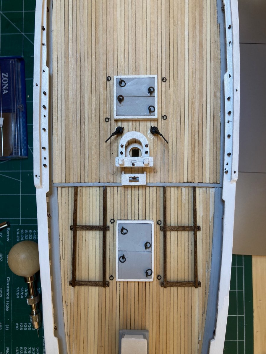
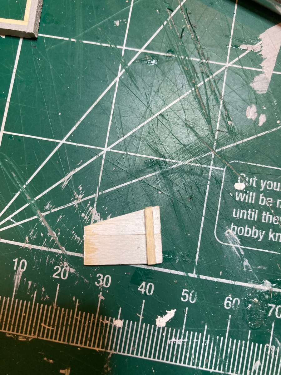
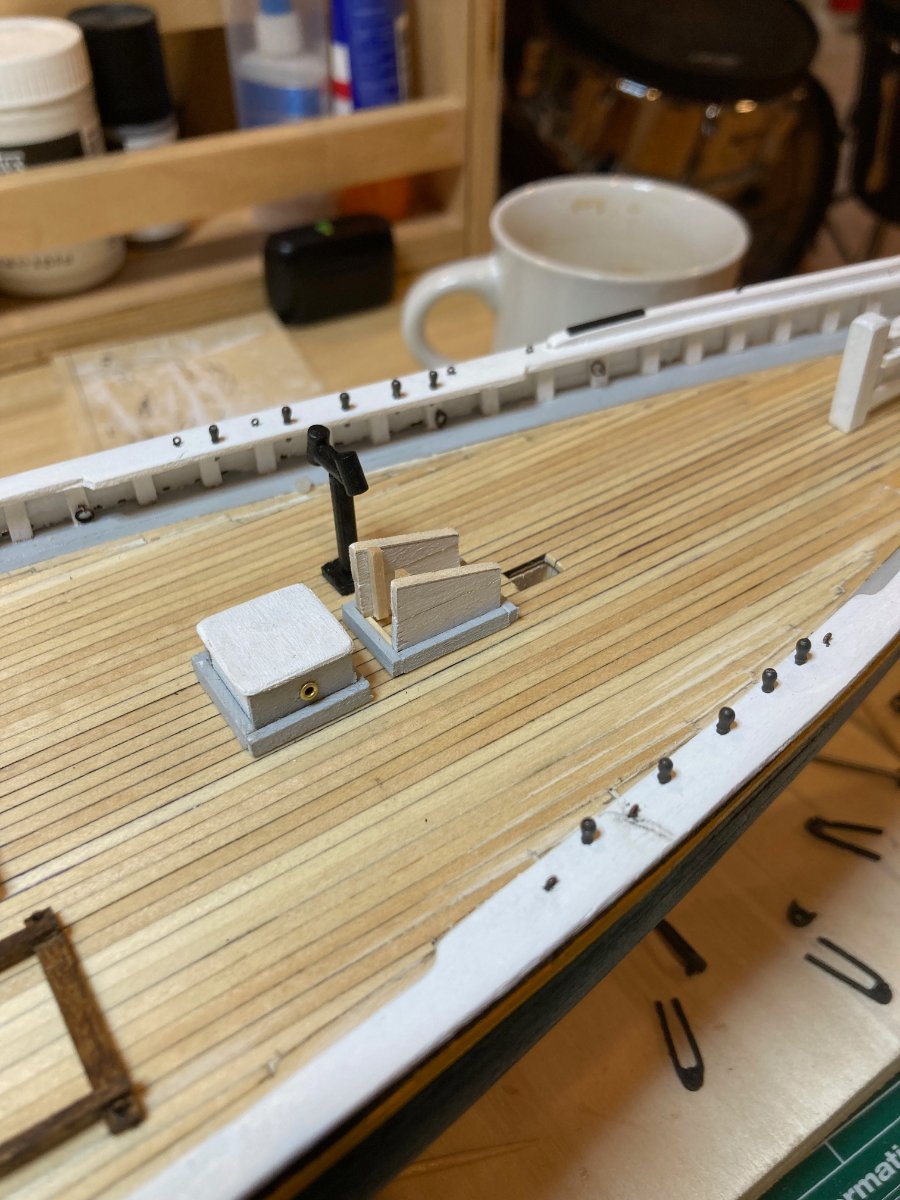
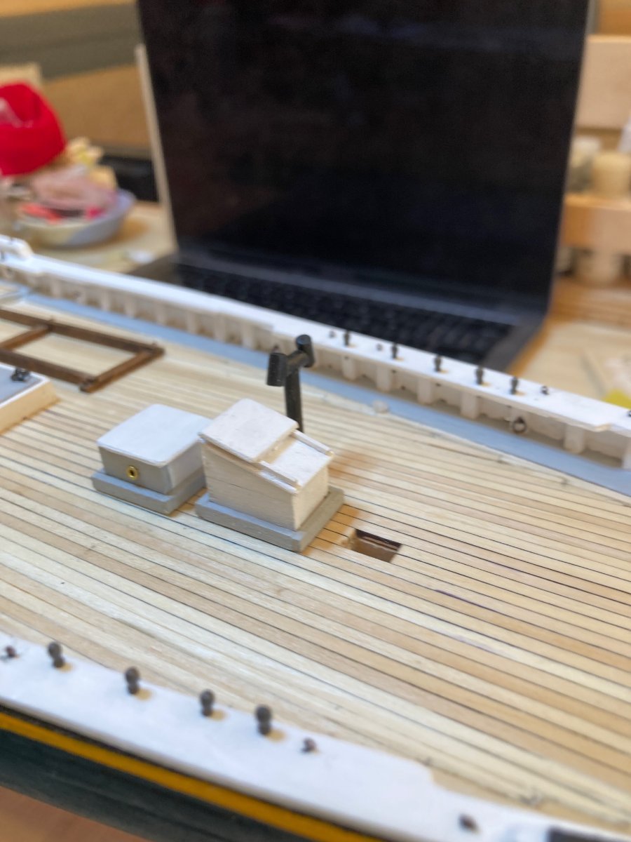
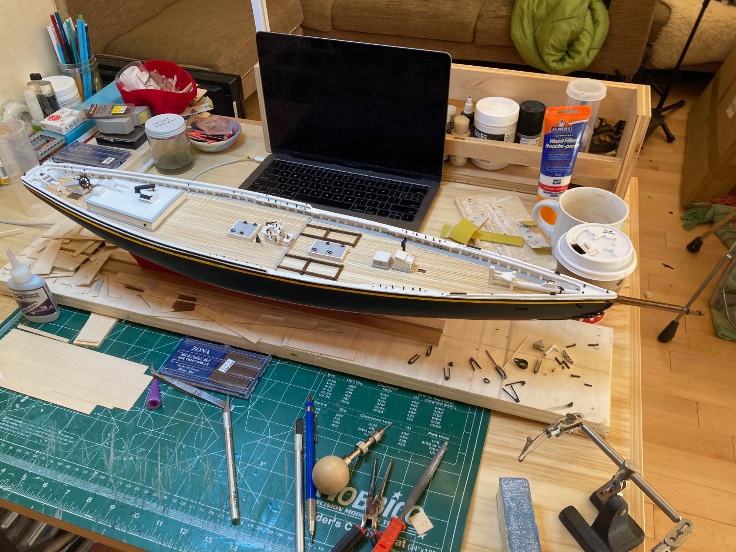
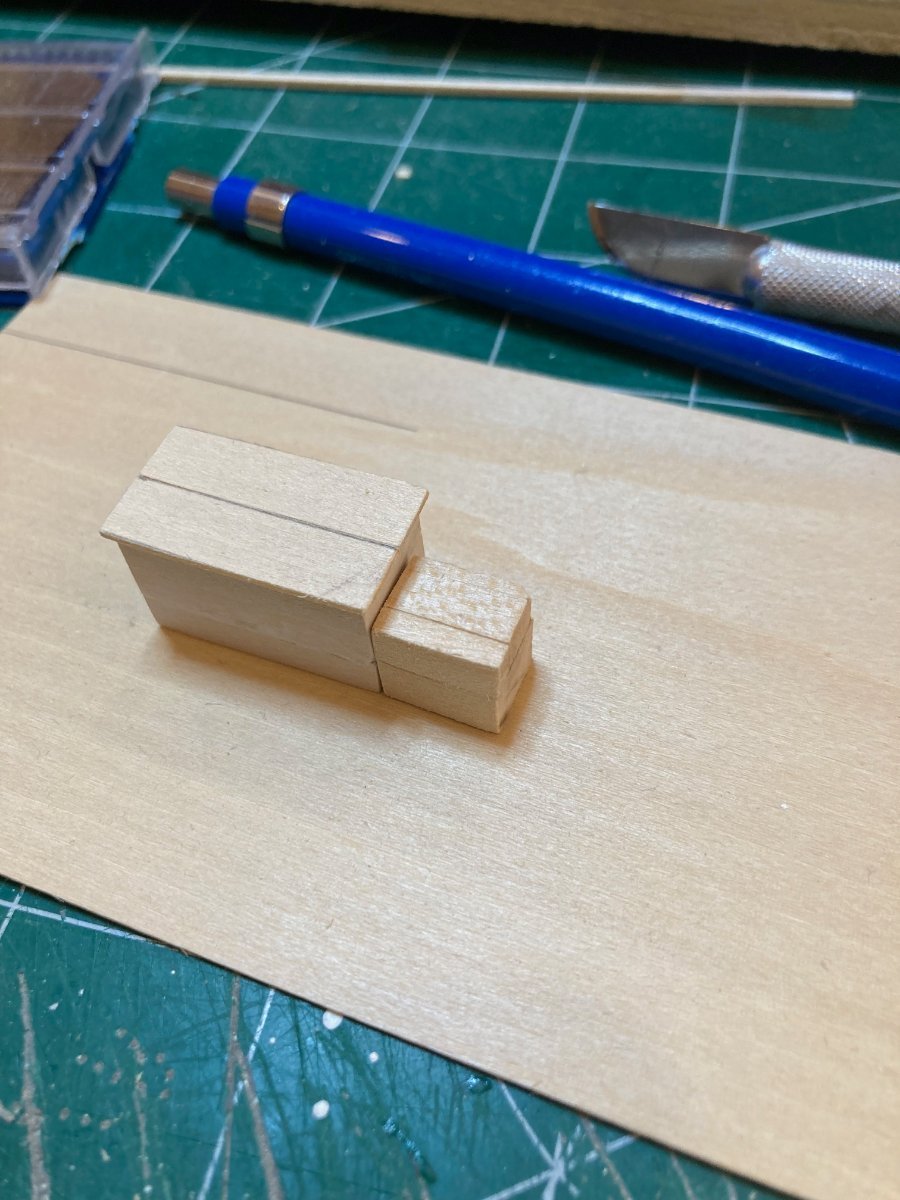
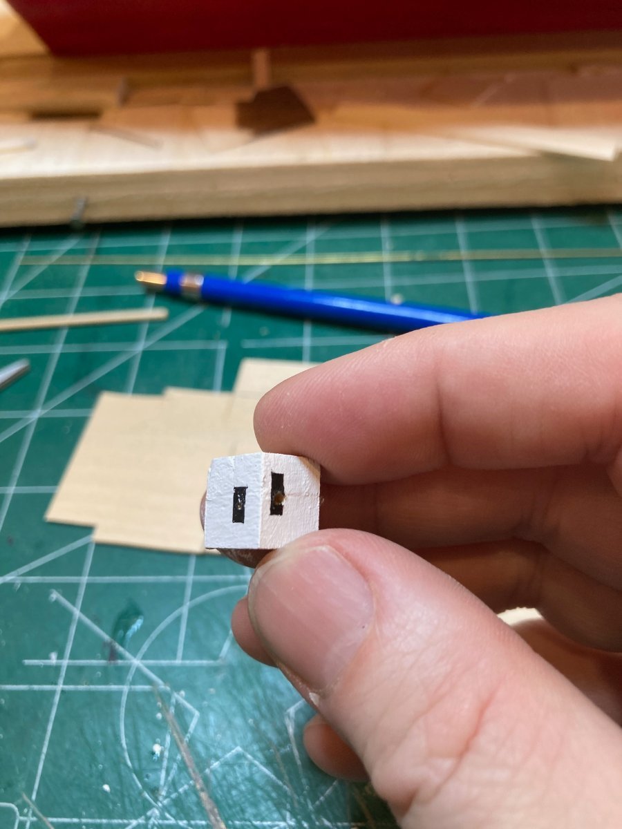
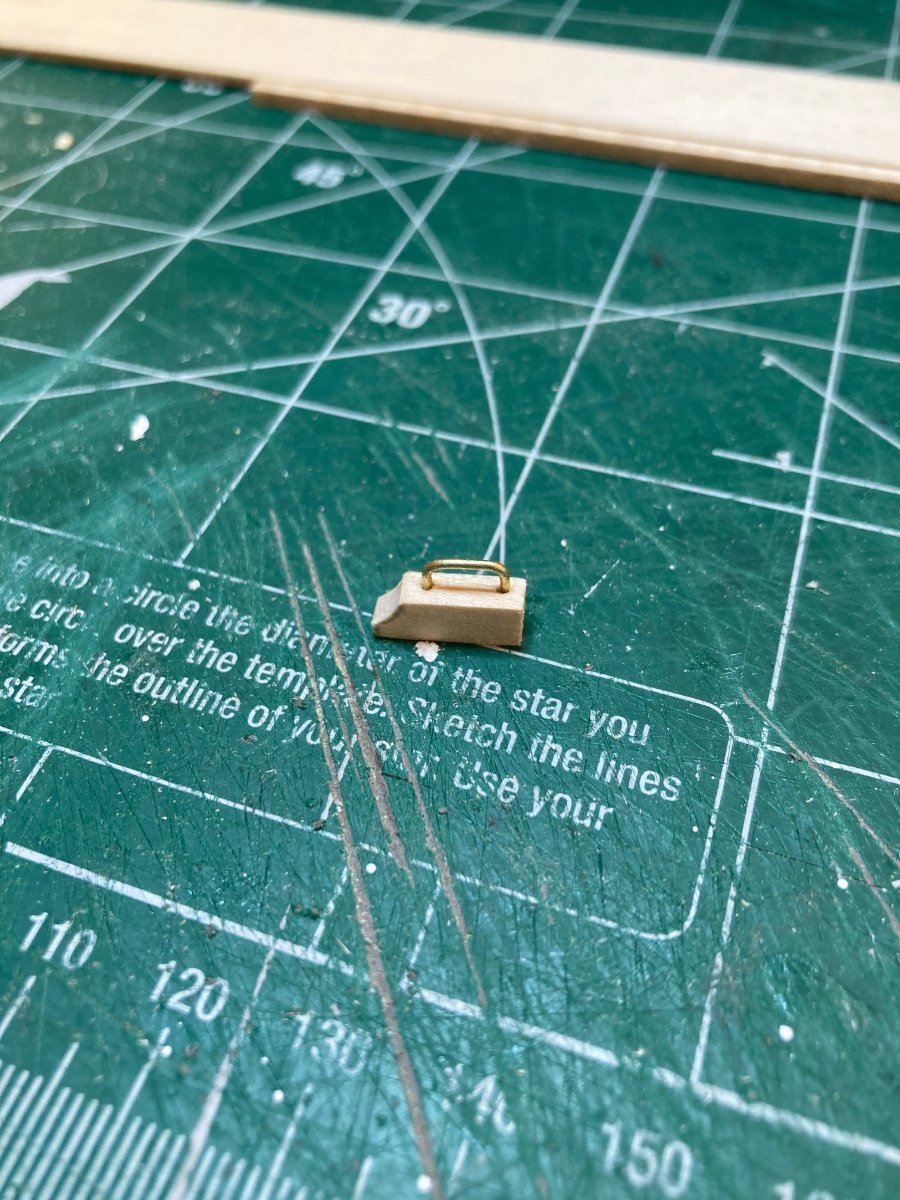
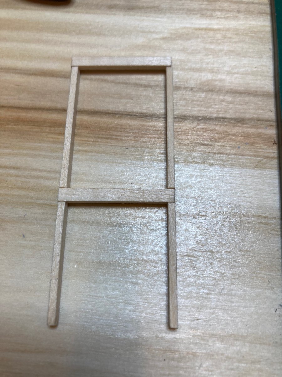
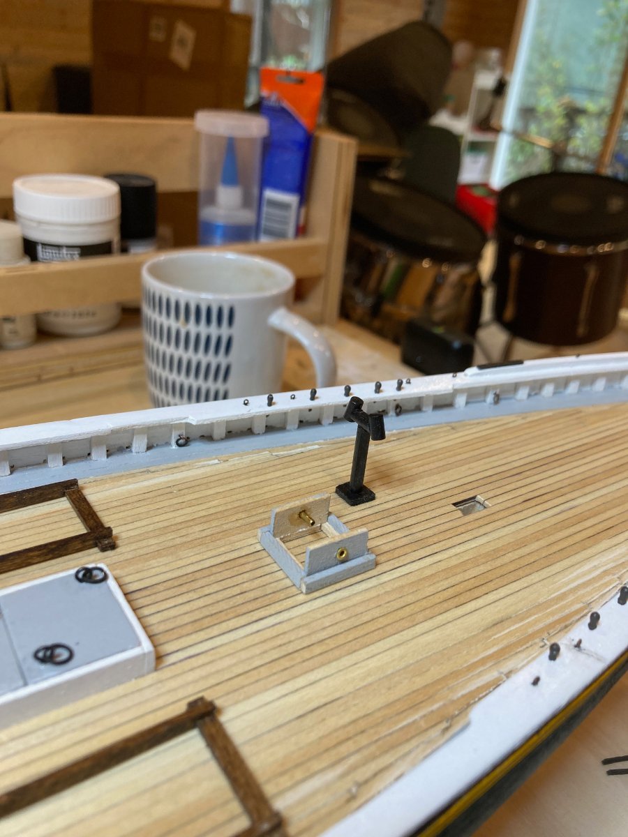
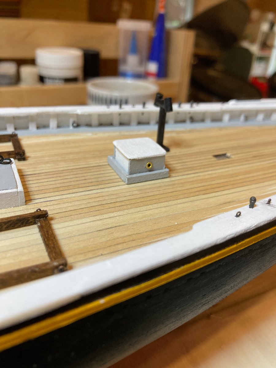
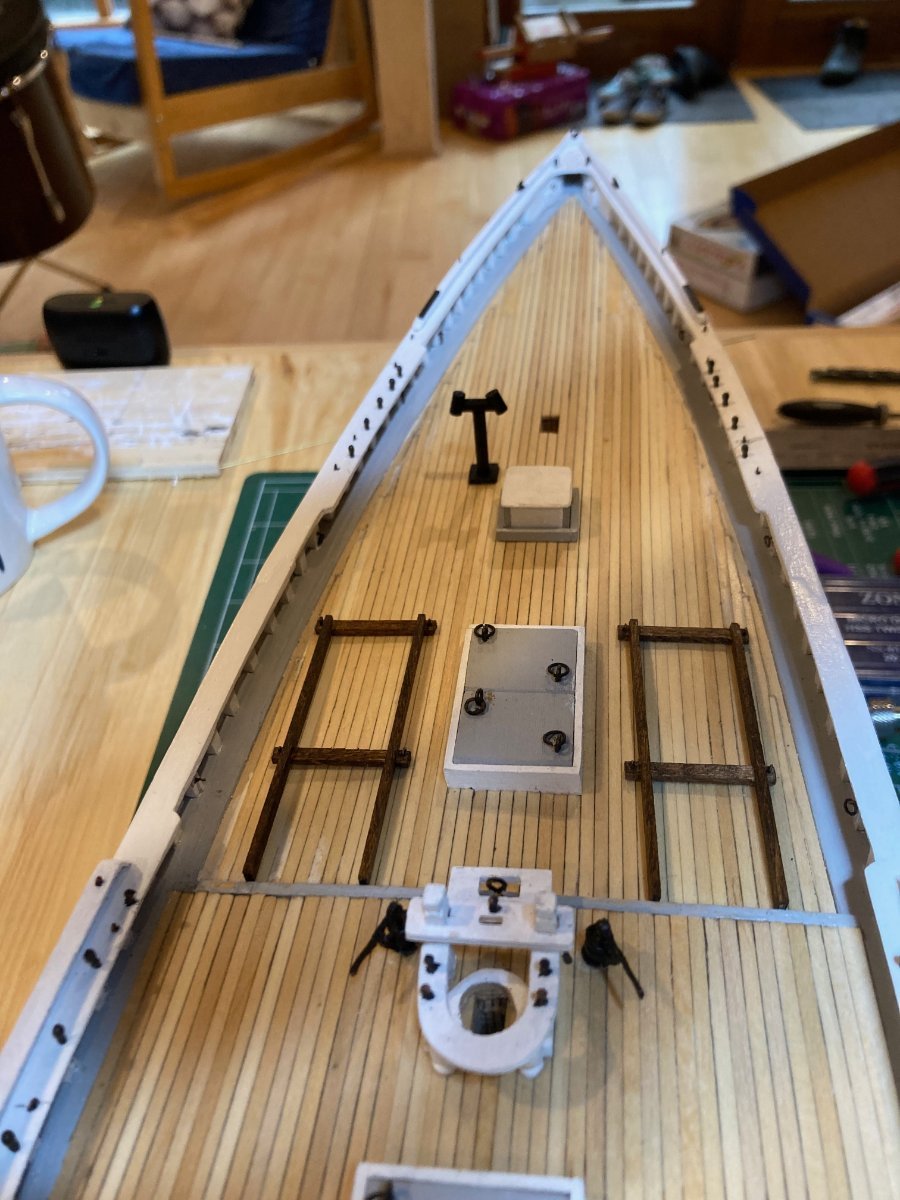
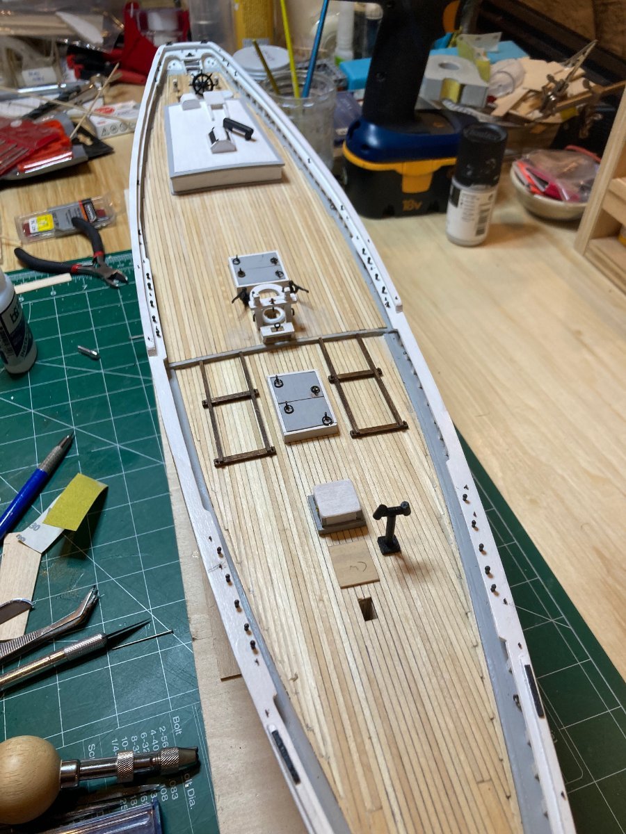
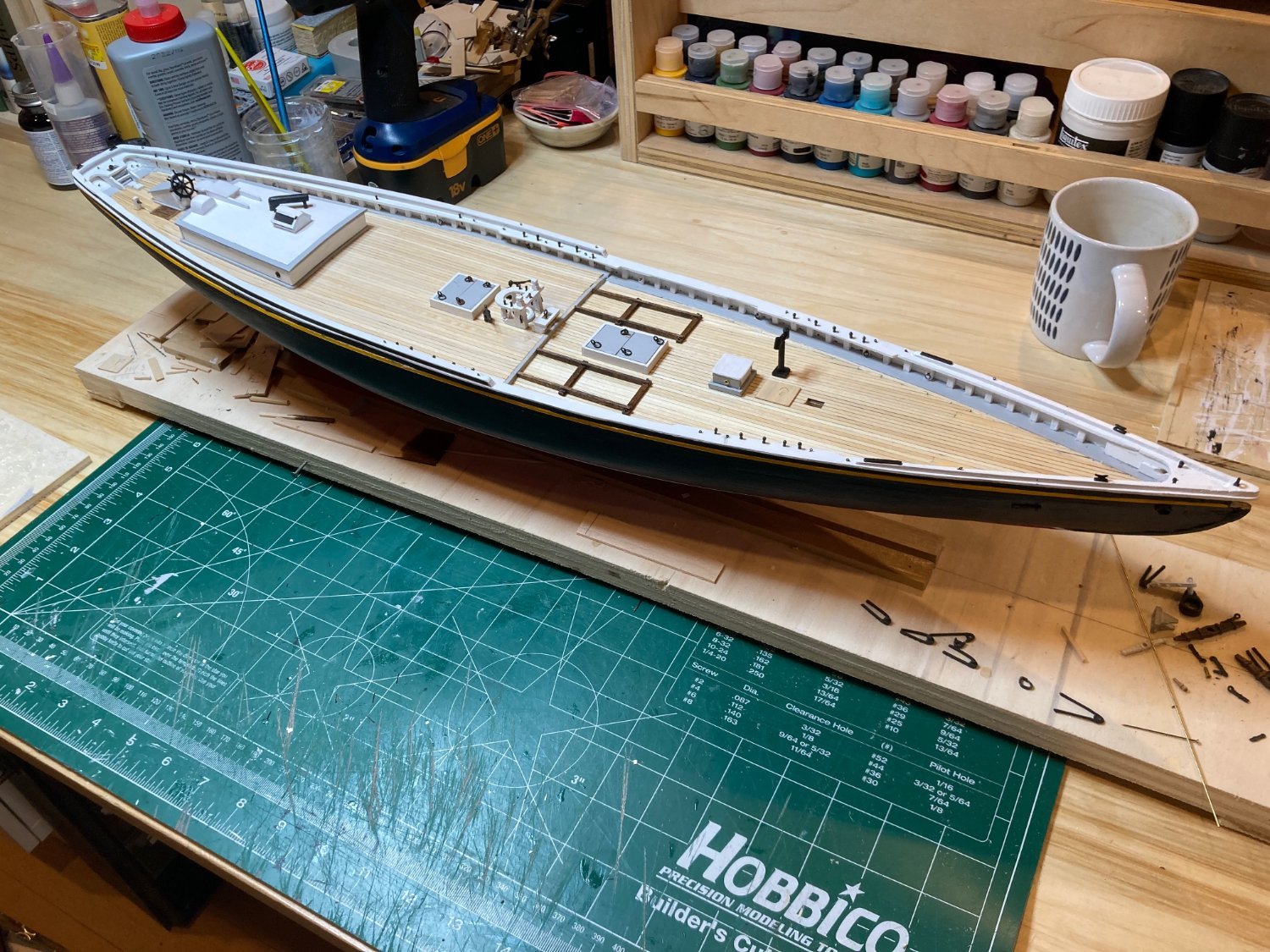
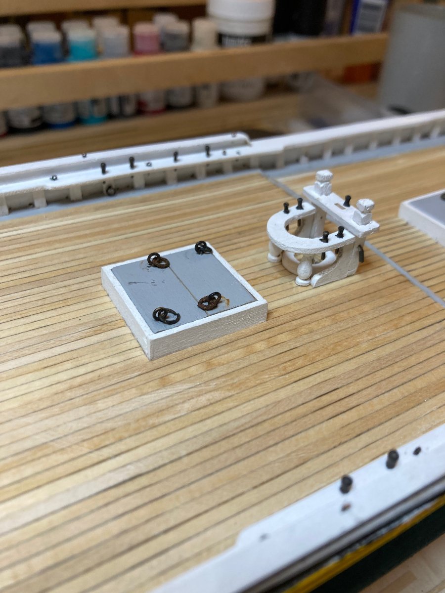
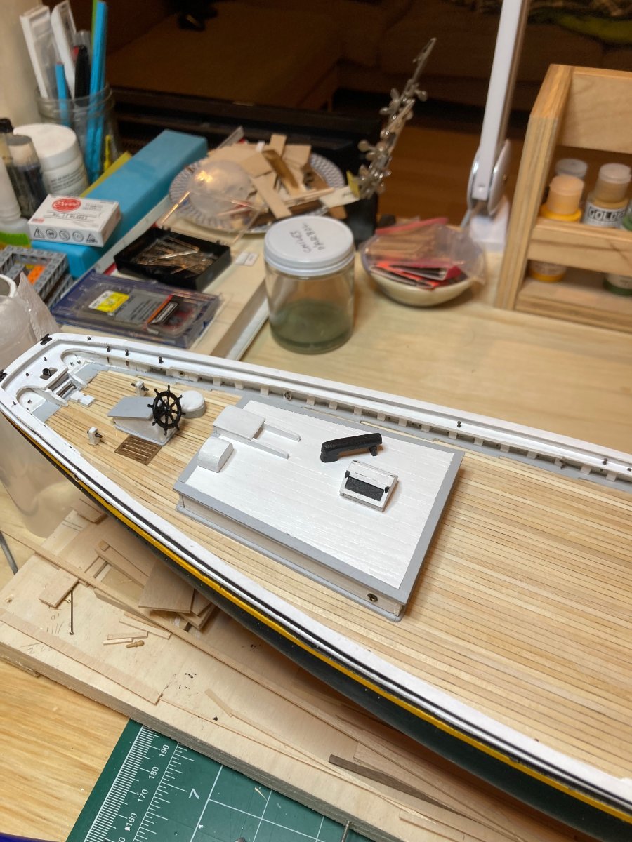
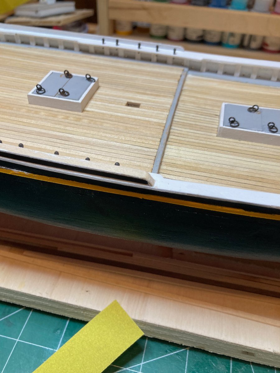
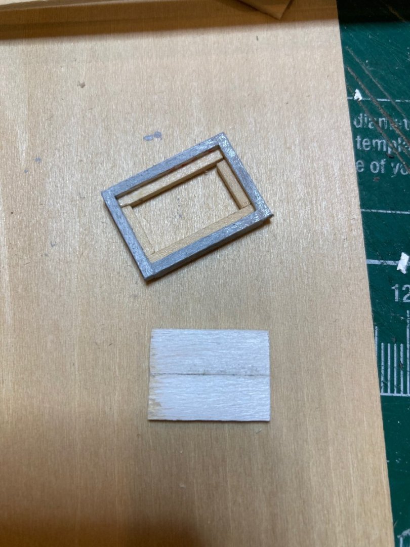
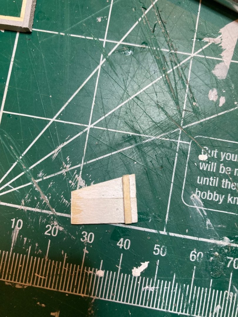
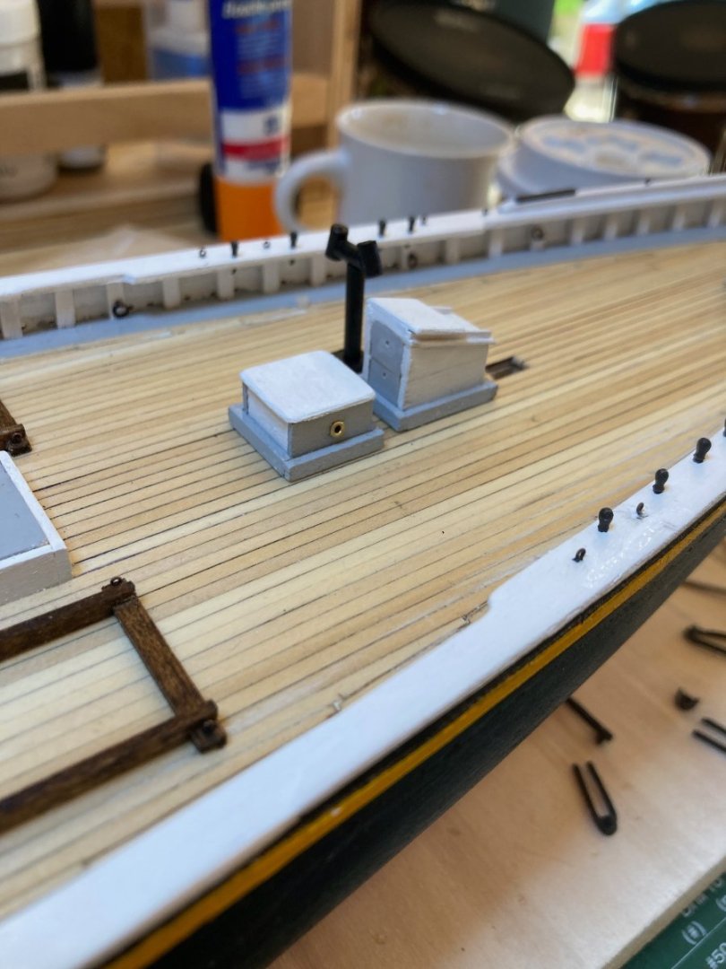
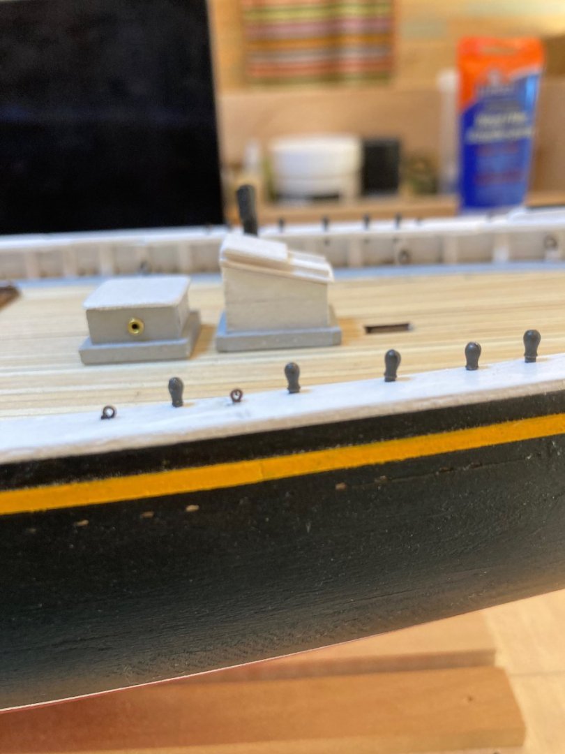
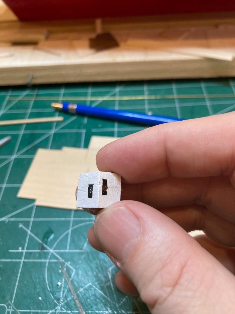
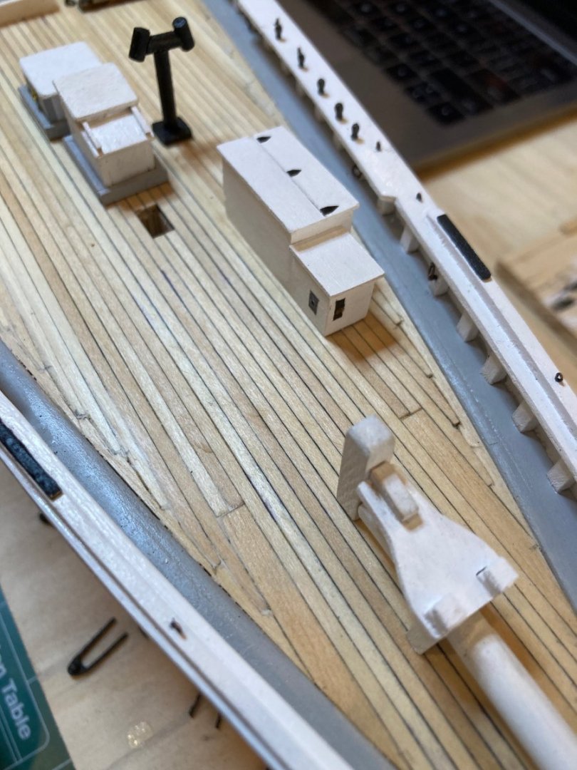
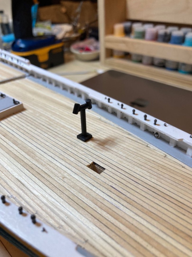
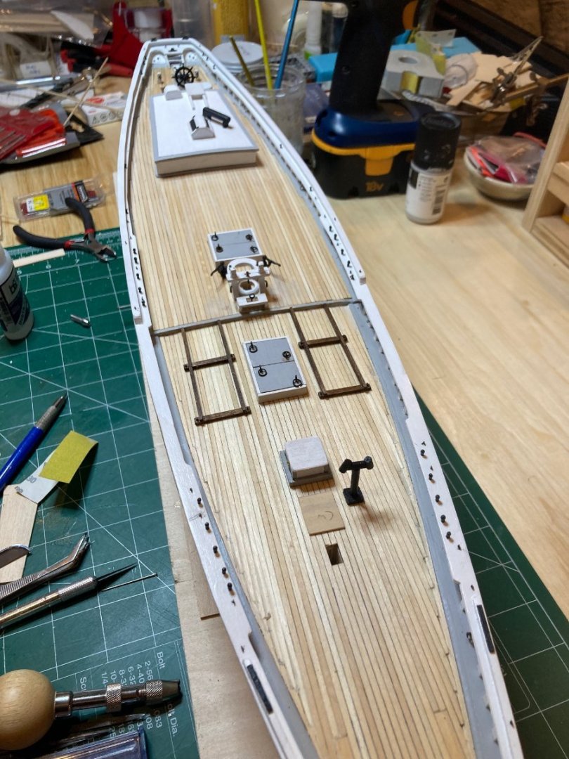
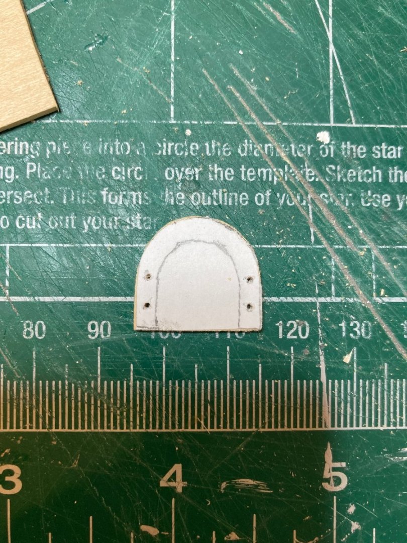
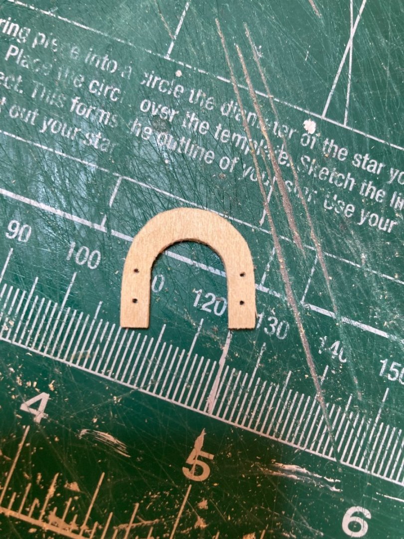
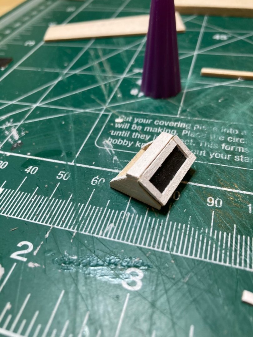
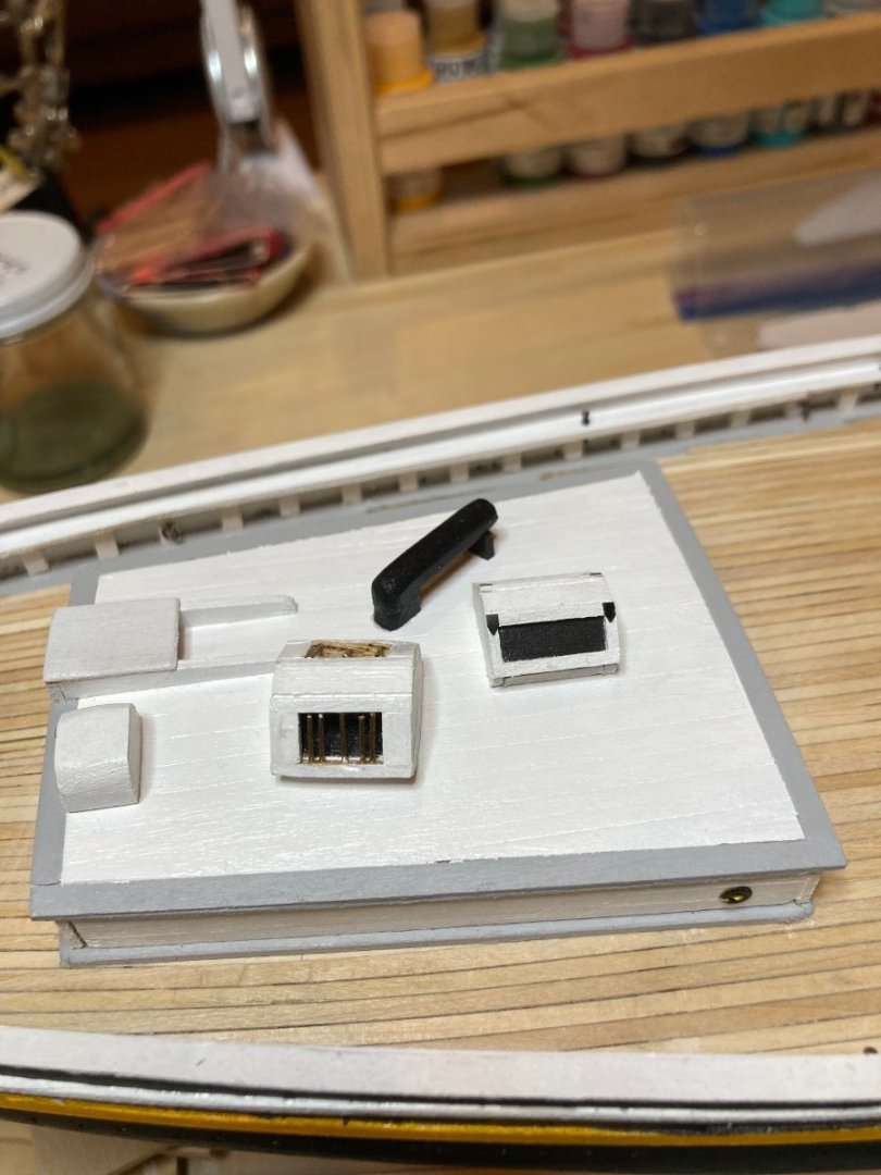
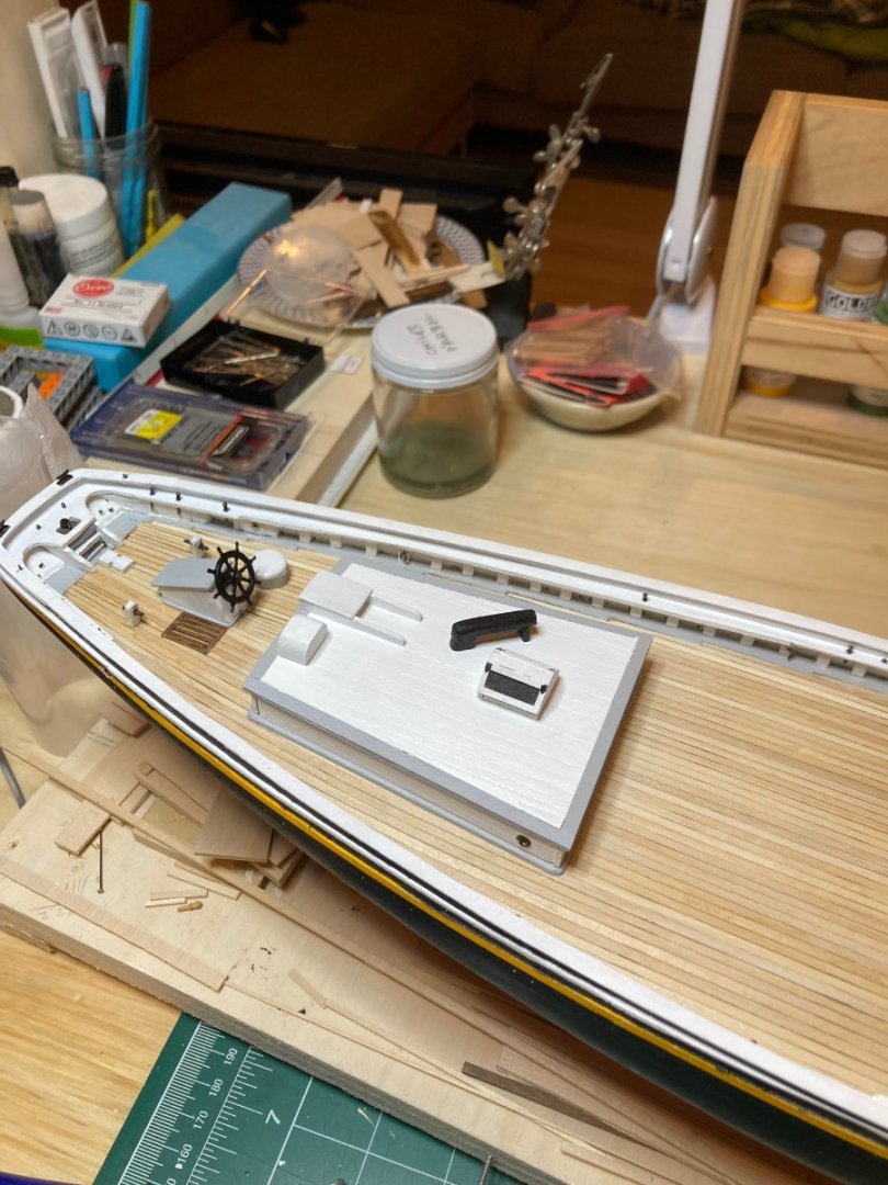
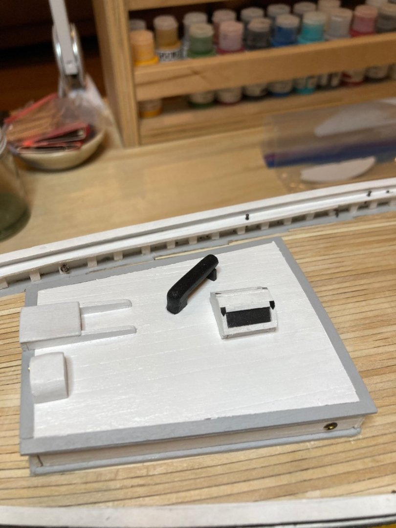
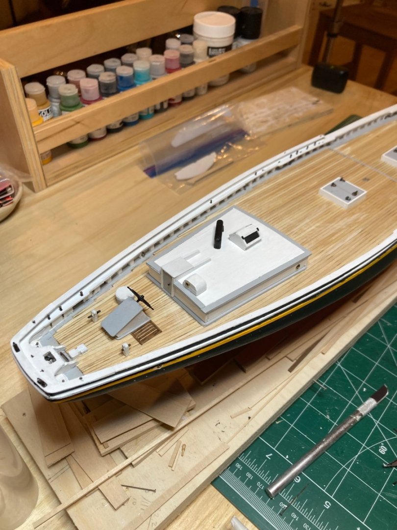
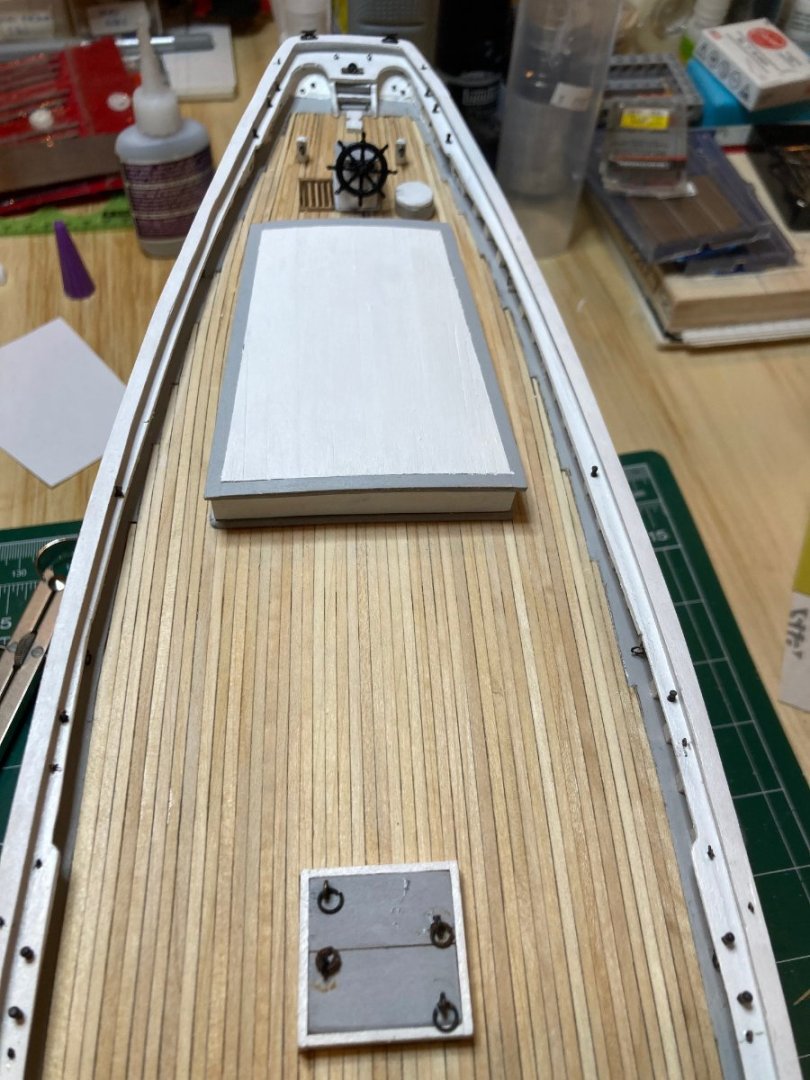
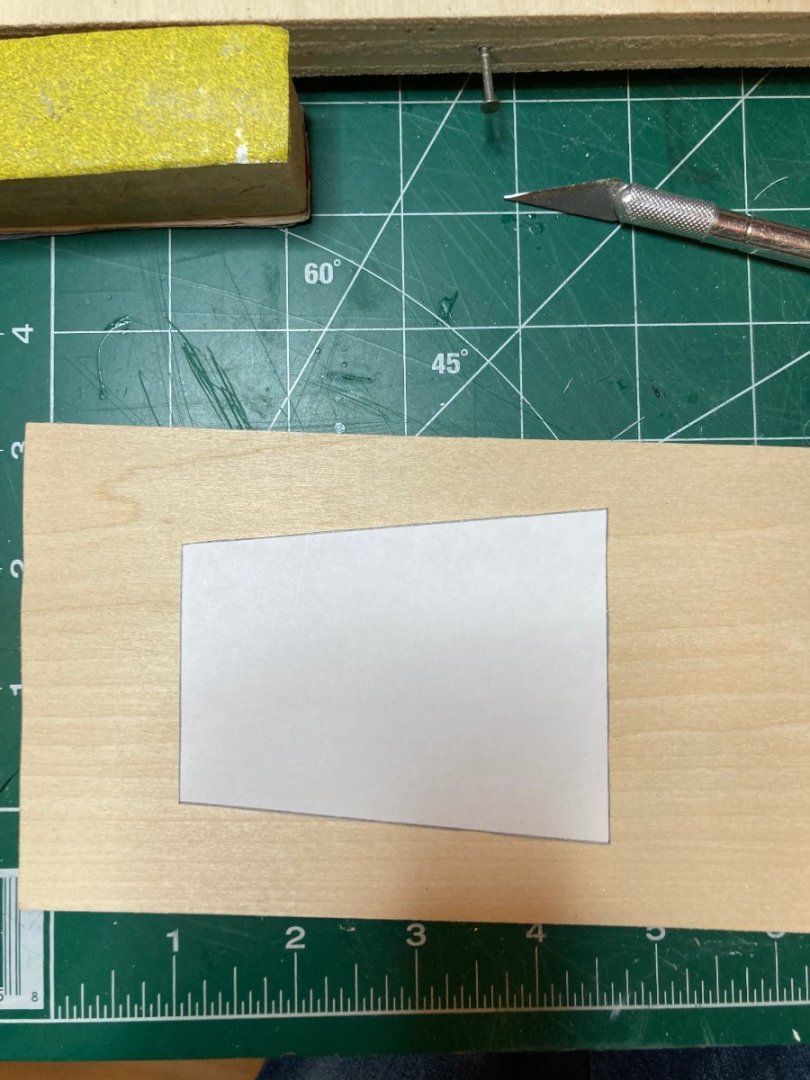
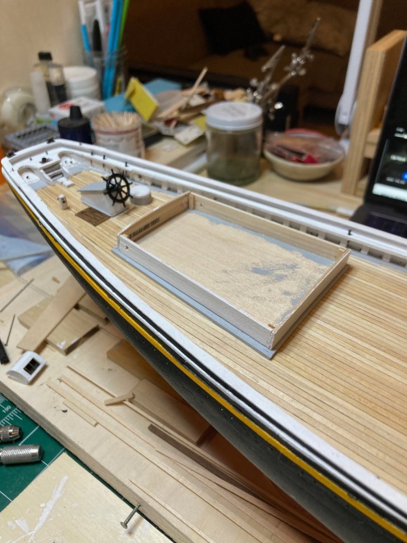
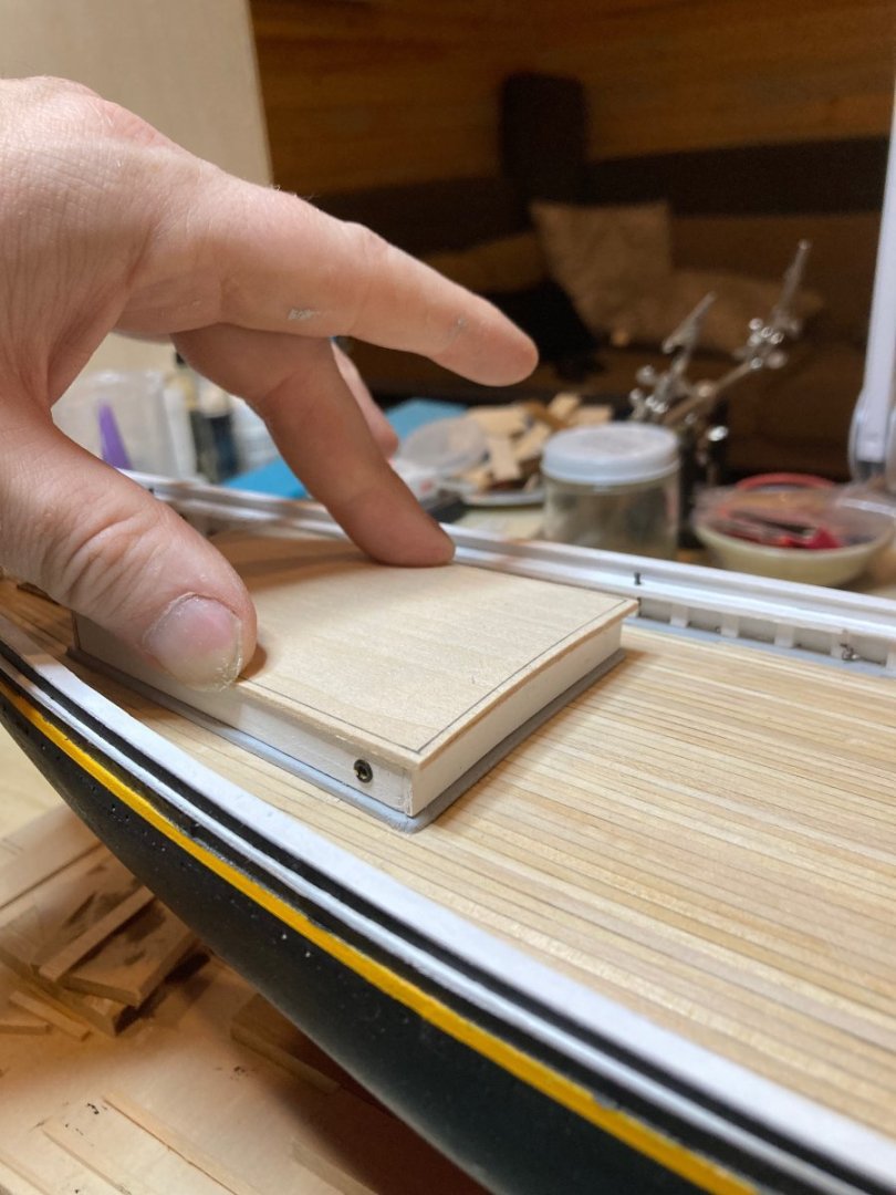
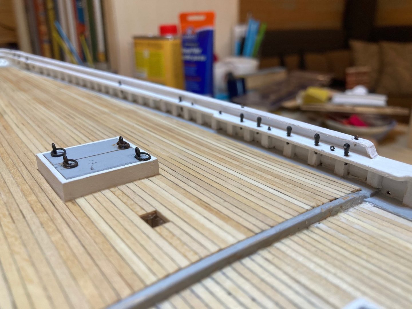
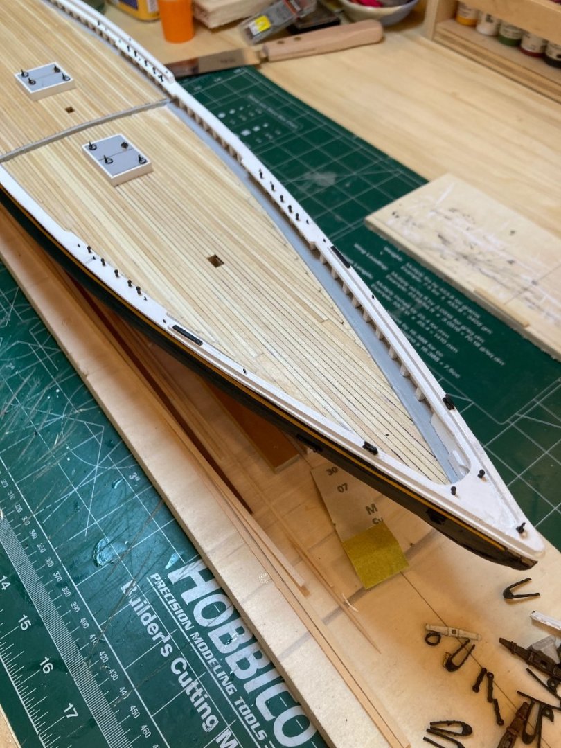
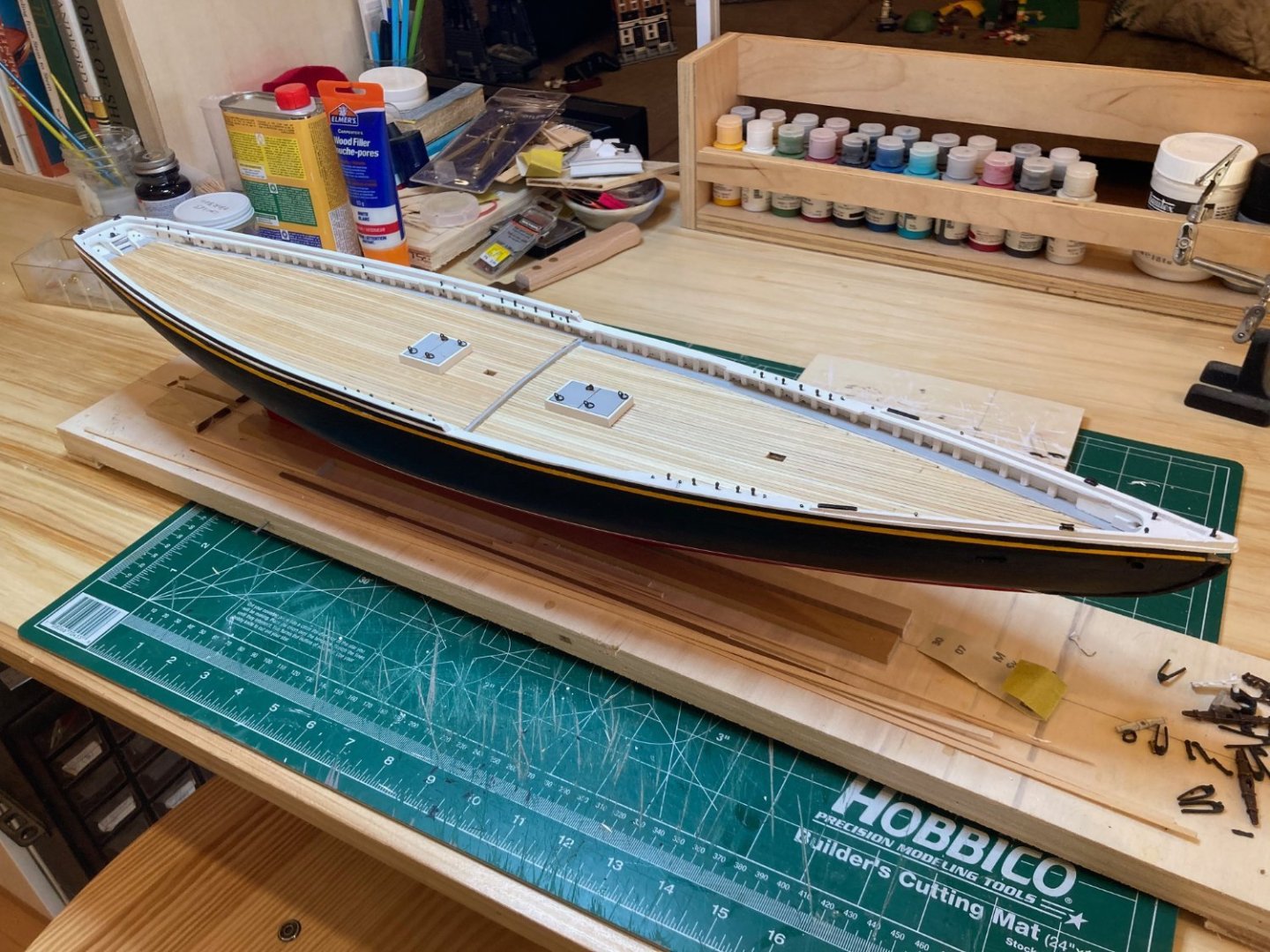
 Continuing with the foredeck....this update covers the forward companionway and engine box. Oh - and I added some ringbolts to the deck.... I ended up making the companionway twice - I probably should have made it a third time, but my patience ran out!! I approached this the same way I did with the skylight. I glued up a couple of 1/16 x 1/4" strips for the sides and used the same material for the panels. I glued a couple of 1/16" square strips on the inside of the sides, set 1/16" back from the aft edge to act as a stop for the panels. The engine box I built up out of 6 pieces of 1/4" x 3/16" basswood (for the larger section) and a tetris style assembly of random wood strips to get the proper dimensions. Once these were filled, sanded and finished, I marked out the two openings on the smaller section, drilled holes to eventually receive the rod for the winch (starboard side) and for the anchor chain (forward). The two sections were glued together, the seam filled and the entire thing painted and lidded. I used, once again, 1/16" pinstripe tape to simulate the hinges. The assembly is not glued to the deck yet, since I want to first construct the jumbo jibboom rest, winch and windlass to make sure all these parts are situated correctly relative to one another....I only have a couple of small jobs to do before moving on to the windlass, winch, etc., which is going to be a challenge for me....I've been spending a bit of time over the last couple of weeks wrapping my head around these items and I have a couple of possible approaches in mind - but that is for the future! Until then - enjoy the photos and happy modelling hamilton
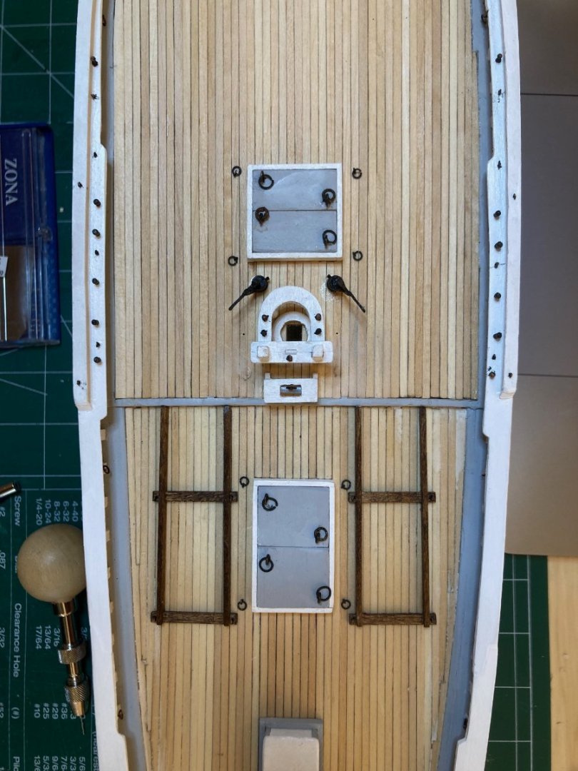


-
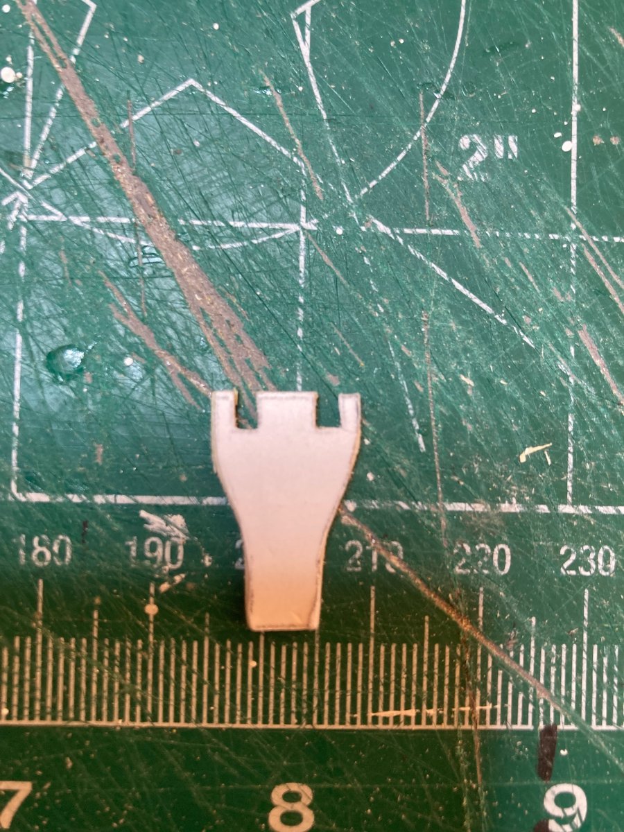
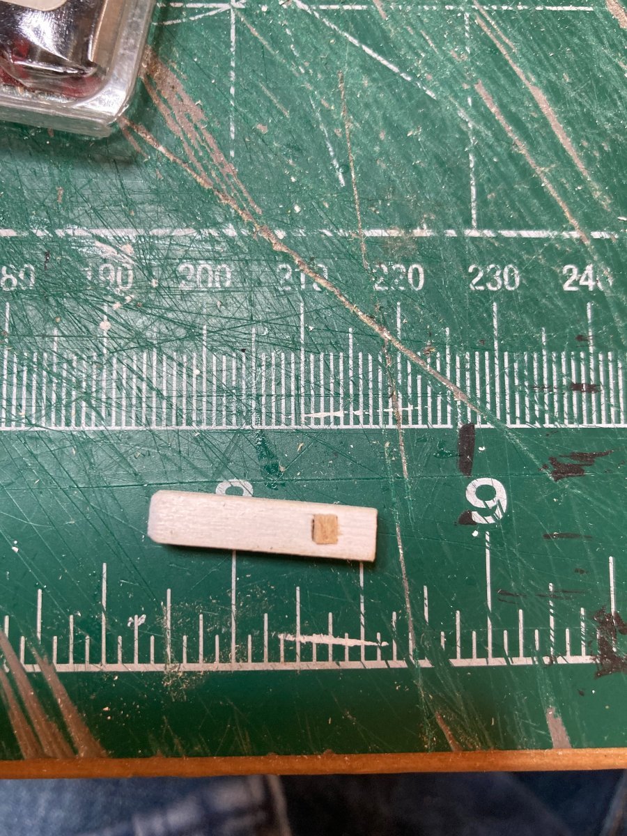
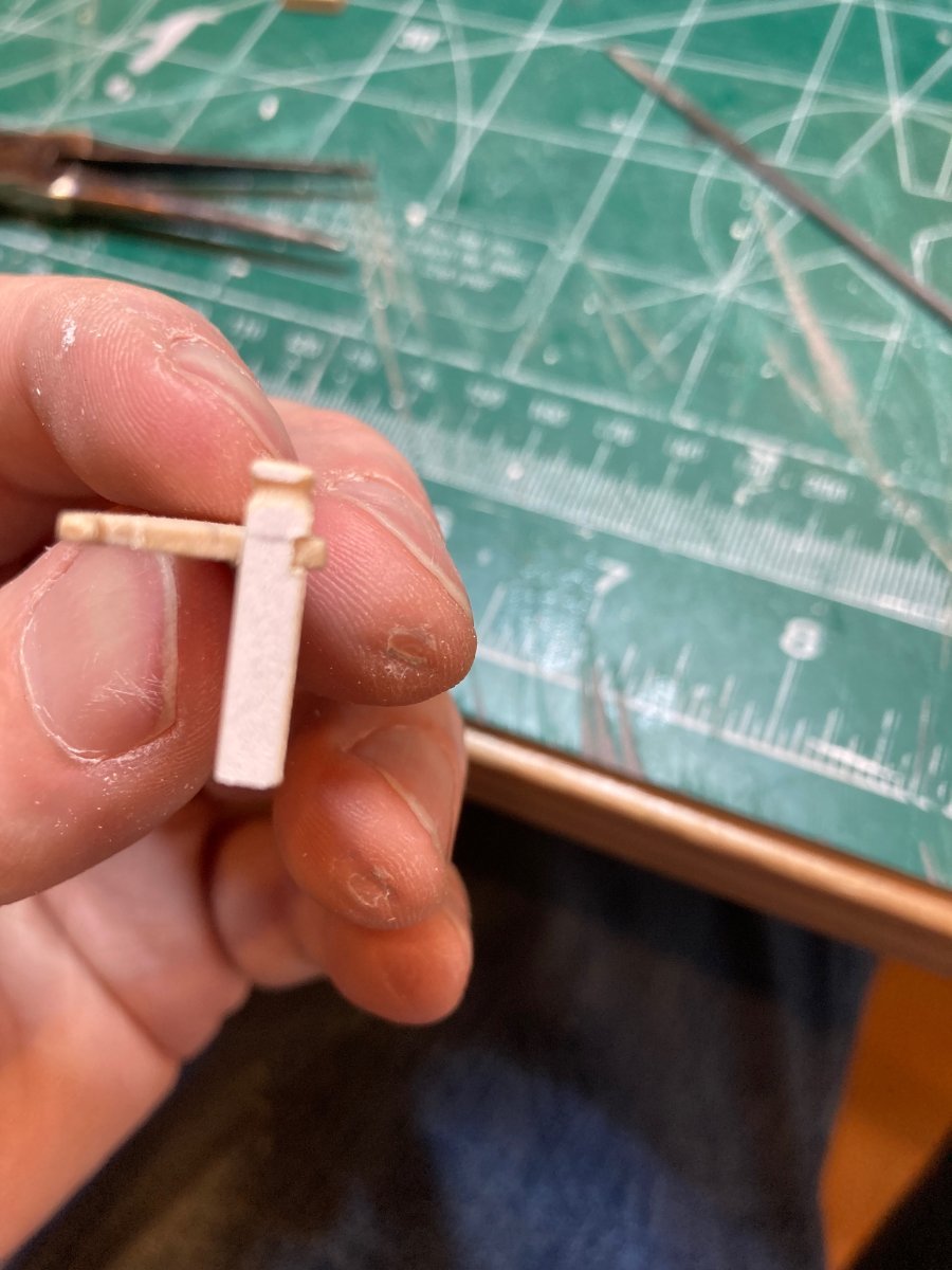
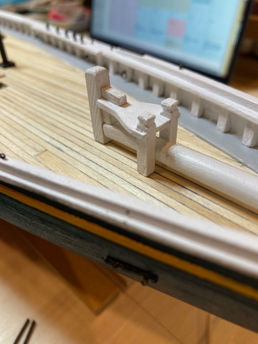
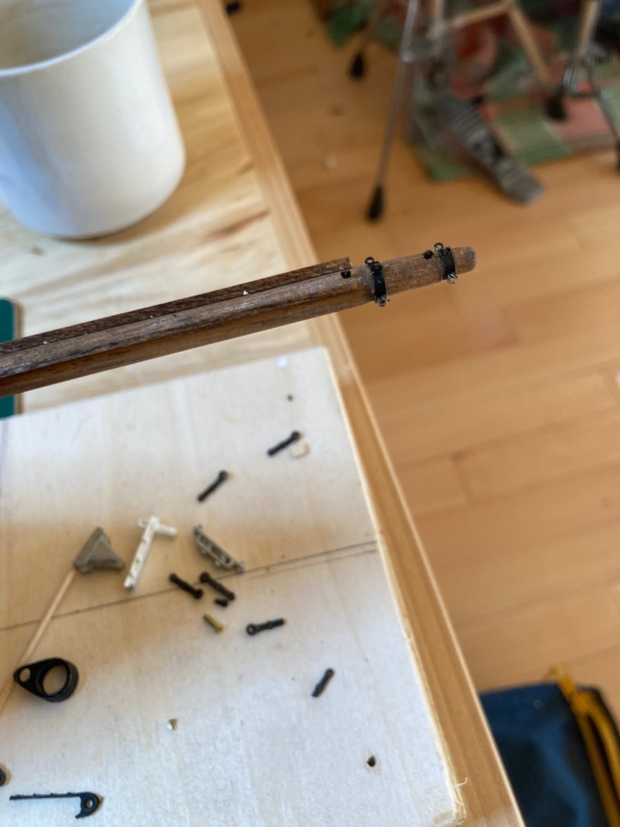
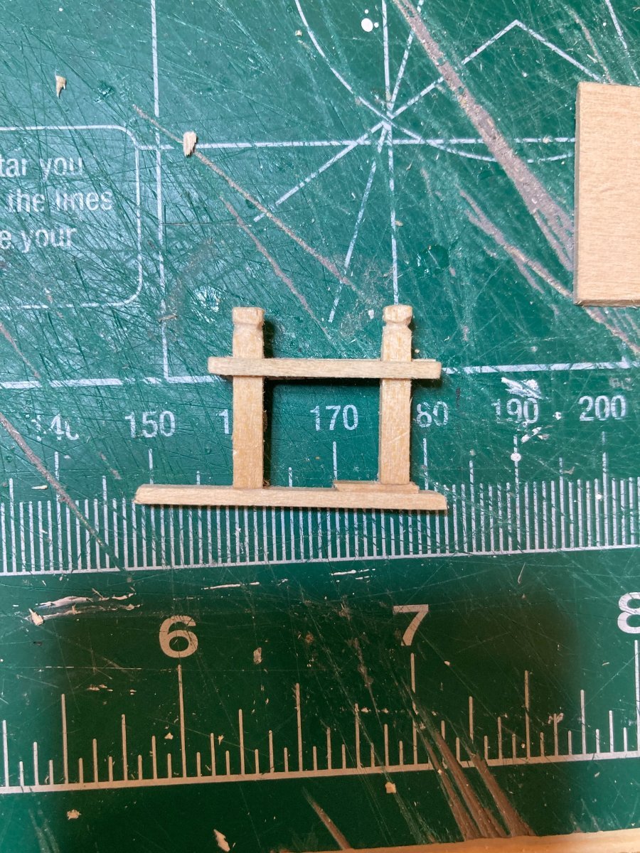
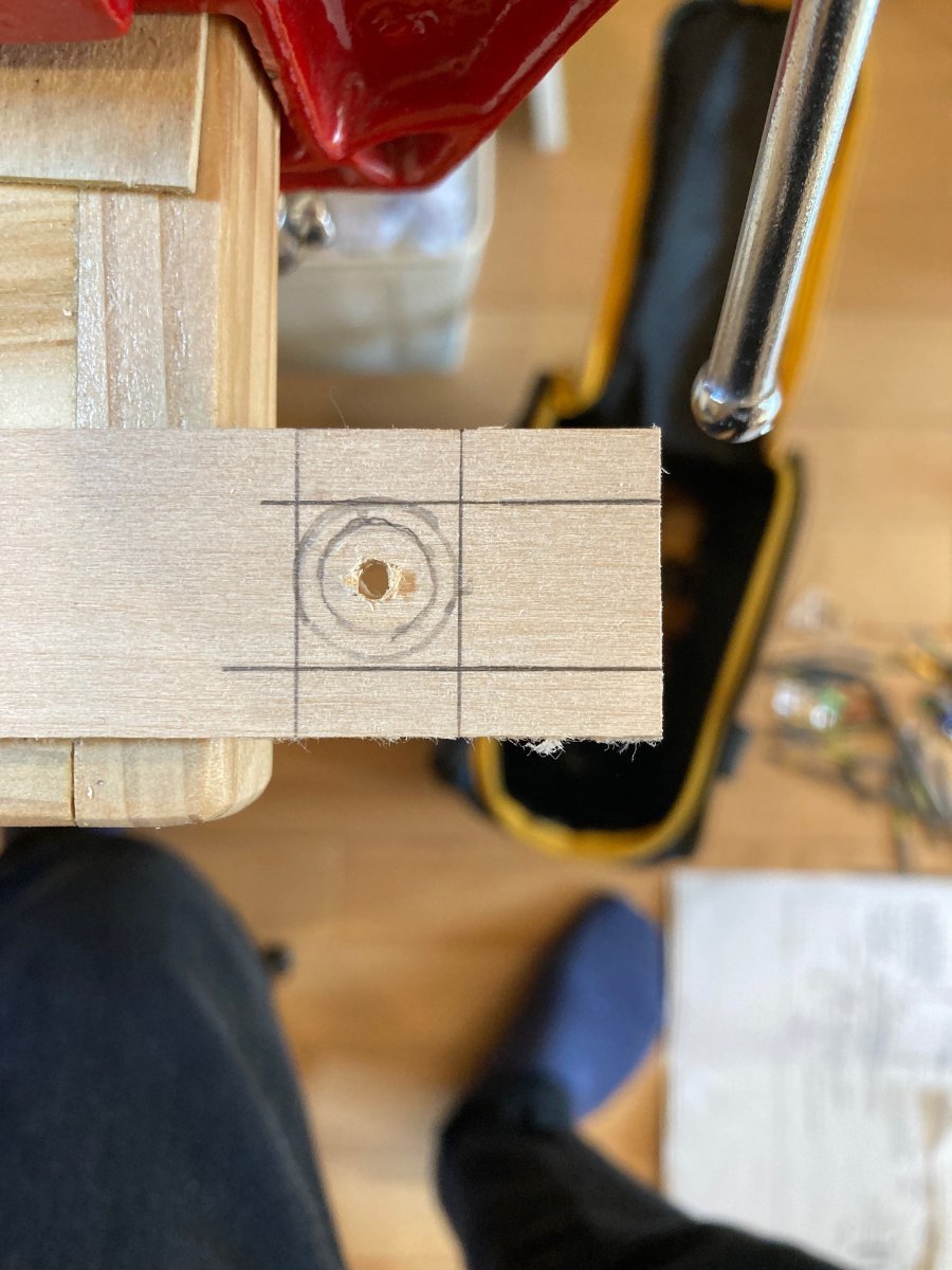
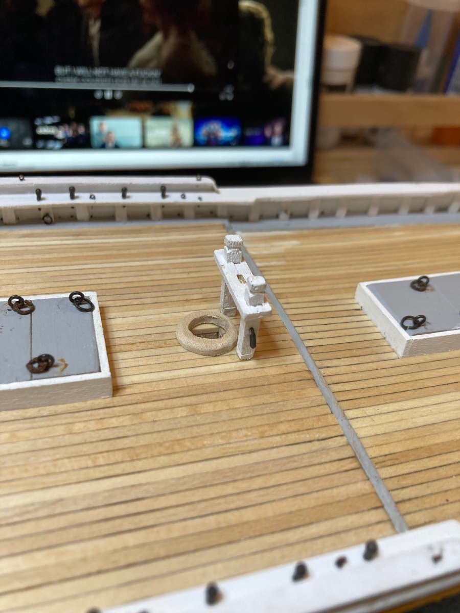
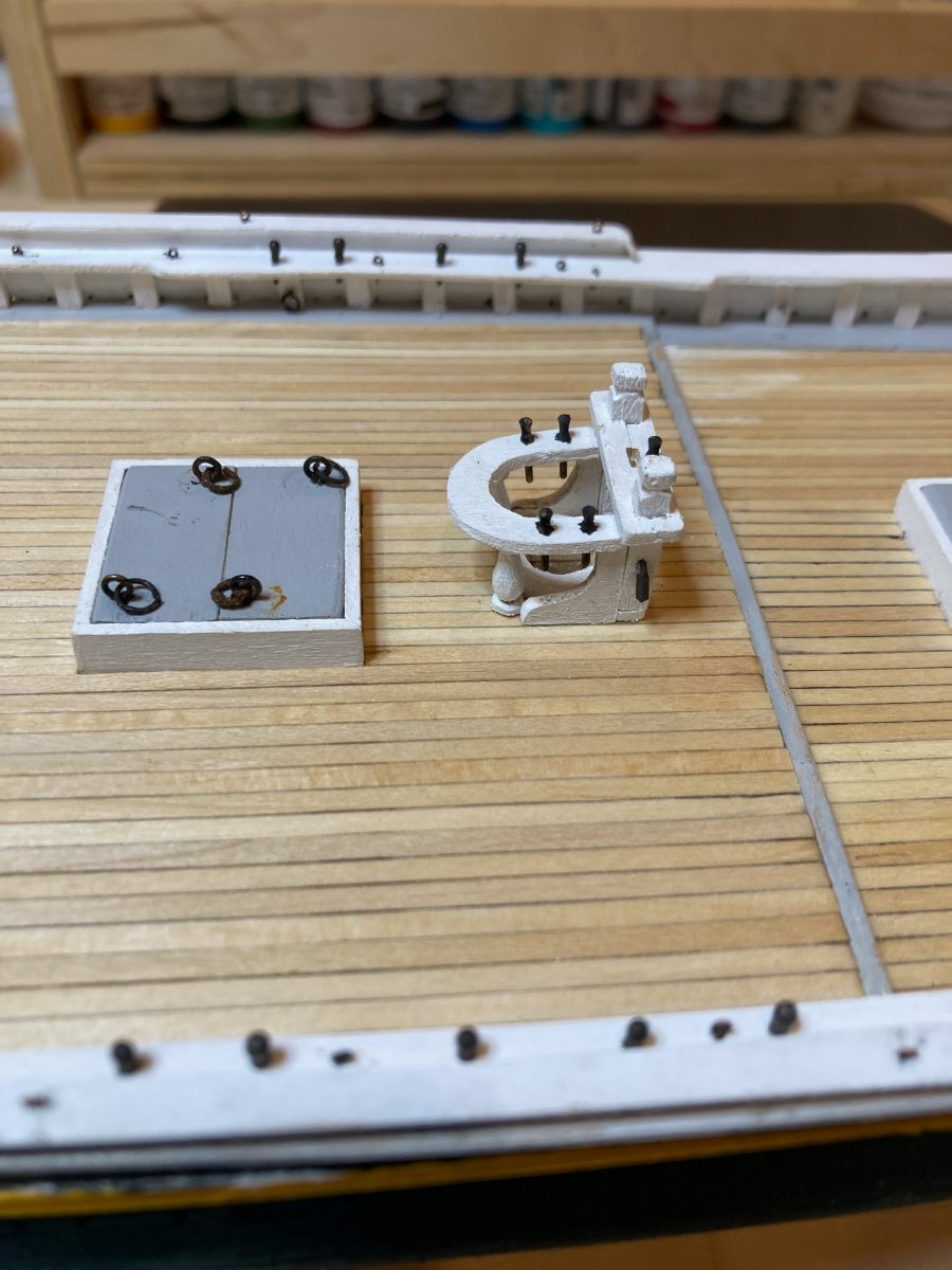
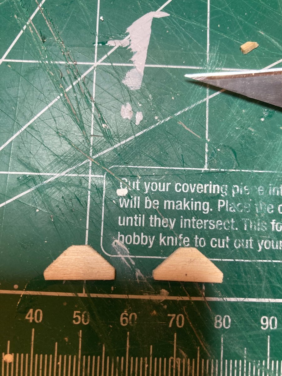
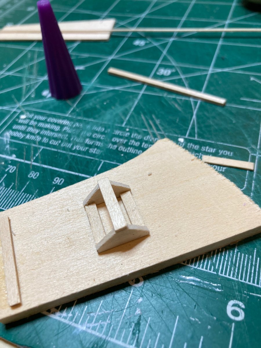
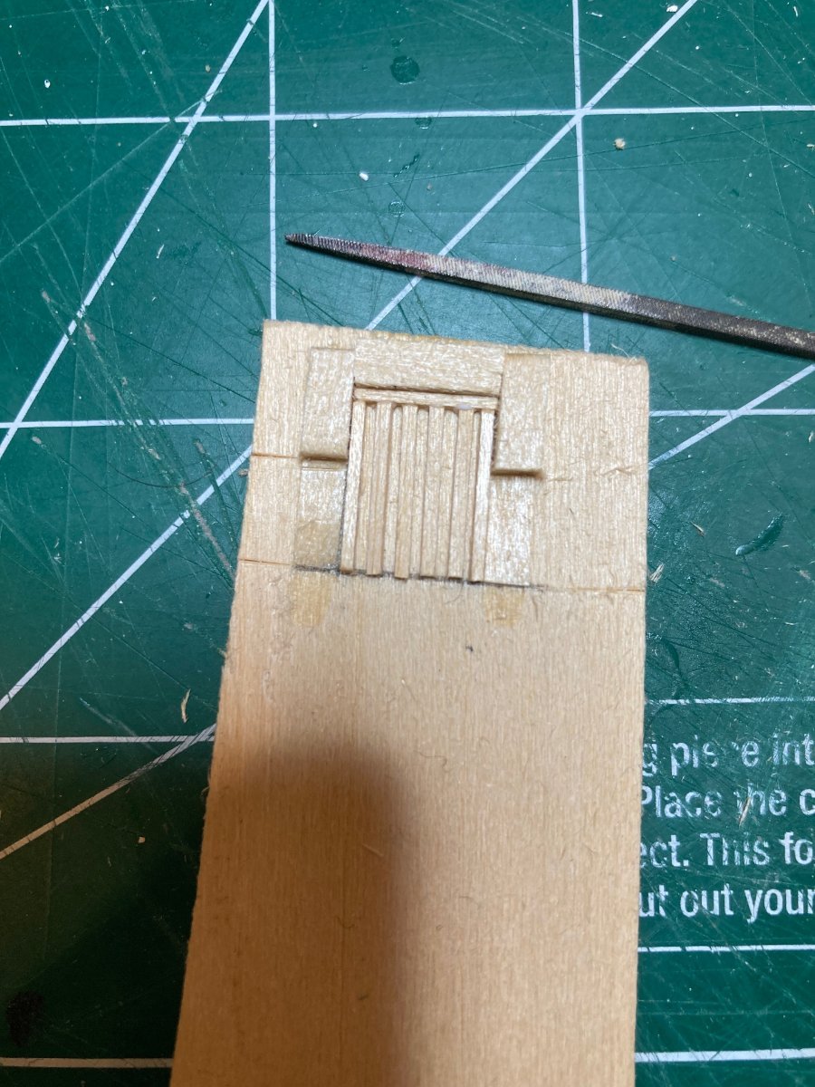
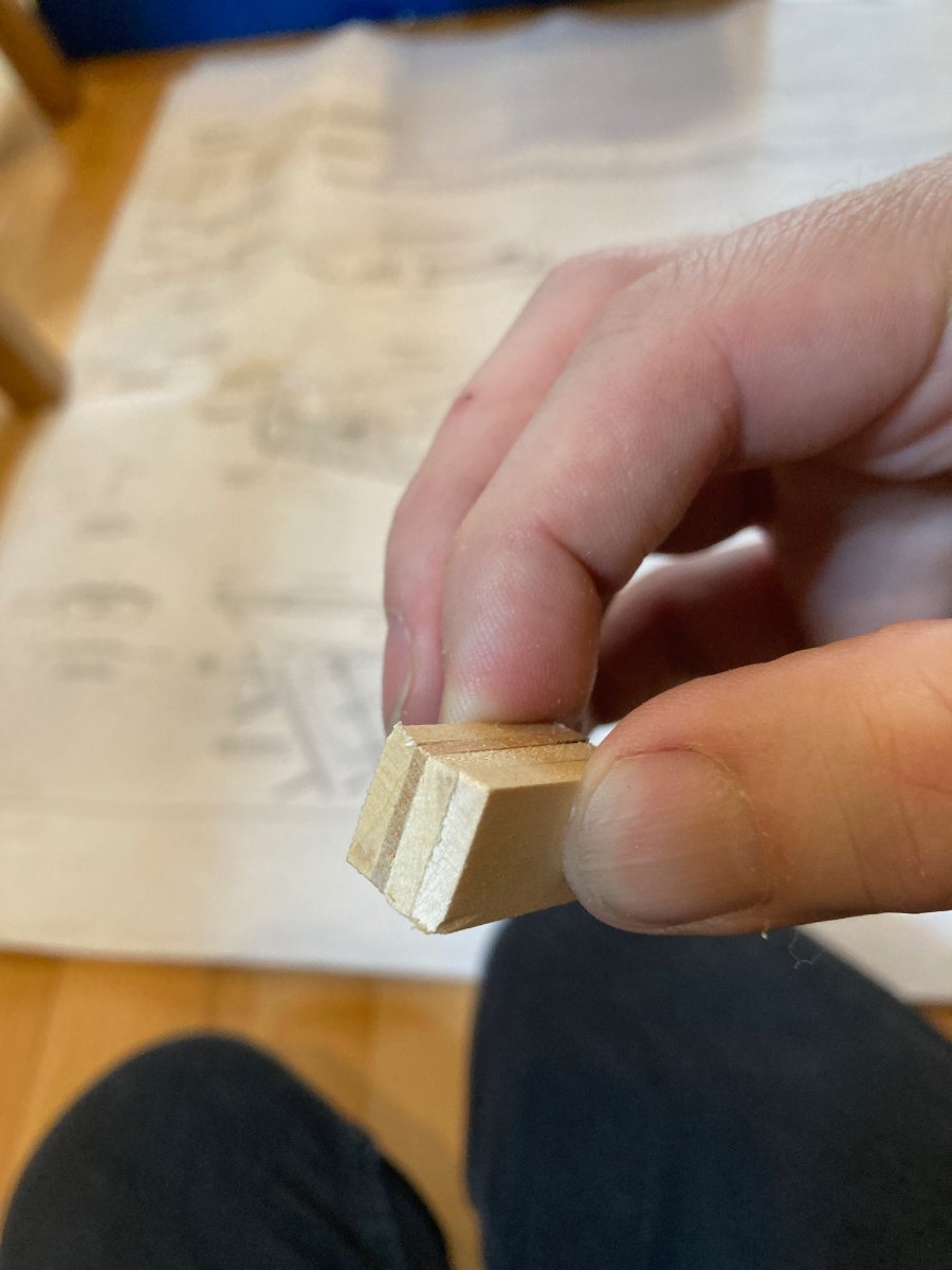
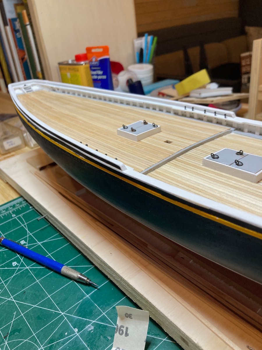
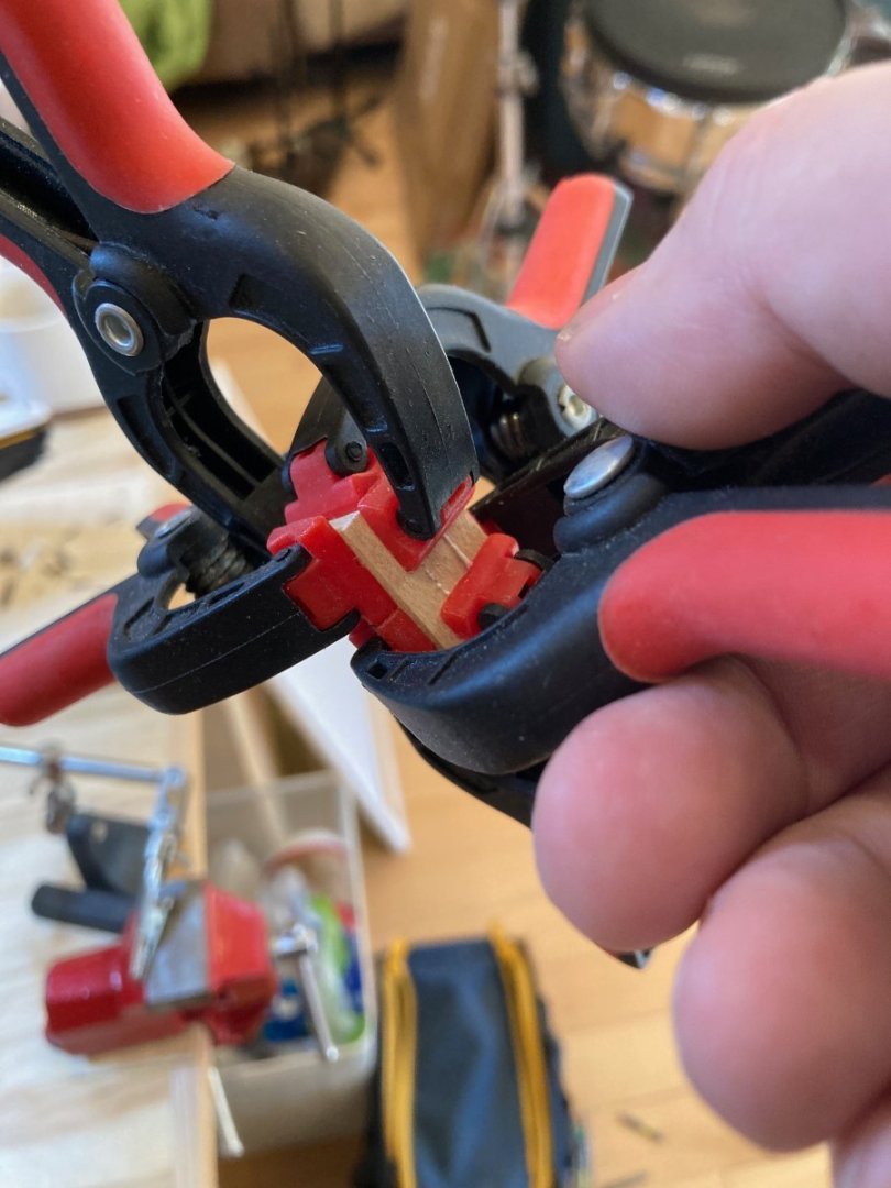
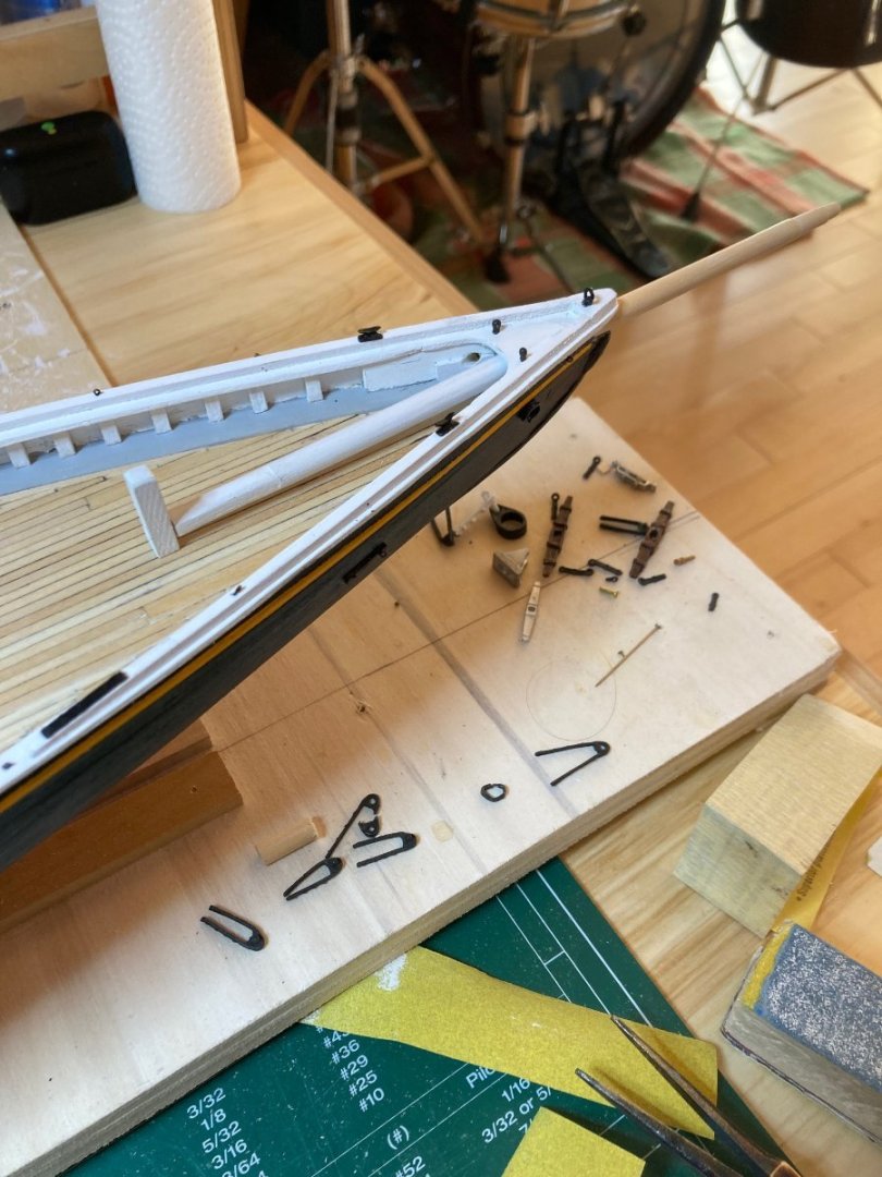
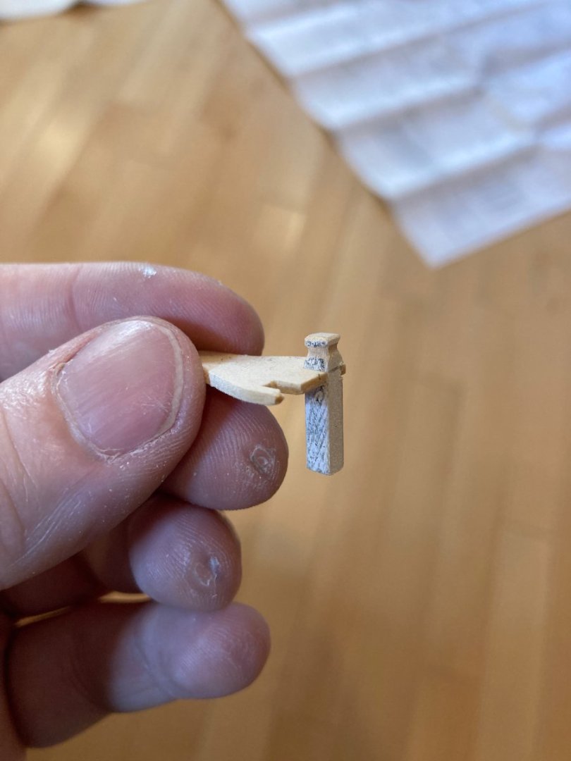
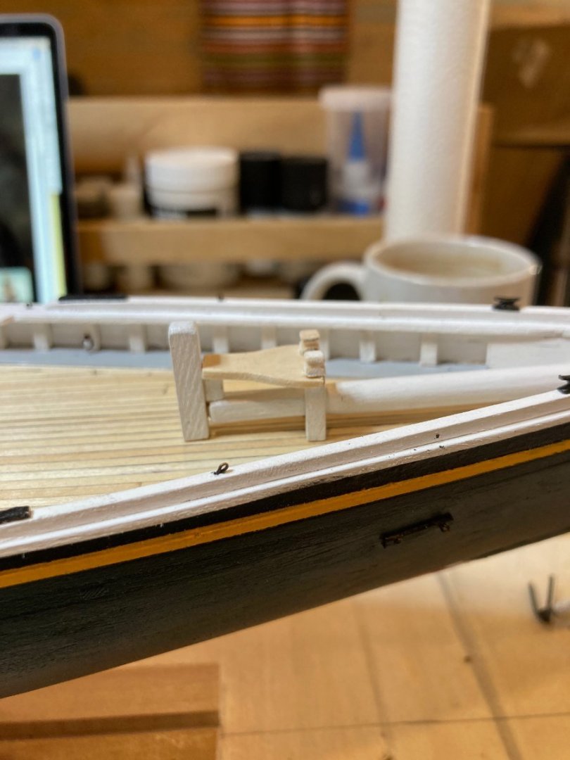
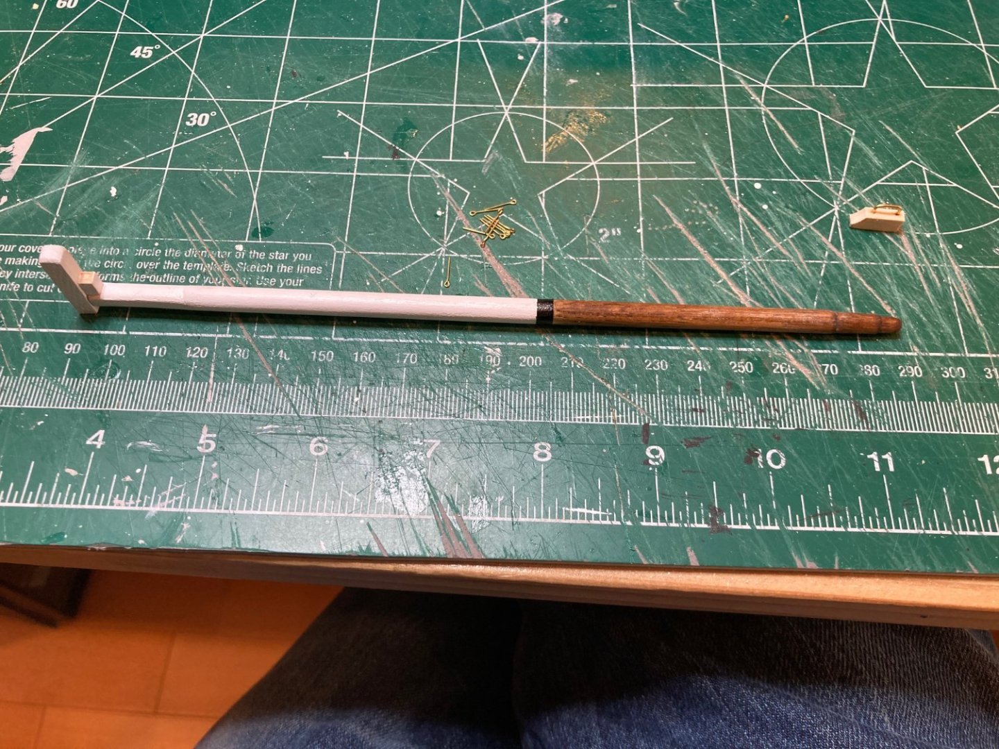
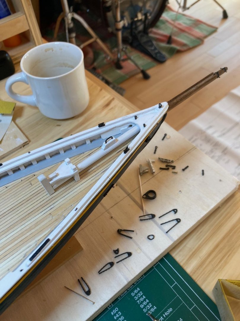
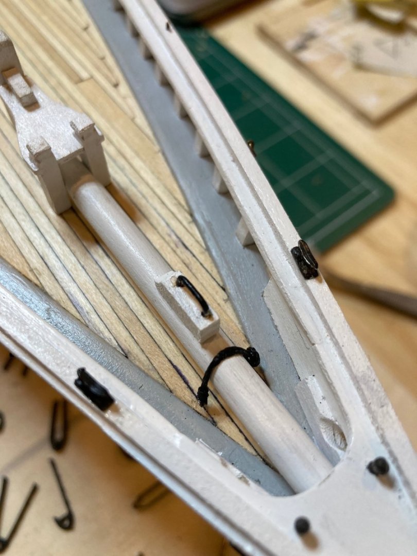
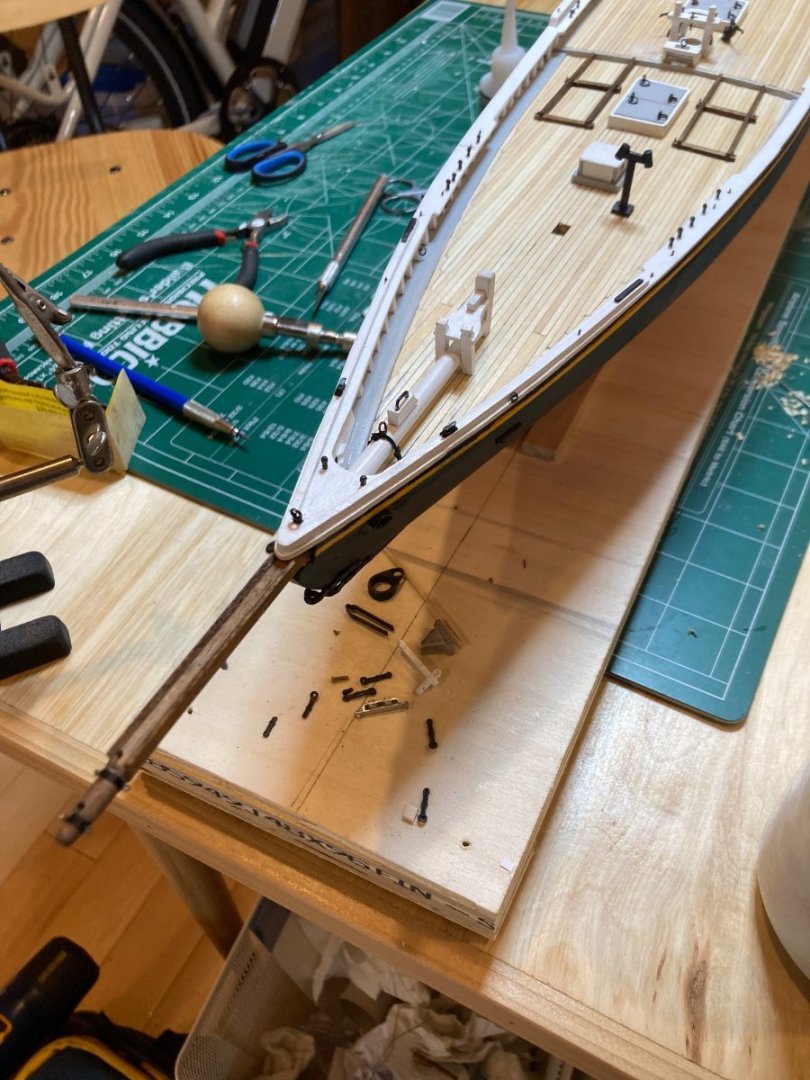
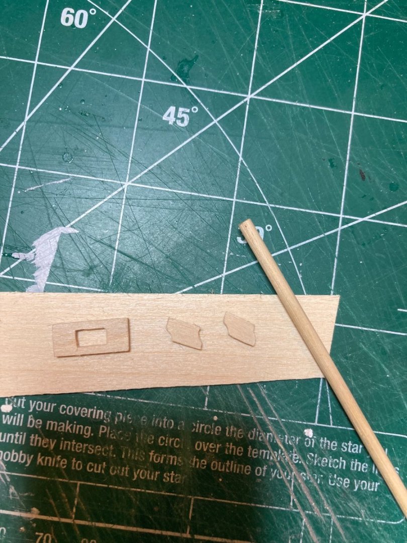
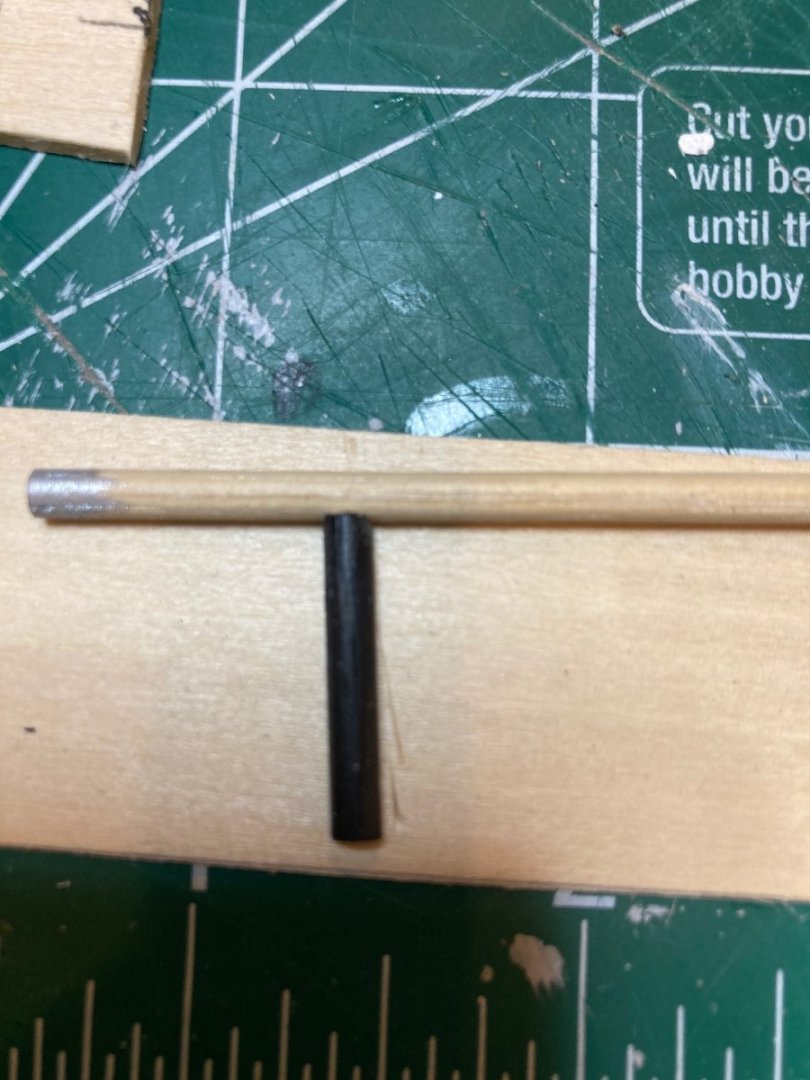
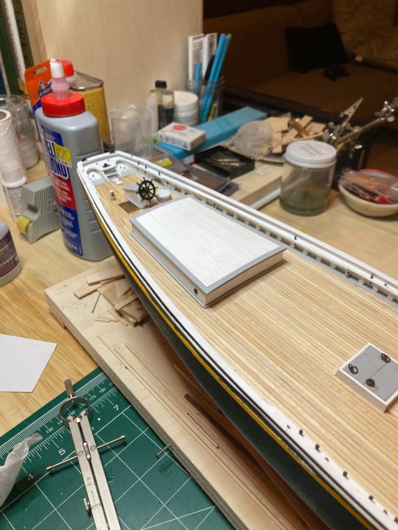
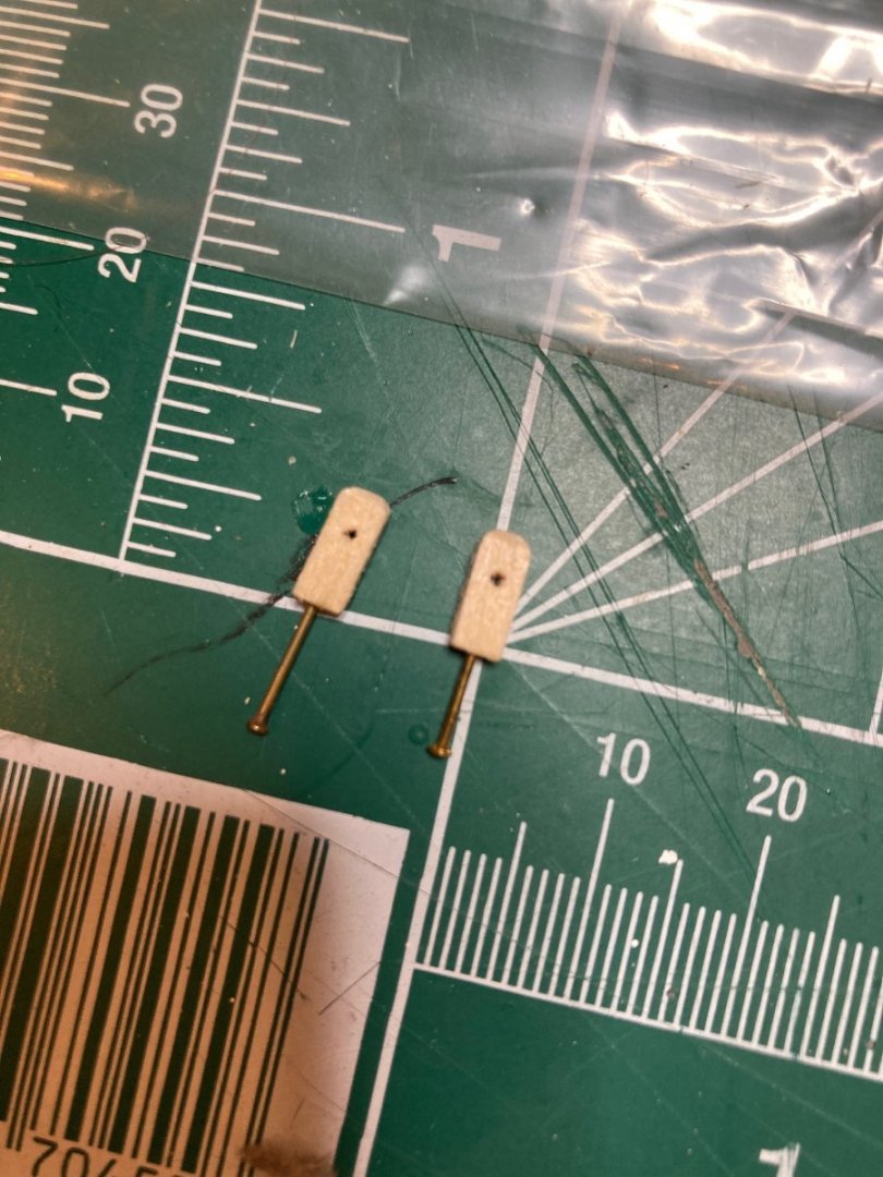
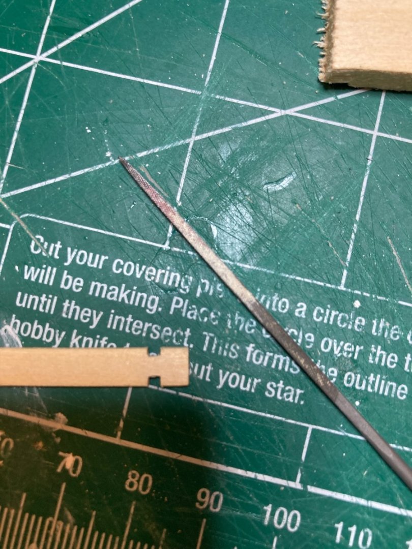
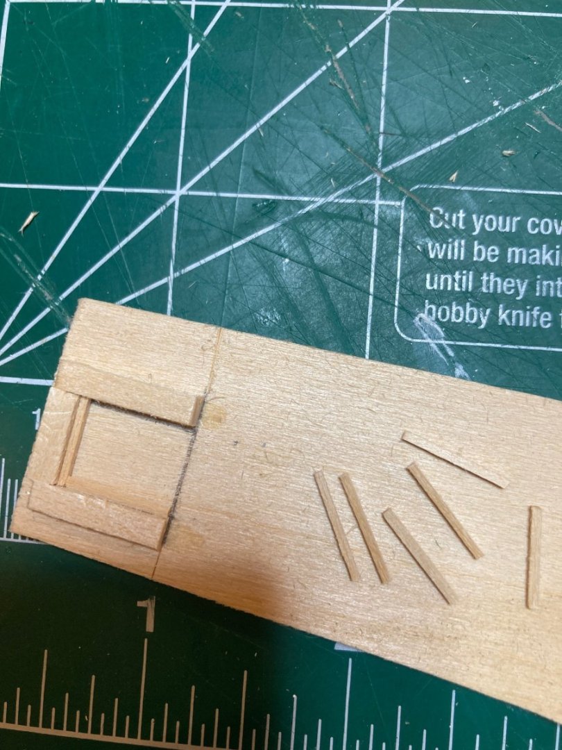
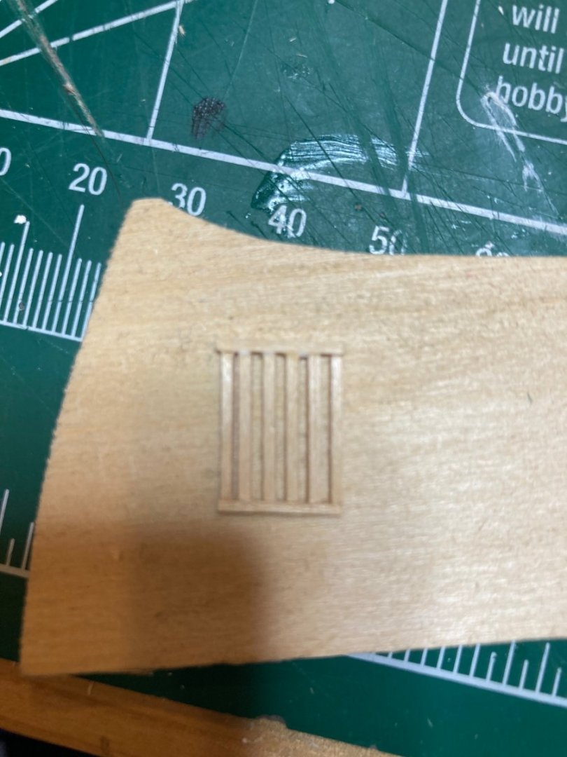
A couple of additions to the Bluenose to report - working on the bowsprit and deck assembly for the samson post & bowsprit bitts. Nothing particularly tricky about these. For the samson post mortice, I drilled through the 3/16" square stock I was using, squared off the hole using needle files and then plugged up the back of it with a 1/8" square bit of basswood. Filed down and painted over it blends in perfectly. The alignment was a bit fiddly, but once the samson post was positioned, things went together more or less easily. Enjoy the photos and happy modelling hamilton


-
Interesting - you may need to use some push pins or straight pins to set the waterway strip in place, since there are no bulkhead extensions. If you start mid-ships and work fore and aft this should be relatively straightforward. It will also give you a chance to test the fairness of the outside edges of the bulkheads - if you tack the waterway strip in place along the tops of the bulkhead edges and get it running in a nice smooth curve, you will see where the bulkhead edges either stick out from or are set back from the outboard edge of the waterway - this will tell you where you need to shave some of the wood off the bulkhead edges or build them up with thin wood strips to get a smooth run of hull planking. hamilton
-
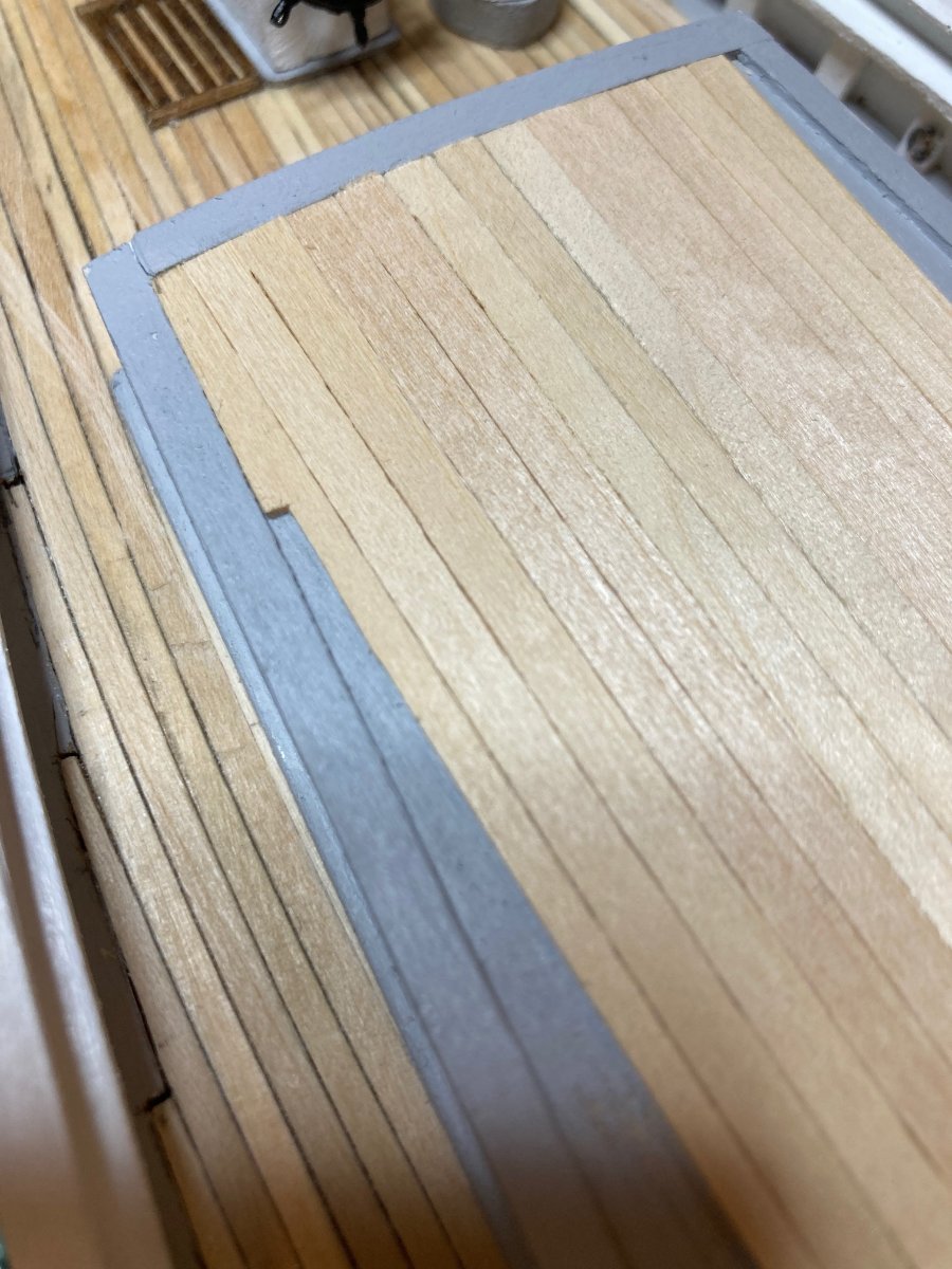
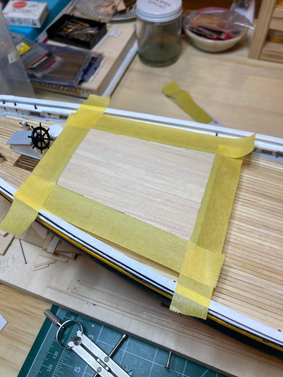
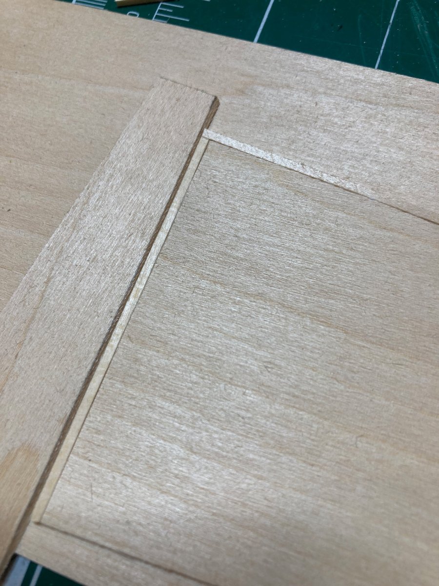
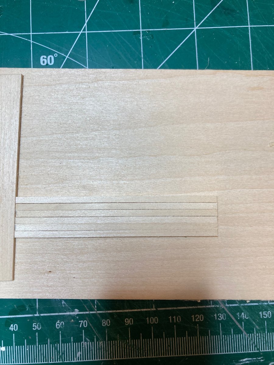
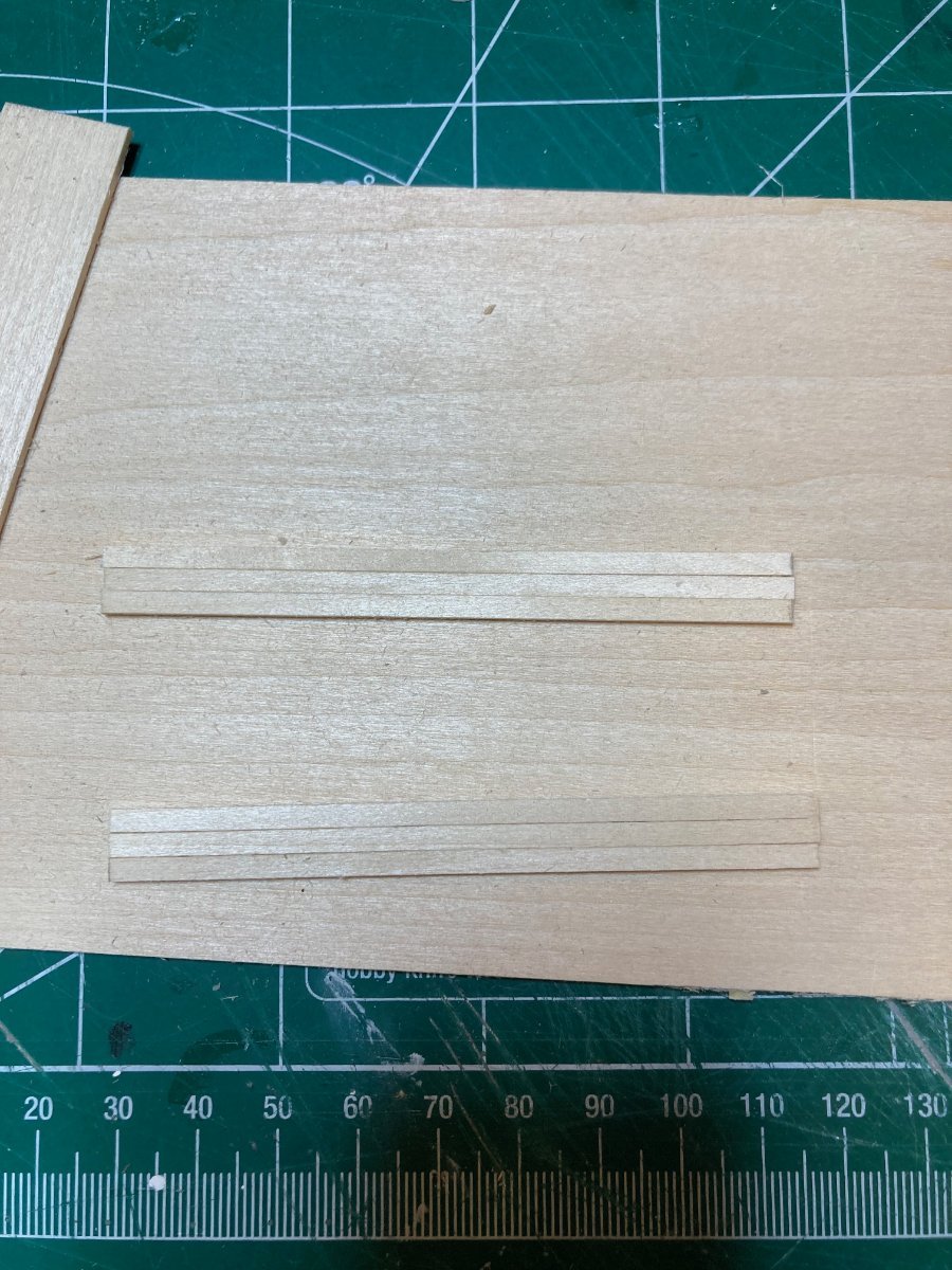
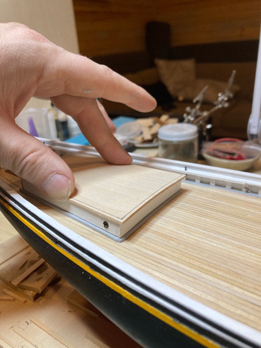
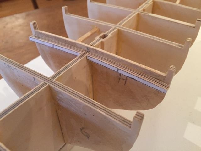
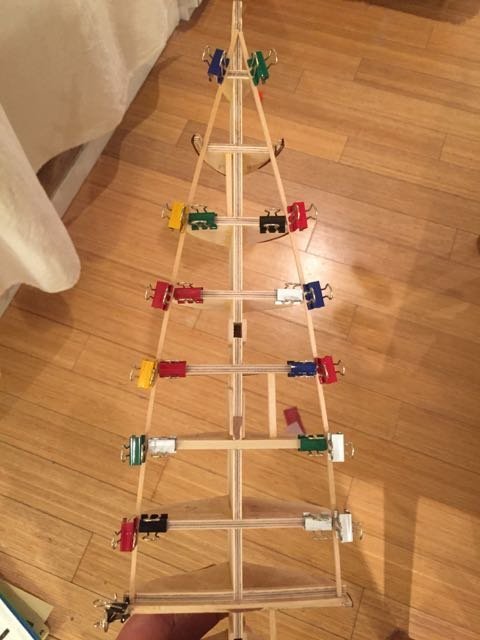
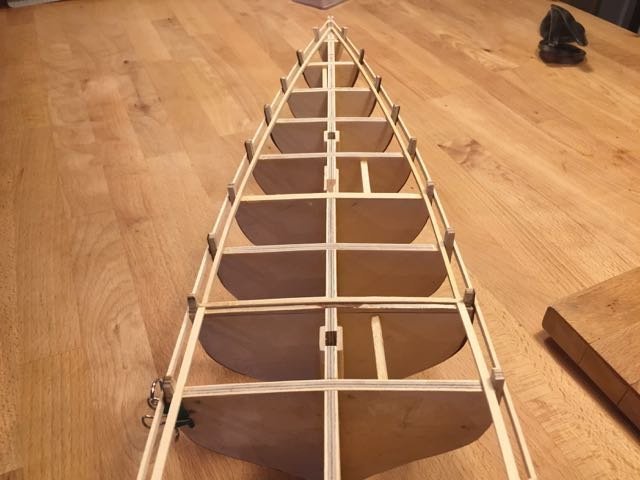
I think you have a good start here. At this stage, I would consider building the stand so the model has something to rest in as you're working on it. After a certain point the model won't be too much "in hand" so it's good to have it in a protected spot. Something to consider before starting the hull planking -- the deck planks on the fore deck need a landing spot for their aft ends, where the step up to the quarterdeck is. I've included below a photo from my current 1:64 Bluenose build that shows this. I just used off-cut scrapwood to do this after tracing the deck "camber" (the curve of the deck from the centreline to port and starboard) onto the forward face of the bulkhead that defines the forward edge of the quarterdeck. If your bulkheads are already glued in it might be a bit tricky to get this line traced. But if not, you can just lay the last fore deck bulkhead and the first quartedeck bulkhead together with their bottoms aligned and trace the top edge of the forward bulkhead onto the aft one - then lay some scrap strips these so the deck plank ends have a place to sit when you come to the decking. The hull planking on this model is actually very straightforward compared with others, due to the overall hull shape. The sharp bow means that there is very little bending and only very slight twisting of the hull planks that needs to be done. Some of the planks will need to be tapered at the bows. You'll be able to tell when to start this as you lay the planks since they will start to want to bend upwards and overlap with the previous one installed - when this happens, just note on the plank the point at which it wants to cross over to overlap with the previous one and taper it gently from that point forward. The first hull plank should be laid with its top edge flush with the top of the deck planking. So it might be easiest to first lay a strip of deck planking along the outside edge of the bulkheads - this will serve to simulate the waterways on deck and give you a reference point for the first strip (or "strake" as we say) of hull planking. Below is a picture of this waterway strip laid on my Bluenose prior to beginning the hull planking - hope it helps to clarify what I'm talking about. The strip is laid on top of the bulkheads and flush with the inboard side of the bulkhead extensions. The third photo shows the waterway deck plank and the first outboard hull plank installed - you can't tell really from the photo, but the hull plank's top edge is flush with the top edge of the waterway plank - the rest of the hull planking just flowed from there. Hope you don't mind me posting these photos in your log. Good luck and keep posting the photos and questions - you'll learn quickly that way! hamilton
-
A unique approach to the stern - looking forward to seeing how it shapes up! The planking looks great so far! hamilton
-
Another quick update while the ham is in the oven. Working still n deck superstructures and features, specifically, the fore boom sheet buffer, the water pumps, the dory frames and the fore deck skylight. All were pretty straightforward, though you'll see in the photos that I initially mispositioned the water pumps - the later photos show them in their proper spot aft of the fife rail. I'll also admit that, because I was not feeling up to the challenge of making the pumps from scratch, I repurposed a couple of pumps that I had in a little drawer of unused parts from other kits...they are not exactly to scale (on the small side), and they are likely somewhat anachronistic in terms of design, but I don't think they look too awful. Here are the photos - enjoy and happy modelling. hamilton


-
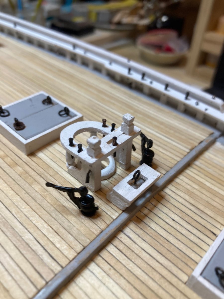
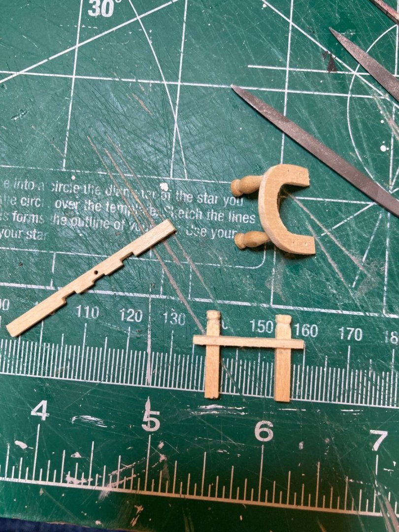
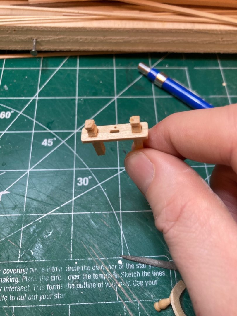
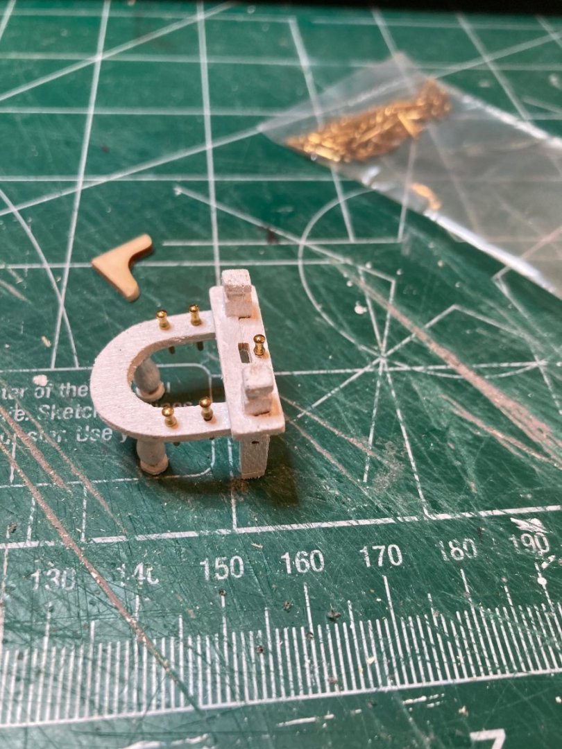
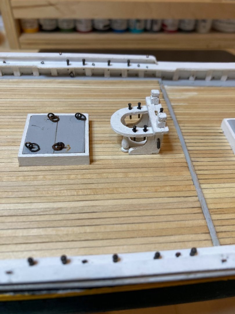
A quick update featuring the main mast fife rail. When I was looking at this on the plans, I figured I could get it done in a few hours - another case of being totally wrong! It took about 10 hours total over three sessions to finish. I cut the pinrack from 1/16" basswood sheet and used a couple of wooden stanchions left over from the Artesania Latina San Francisco which turned out to be perfectly to scale and matched the general shape as well. 1/8" square stock was used for the bitts, and I used two edge-glued 1/8 x 1/16" strips, filed out to accommodate the bitts and the boom crutch, with a small hole drilled for a belaying pin on the forward edge. These were glued up around the posts. Once this was done, I noticed that the two posts were a little out of alignment, so I glued them at the bottom to some 1/32 and 1/8" strip wood to bring them even and to correct height. I repurposed a couple of knees from another kit for the fife rail support knees, as well - these were larger than scale, but were pretty easily trimmed down to size for the bluenose. They are not to scale thickness - being 1/16" when they should be 3/32"....but I glued them close to the outboard edges, so only the very keenest and most attentive eyes will see - and of course all of you who I just told about it!! I also made the mast coat out of 1/8" basswood, drilled and filed out to 5/16" for the mast. The belaying pins were blackened (looking a little hairy) to complete the little project. I am starting to get really concerned about all the metal work that's coming up with the masting and forward deck details. I have very limited experience working with metal and given that my blackening technique also produces pretty fuzzy results....I will have to do a bit of practice with the soldering gun and see if I can't wrap my head around it....Definitely going to fudge as much with wood as I can get away with, but at a certain point I feel like it's hard to model without picking up some metal working chops..... Until then, though, it'll be more deck superstructures. Enjoy the photos and happy modelling hamilton


-
Thanks Andy - that is an approach I have never heard of before - something to consider experimenting with on Bellona when I come back to that build later in the spring. And thanks Alistair - that's high praise coming from you - you were there almost at the very beginning of my modelling "career" way back in our AVS days, so you've got a lot of context! Not to wax too nostalgic, but that has been one of the effects of the pandemic on me it seems..... hamilton
-
Thanks a lot Greg! And thanks even more for pushing this log onto page 7! I think using soft plastic would not work - but you could either grab some acetate transparencies from your local office supply store or use any firmer but thin transparent plastic you have lying around to simulate this. I have used transparencies in the past to simulate glass on ship models, though I also made the mistake of fixing them with crazy glue, which produces a weird crystalising effect on them....I'm not sure what adhesive others would recommend to achieve this effect, but maybe there is some info elsewhere on the forum on how to do this..... Thanks again for stopping by! hamilton
-
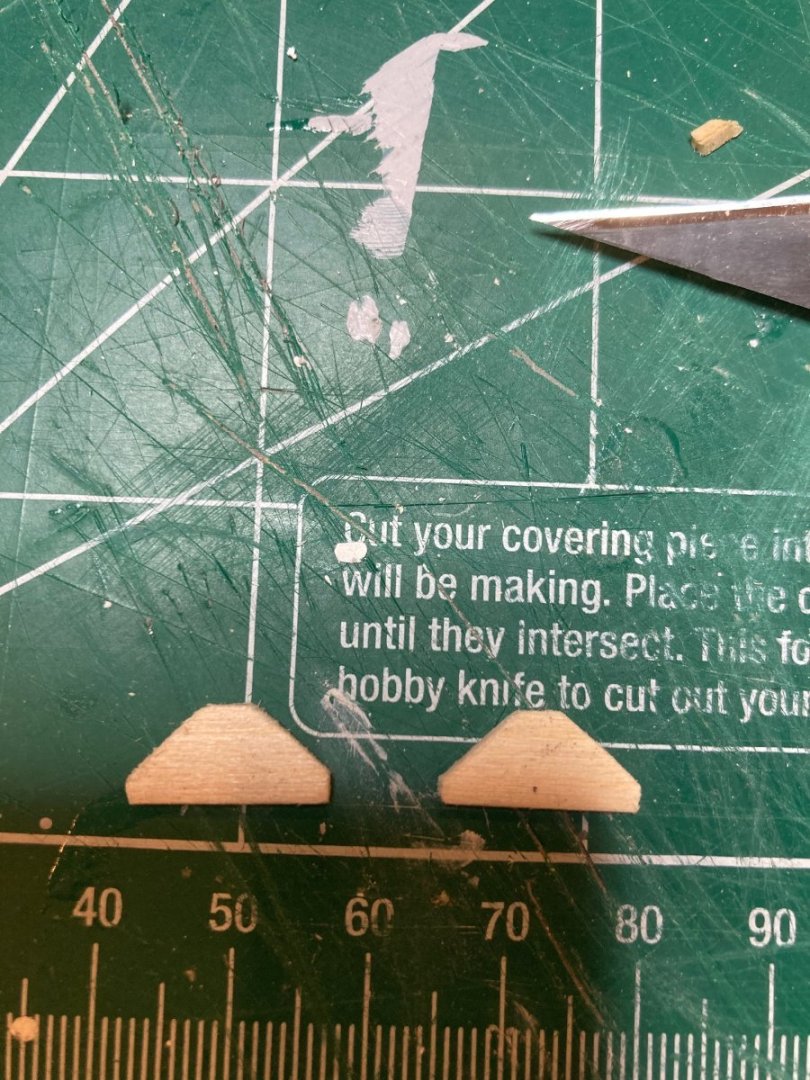
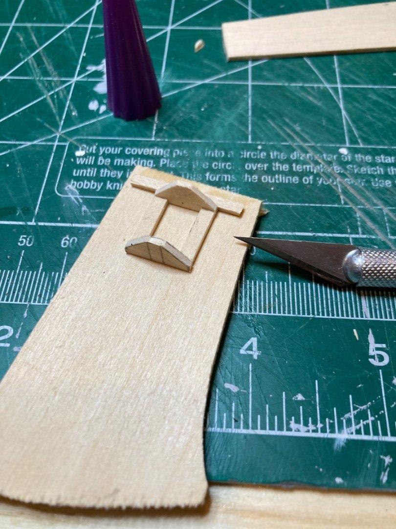
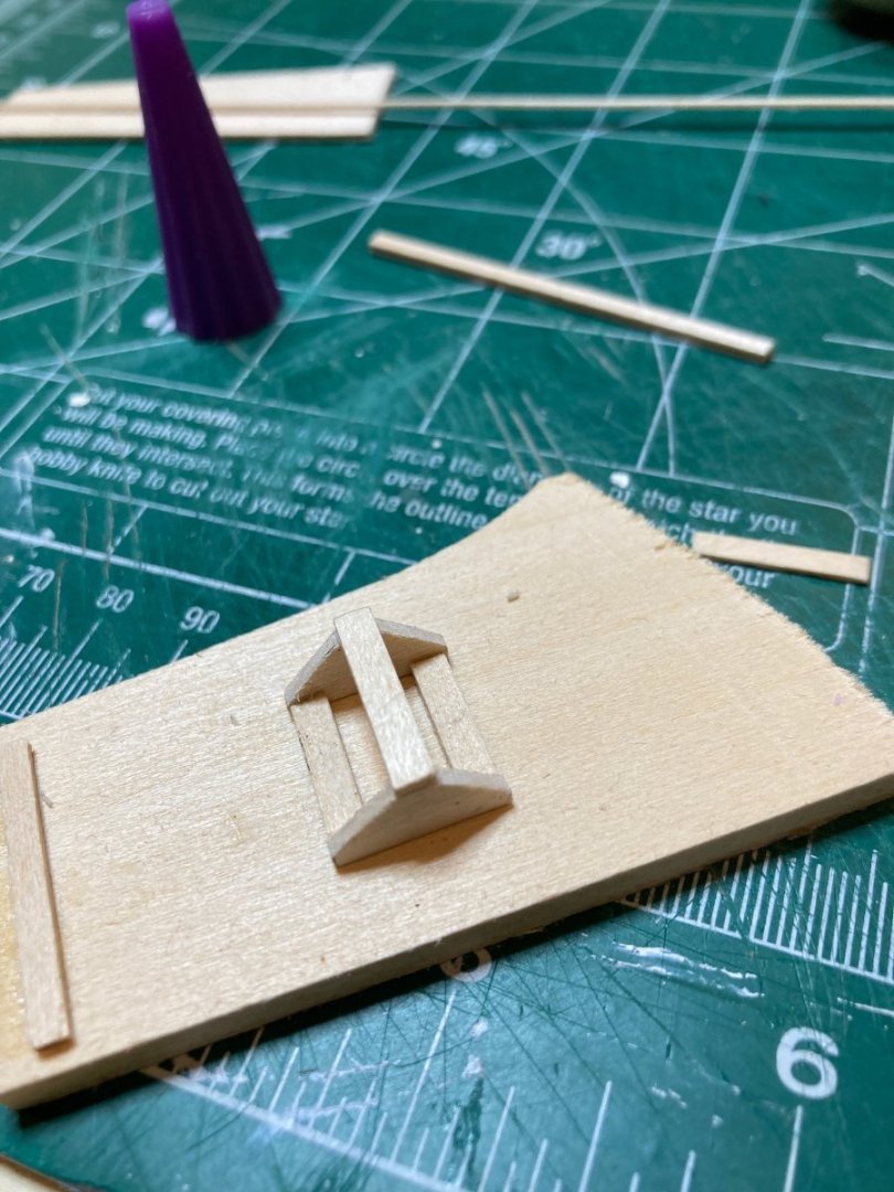
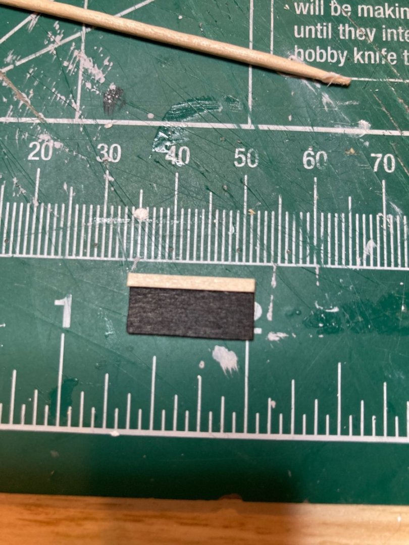
Well it looks like what I thought was going to be a serious work crunch is not going to be as crunchy as I thought!! That's good news in itself, but it also means I've been able to keep at Bluenose over the last few days. I've now completed the cabin and made a start on the fife rail. The last part of the cabin to complete was the skylight, which I had a previously constructed version of from my first go at the cabin - but this was do wretched that I knew I had to at least try to improve on it - I think the new one is a definite improvement, even if it isn't perfect. I am still waffling about adding brass rods to the skylights as shown on the plans, but I feel like this can be done at any time between now and the rigging so I'm going to give some thought to it. I used 1/16" basswood sheeting to craft the triangular ends of the skylight, and connected these with 1/8 x 1/16" strip. These were glued up and another 1/8 x 1/16" strip was used at the peak. The lights themselves were made from 1/32" basswood sheeting, cut to measure and finished black. 1/16" x 1/32" strip wood was finished white and then installed around the edges of 1/32" sheeting for the skylight frames. Once these were added, I used small sanding blocks to refine the edges and added little bits of pinstrip tape to simulate hinges. The photos below show the process and the results, with the old skylight in one shot for comparison. Happy modelling to all and enjoy the photos hamilton
-
Thanks Jason! The model's progressing, yes! But this log can't seem to get off page 6!! Sorry if this is becoming an unwelcome obsession of mine.... hamilton
-
Hi Knocklouder - I think your work looks great! - mine was not up to that standard after only 2 years in the hobby - or even after 14!! I think that as long as we're learning (which is always), we should give ourselves some latitude in terms of both the aesthetic qualities of our results and their relative historical accuracy - but tbh I don't think you have anything to worry about on the aesthetic end. As for historical accuracy, if you're not being commissioned by a museum to represent this or that ship at this or that stage of her career, then you're really under no obligation other than what you decide for yourself. Then it's more about the (sometimes masochistic, as in ratlines) pleasures of the process and developing your craft. hamilton
-
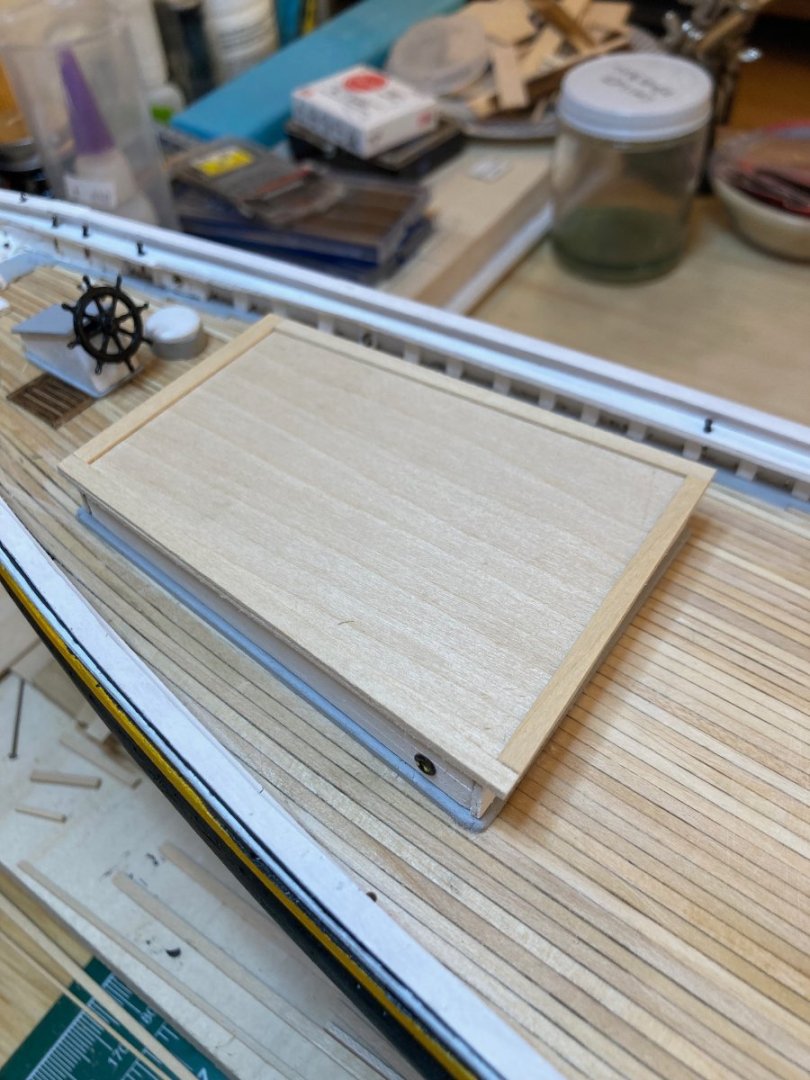
Alright - this is turning into page 6...66!! I haven't done this much scrolling on a web page since 1997! Making me nostalgic for Ask Jeeves, AOL and Netscape Navigator! In any case, though I mentioned taking a break I did manage to squeeze in a bit of time at the bench over the last couple of days to work on the cabin - specifically the roof. I had already cut a base for the roof out of a basswood sheet. I then added some 1/32" x 1/8" strips around the edge as a border (finished grey), before planking the interior surface with the same material, finished white. The cabin is already installed on deck, so once I installed the trim, I just added the roof and planked it in situ (learned a lot of Latin in the 90s, too, because I was thinking of my future, obviously!). I think it turned out pretty ok. Here are the photos. I'm going to actively try to stay away from the bench now for a bit! No promises, though.... Enjoy hamilton


-
Looking good, Steve I have used Blacken-it, as Knocklouder recommends, but can I ask you, Knocklouder, can you get that in Manitoba? My local hobby store owner here in Vancouver said that it was no longer available for import to Canada - were they just blowing smoke?....clearly you have a line....I like this product way more than what I'm using now, and would love to get my hands on some.... hamilton
-
Hi Gregg Your Bluenose looks great! I have a more labour intensive, but perhaps also more satisfying solution - at least if I understand your issue correctly. If you can access some 1/16" basswood sheets at a local hobby or craft store I would recommend grabbing one and using that to make the rails. You can make the forward and stern parts by making templates from the plans You can then modify these templates to suit the model as built and then use the modified template to cut out the parts from the basswood sheet. The main parts of the rails can be made by laying the sheet along the bulwarks and tracing the hull curve onto it from below. Cut out this tracing and then use a protractor to mark out the width - don't forget mark out where the pin rail and cathead extensions are before cutting it out. I did this for my scratch Bluenose and it worked fine hamilton
-
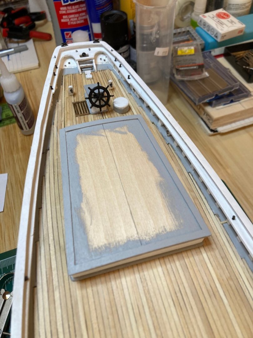
One last update before the end of the weekend. I started working on remaking the main cabin. I managed to salvage some elements from the old one, but will need to remake the cabin itself, including the companionway. I first took a tracing of the cabin dimensions from the plan and transferred this to a sheet of 1/16" basswood. After cutting this out and refining it a bit, I added some 1/16 square stock around the edges as a coaming. The outside edges of these were rounded over slightly and finished grey. The sides were built up out of 1/8 x 1/16" strips. The fore and aft sides were shaped according to the deck camber and all four sides were finished white. I added a couple of grommets, blackened, as portholes and then assembled these on top of the base with the coamings. In the photo that shows the cabin you'll see that the grommet is misaligned on the starboard side - it should be forward instead of aft - but these piece are dry fit only in that photo, so please be assured that the sides are installed correctly as of now. The roof was made in a similar fashion as the base but I did not have time to do much more than cut it out - and that was as far as got today. I'm going to take a short break from Bluenose for the next few weeks as things are stepping up at work and I will have very little time at the bench. So it's a brief farewell for now - hope to be back in April with more progress here. In the meantime, enjoy! hamilton


-
Thanks Nearshore and Greg! hamilton
-
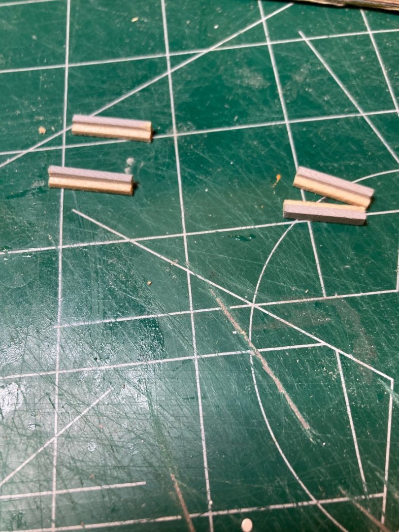
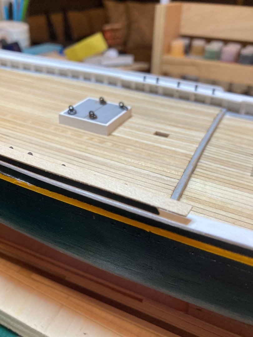
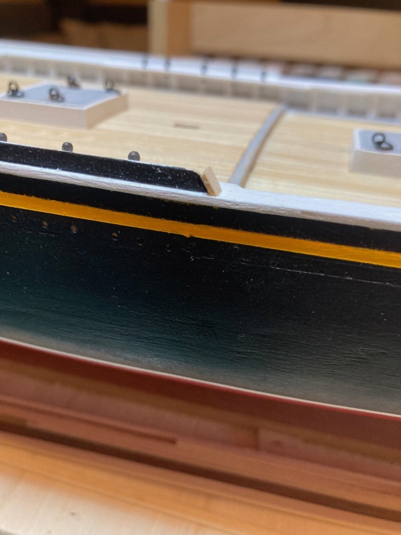
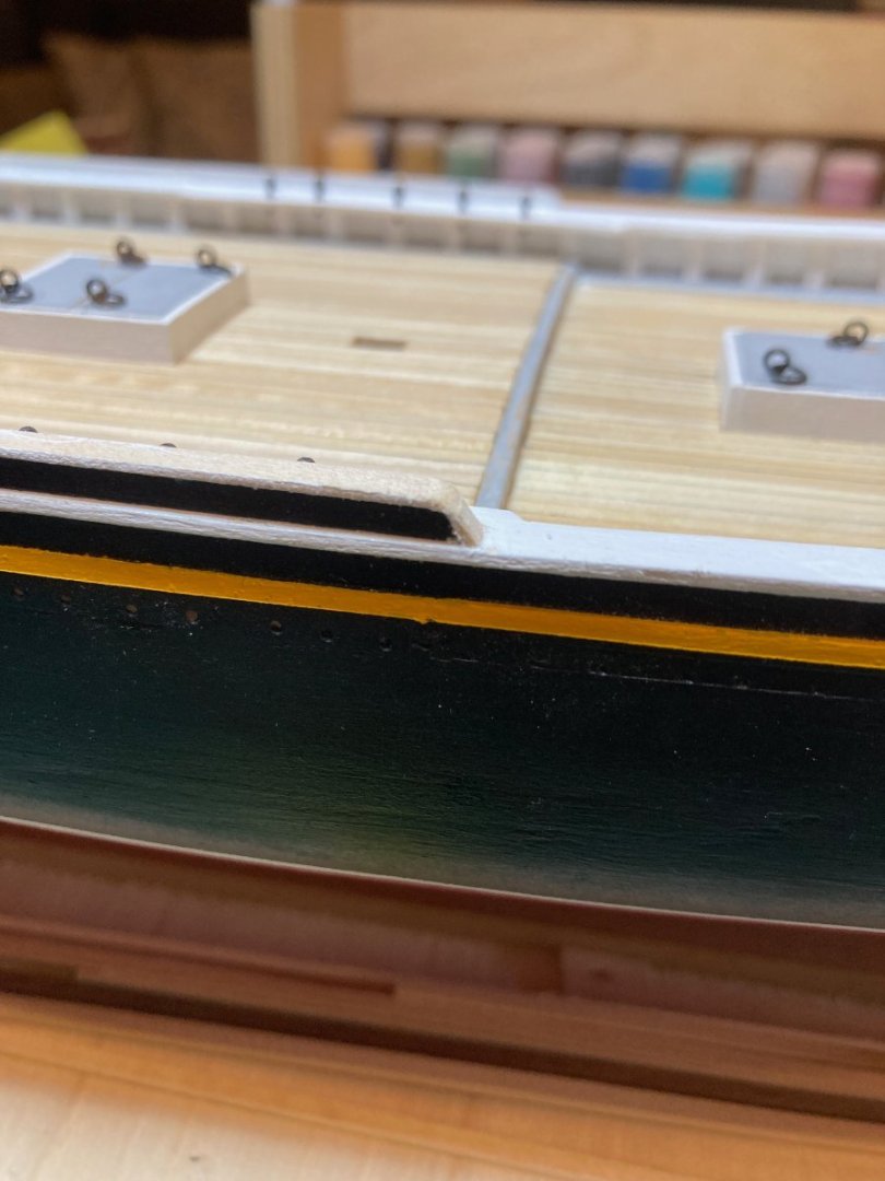
Hello there I really hope this post pushed the log over to a new page - this scrolling is painful! In any case a small update documenting stern deck details - the main boom sheet horse, the main boom crutch pad, battens beside the wheelhouse to starboard and the "unidentified object" beside the wheel house to port, as well as two bollards. Not much to say about these bits - hopefully the photos will explain. The cabin you see in the last photo is the one I made a while back and that I will re-do as it turned out slightly asymmetrical the first time - hoping to salvage some of the parts for the rebuild, but..... And now....lunch!! Enjoy hamilton


-
HMS Euryalus 1803 by rlb - 1:48 scale
hamilton replied to rlb's topic in - Build logs for subjects built 1801 - 1850
Wow! Amazing work with the chisels, Ron! hamilton- 122 replies
-
- 3
-

-
- Euryalus
- Plank-on-frame
- (and 4 more)
-
I would also suggest that, at 1:100 scale the area beneath and immediately aft of the forecastle will get extremely crowded and any extension of the bulkhead will compound that situation - though I'm still a little vague on what you have in mind for the "curve"....in any case, it might pay to make a scale drawing with the deck elements included to see what kind of ramifying effects a structural change will produce. Everything in ship construction relates to something else, so any adjustment is going to affect those relationships - and since the maximization of the efficient and effective use of space is probably one of if not the main construction principle in maritime architecture and design, the smallest change can have a significant effect on the overall arrangements. Regardless - the model is looking good! hamilton
-
Hi Srenner: The build is really shaping up! You mention a "curved" bulkhead above - do you mean curved along the top and bottom edges to match the deck camber? Or curved convex or concave on the fore/aft plane? I think that period practice would argue against the latter, though as in all things the aesthetic choices of the modeller are their own! Adherence to historical accuracy - especially in a kit like this one that has soooo many complications in it - is always tricky with a kit and ultimately it's about what is satisfying to you. Anyway, looking forward to seeing more progress. hamilton
-
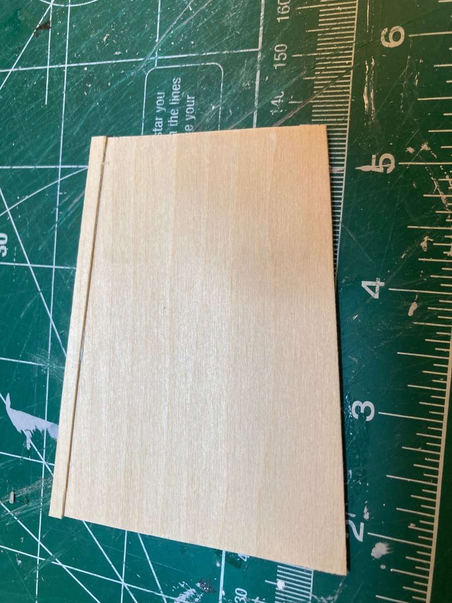
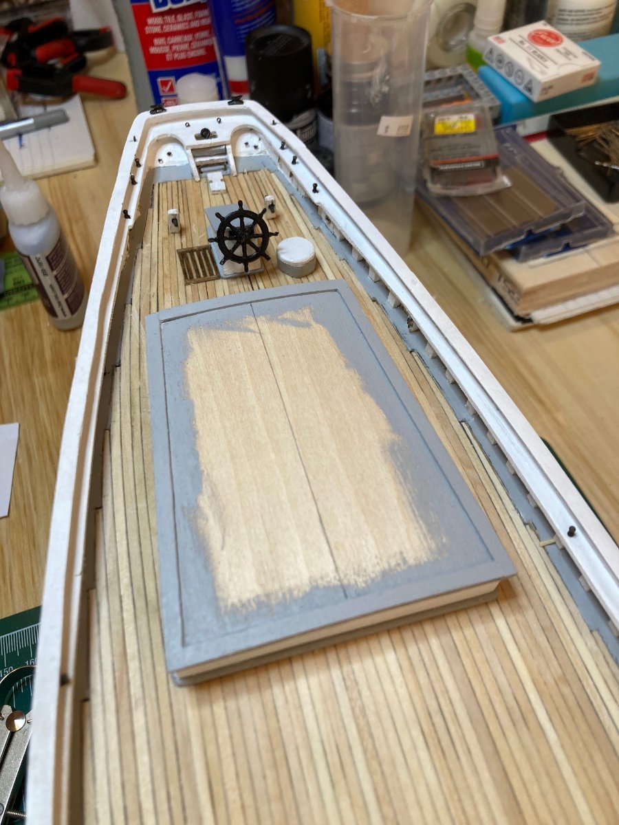
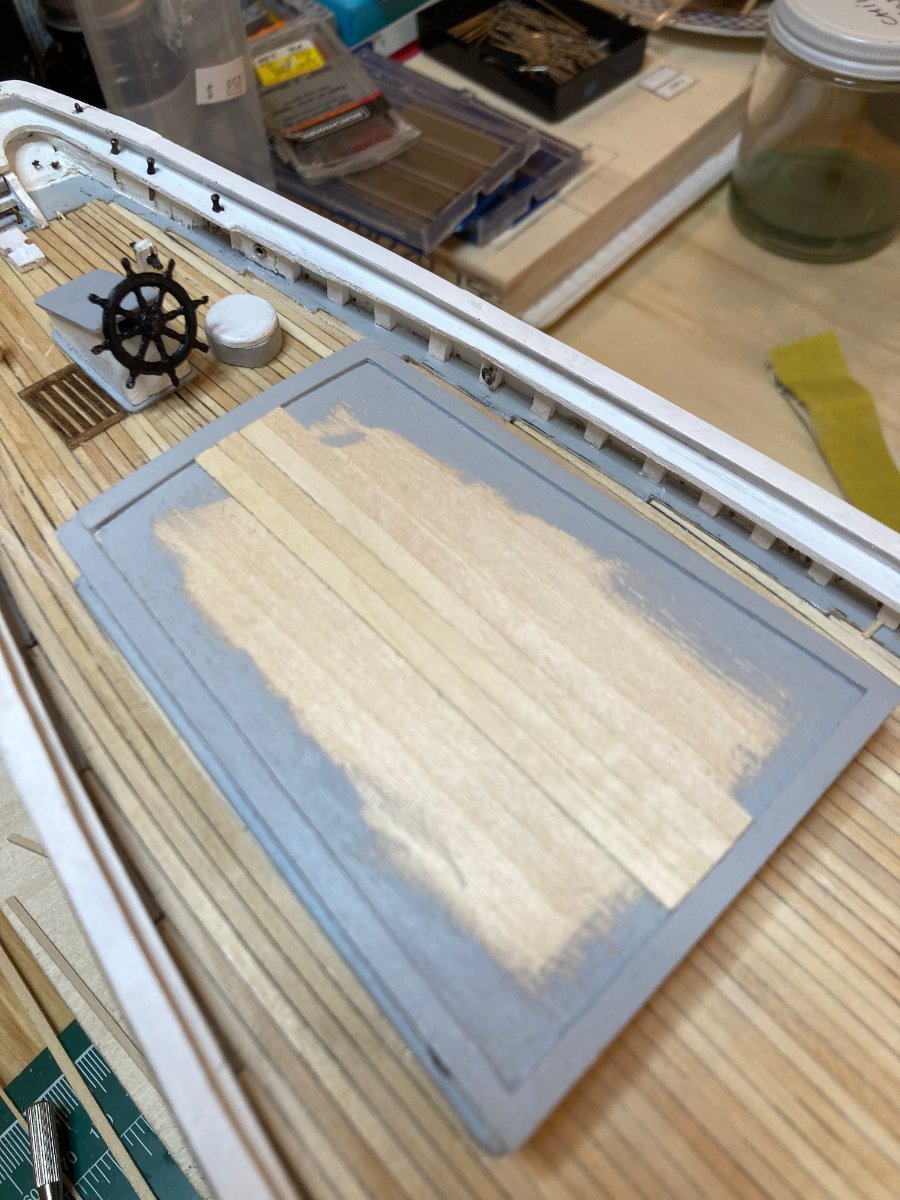
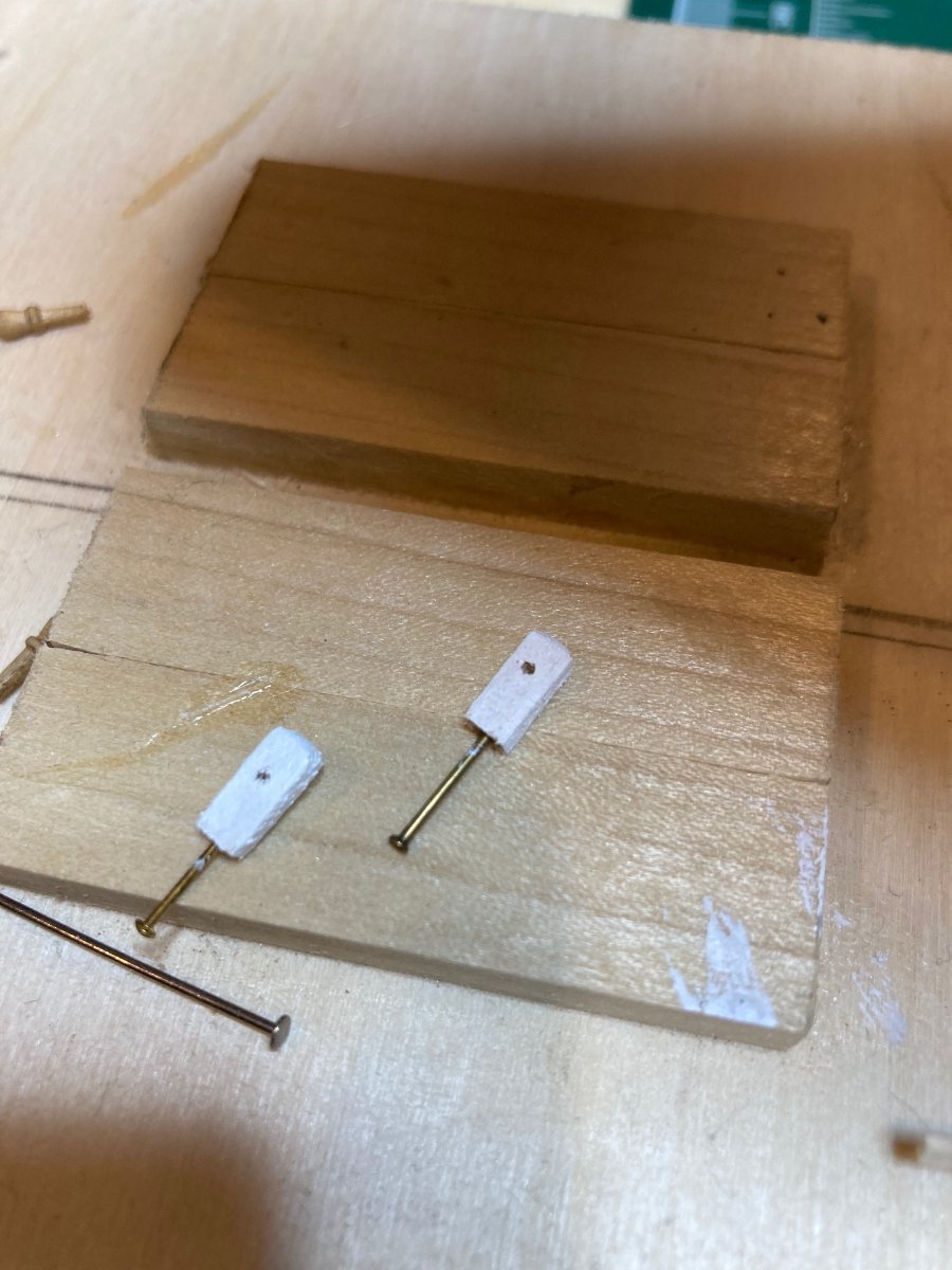
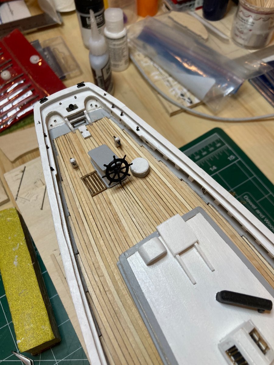
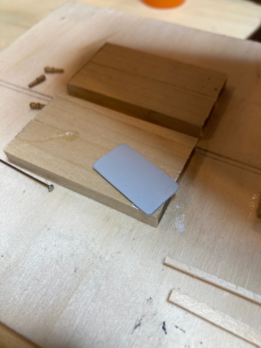
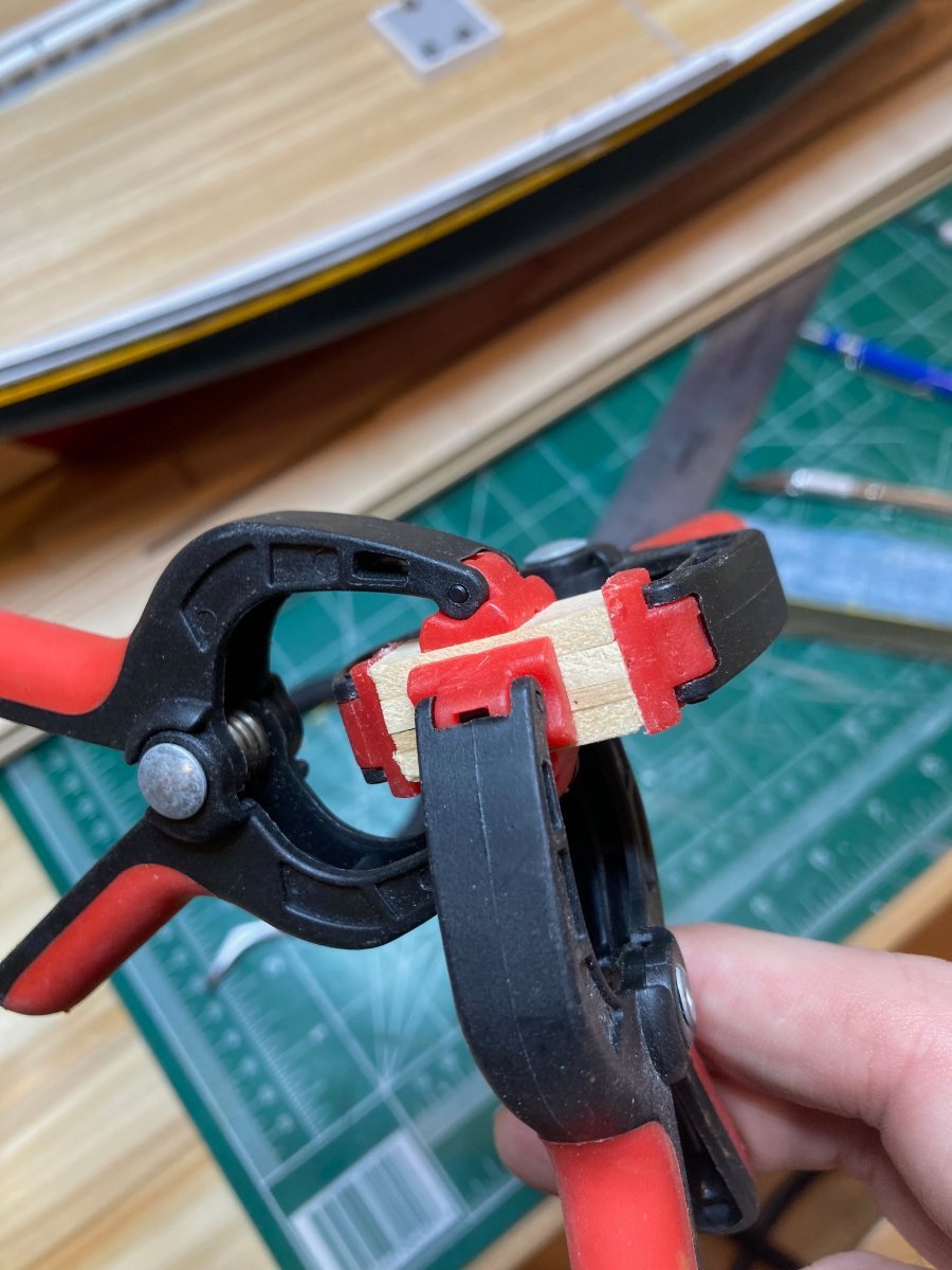
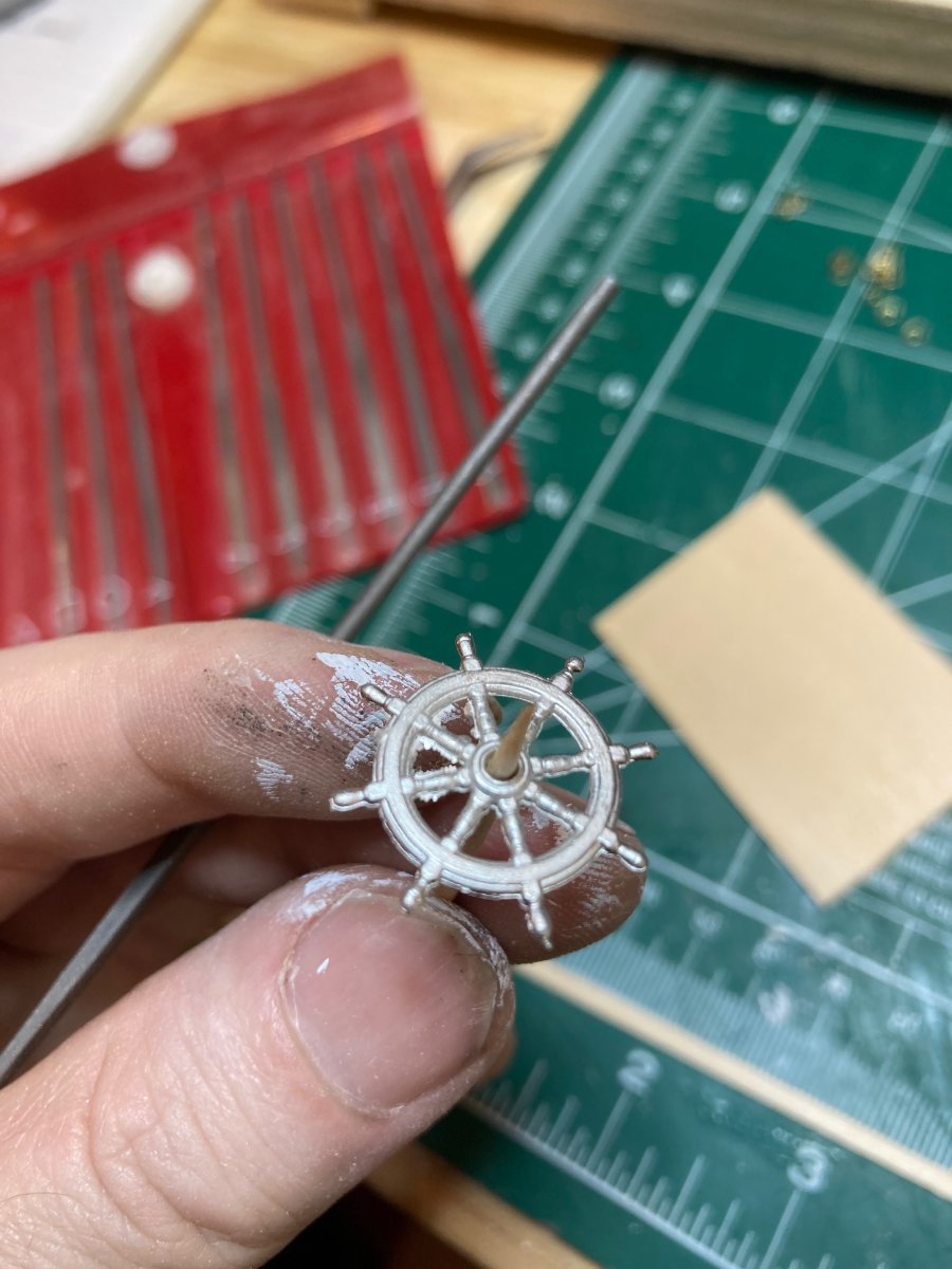
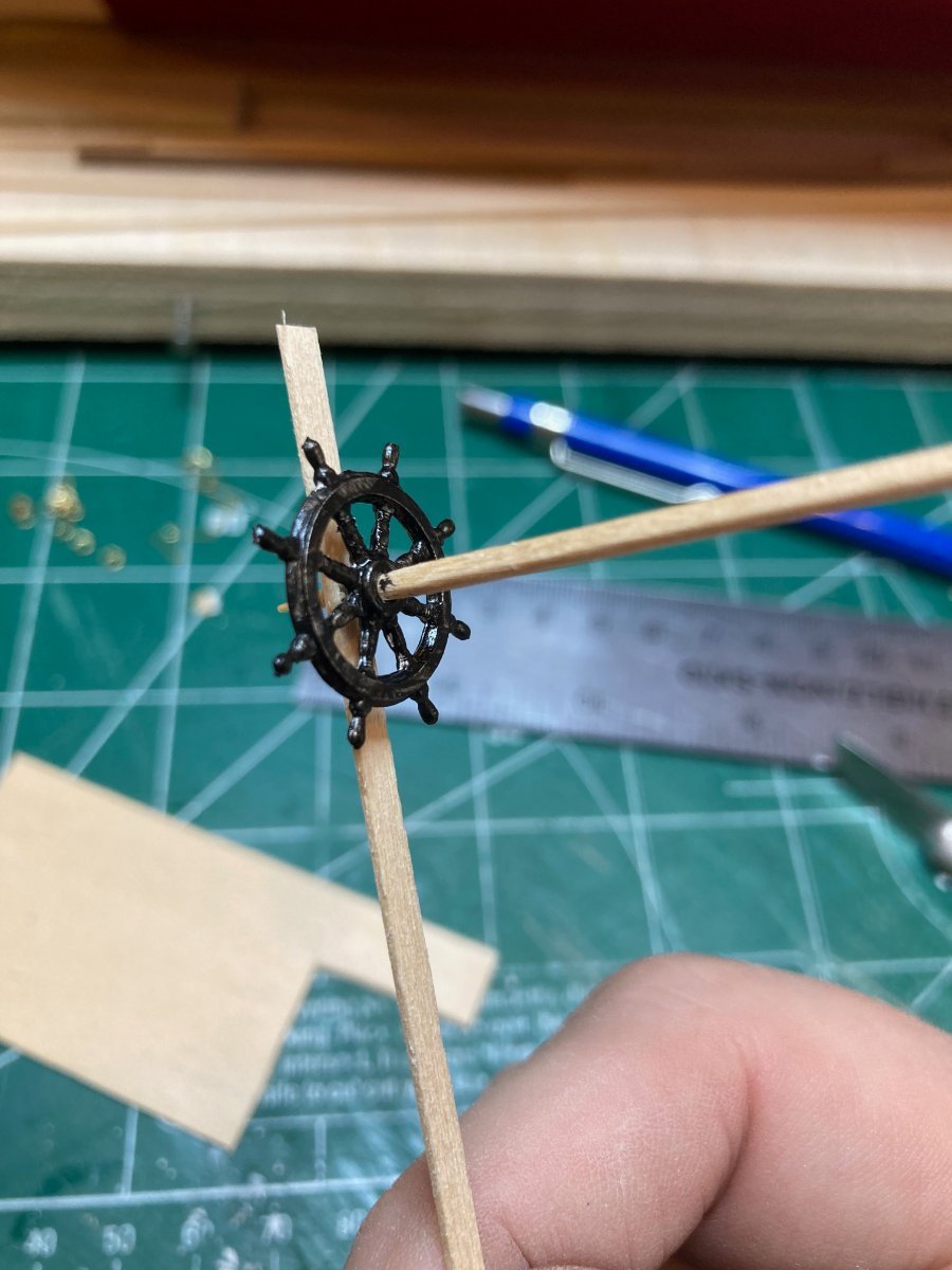
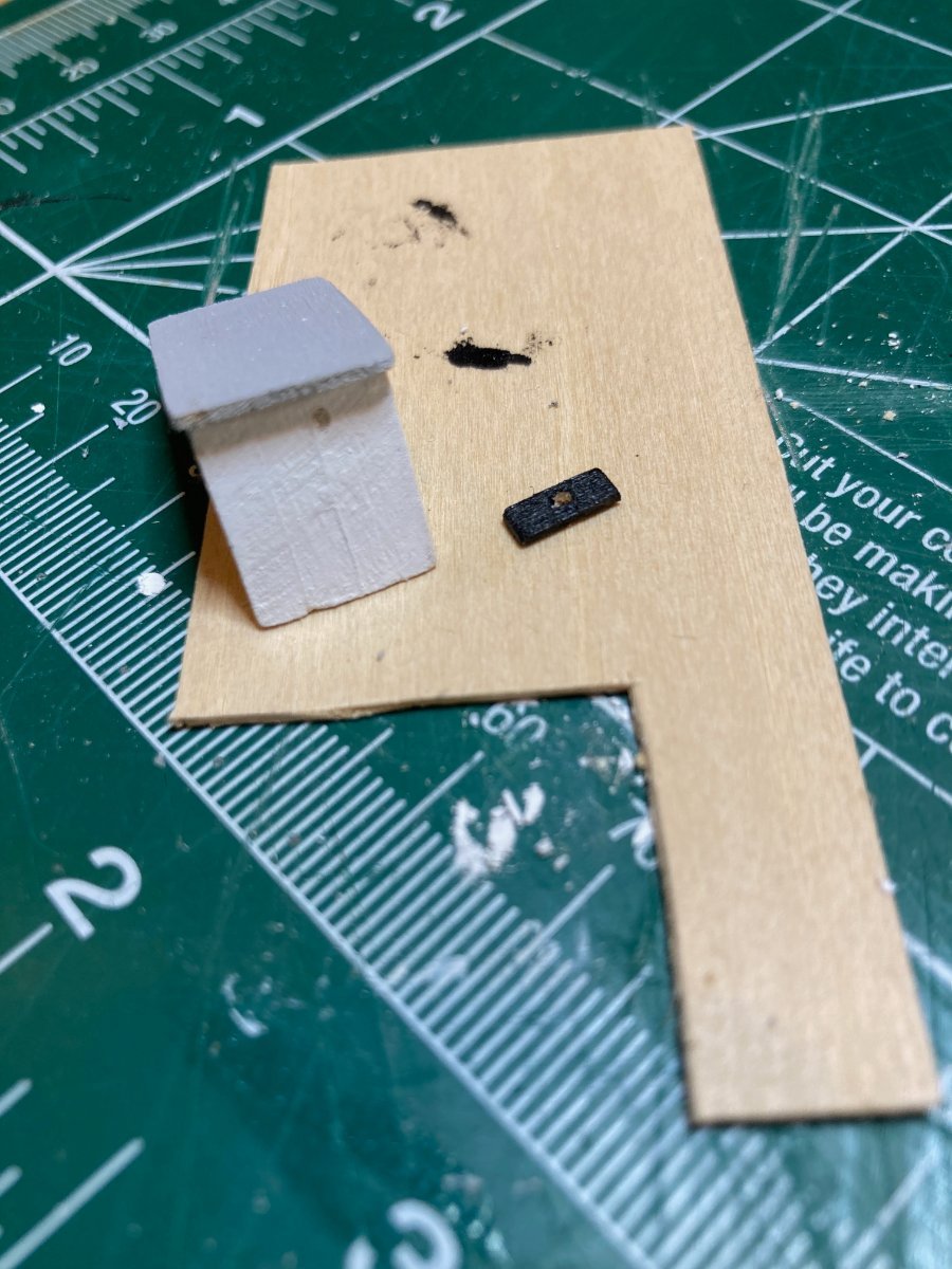
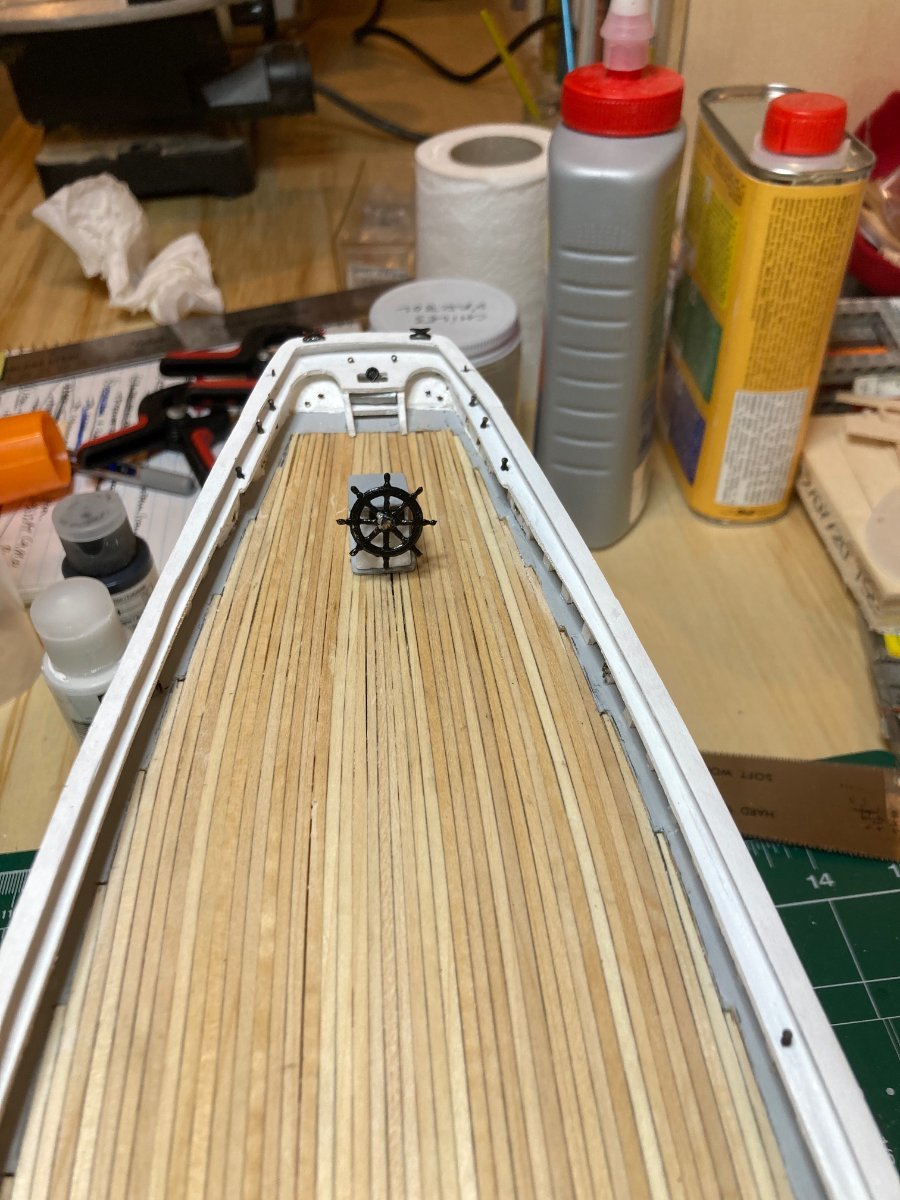
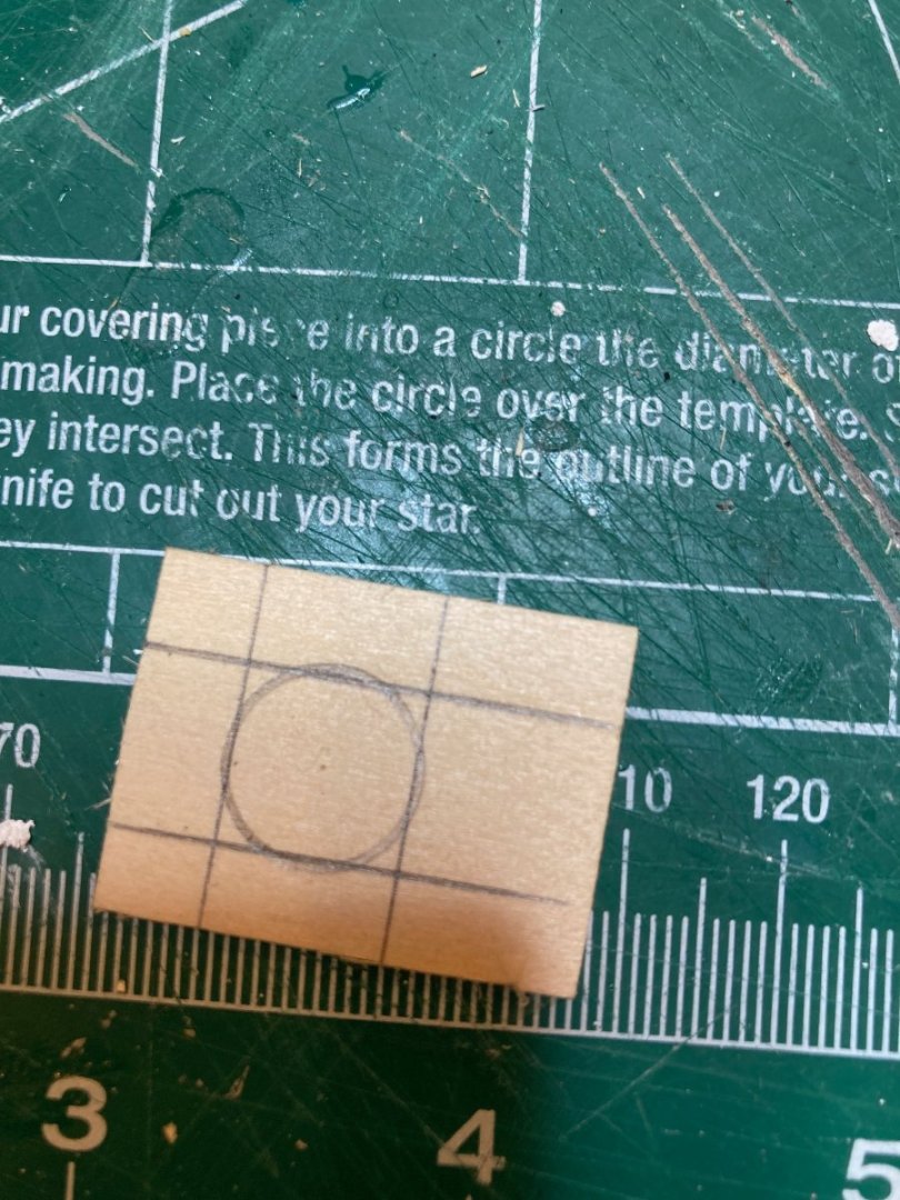
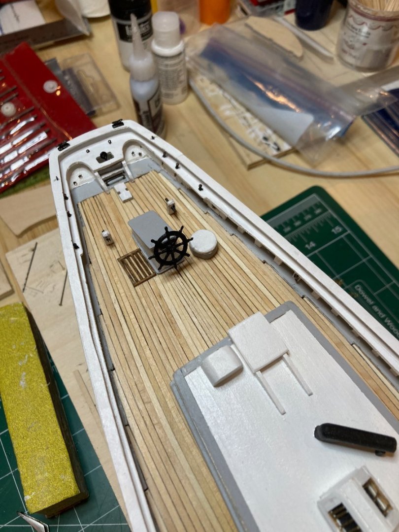
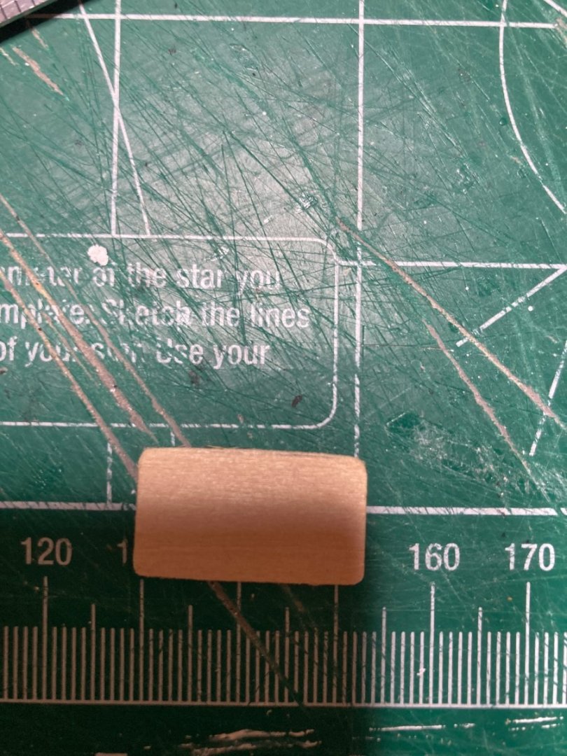
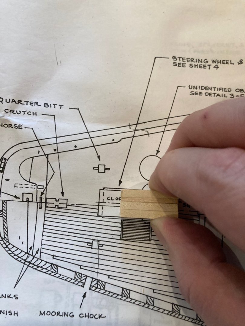
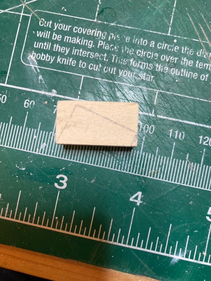
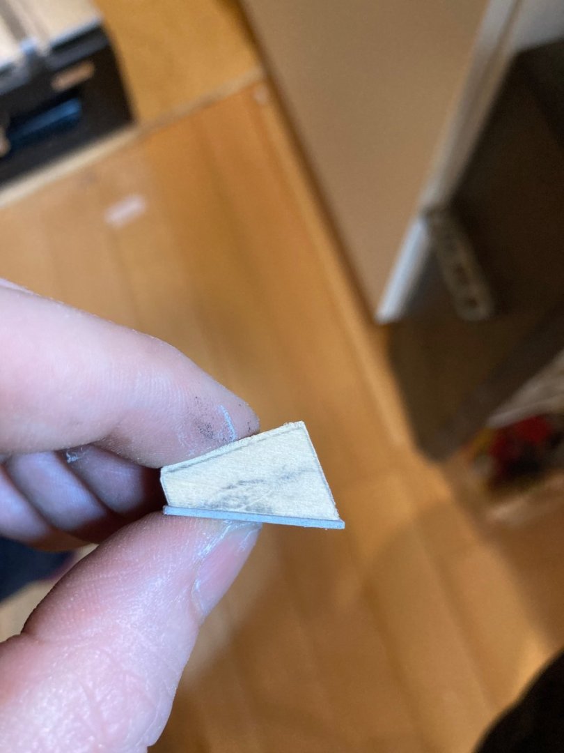
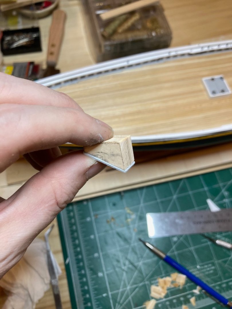
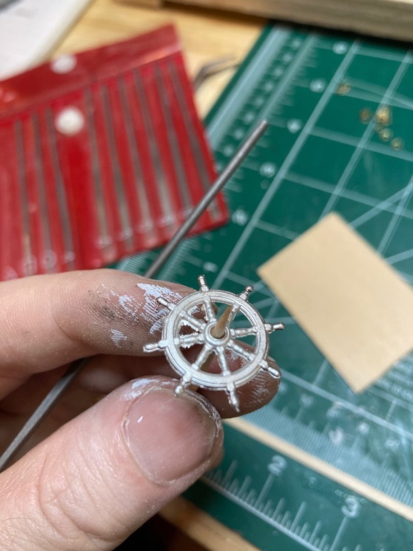
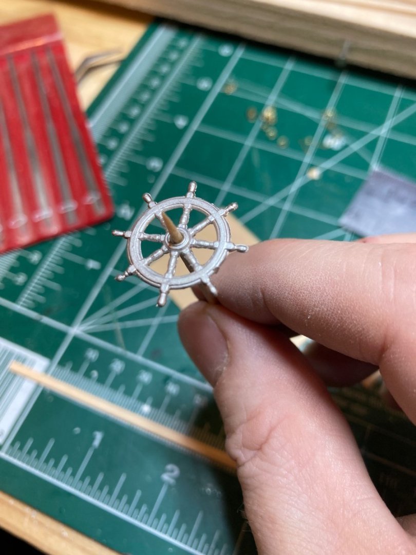
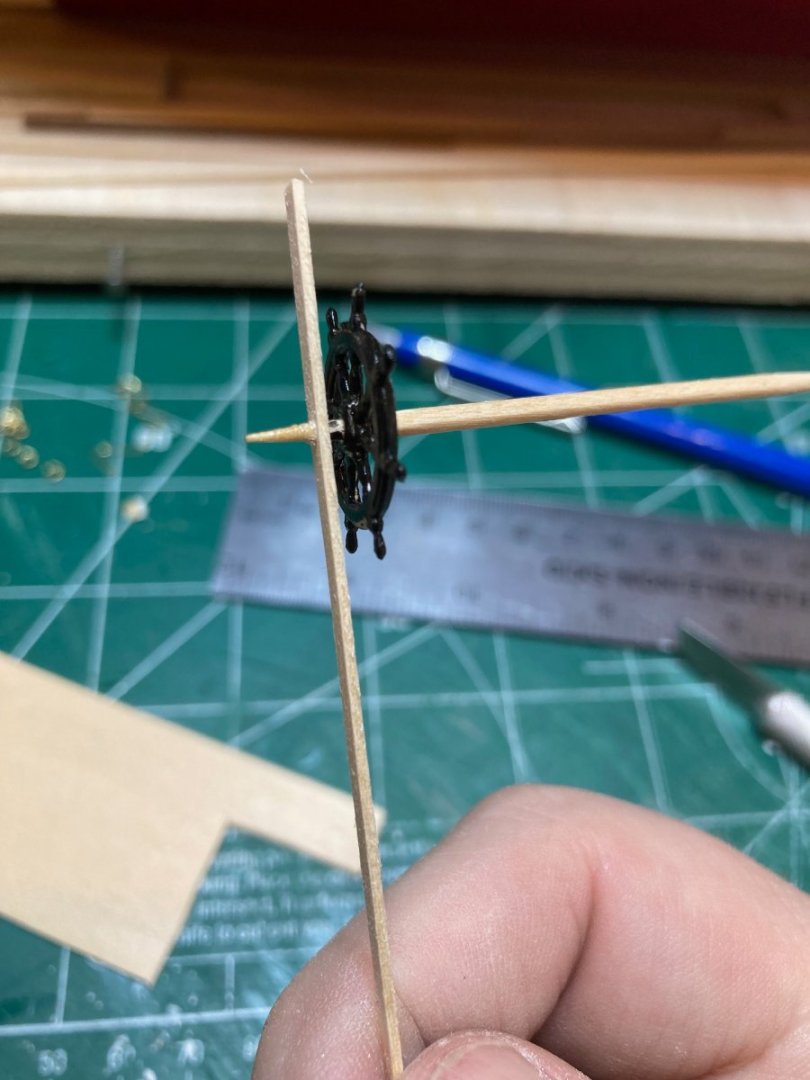
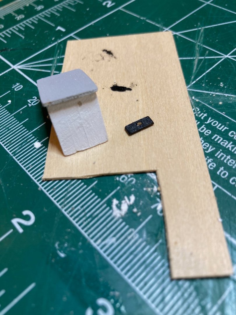
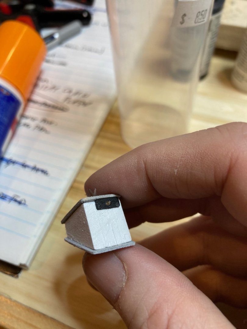
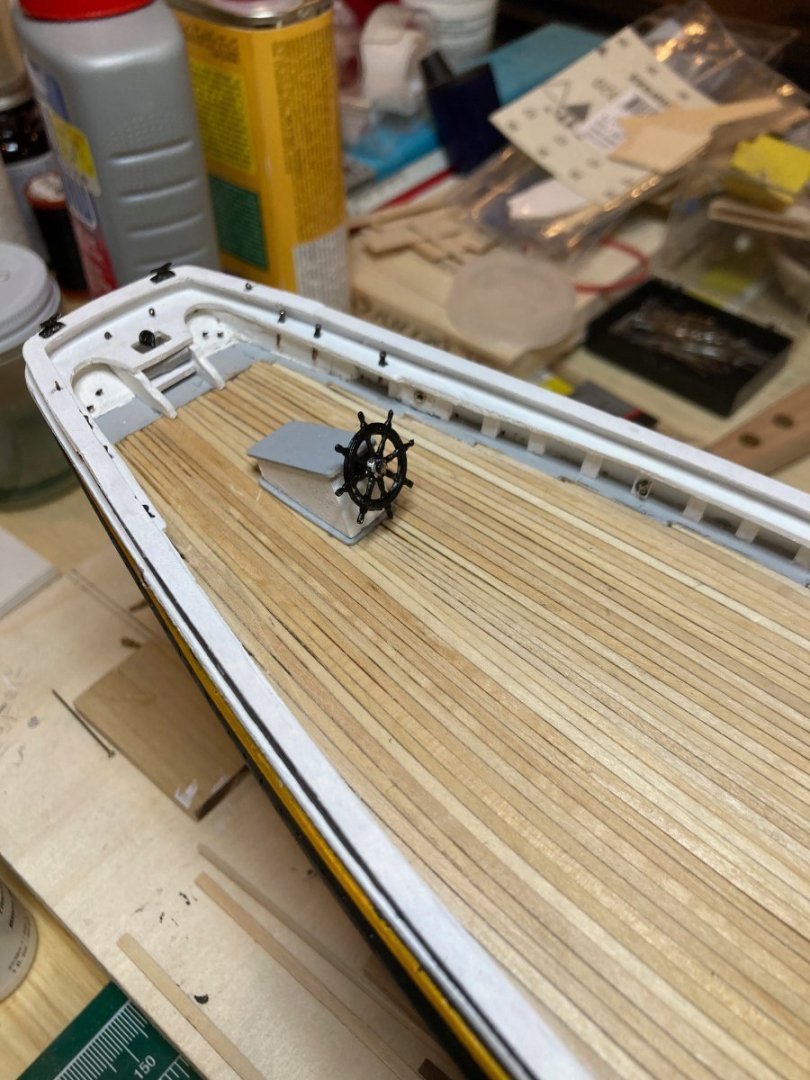
So I've finally more or less finished the detailing of the inboard bulwarks, rails and outboard hull. I realised that when I made the main rails, I forgot to account for an inboard extension through which the catheads run - I'll have to add this at some point soon. The chainplates & deadeyes need to be added for the fore and main shrouds, and I need to add the bobstay chainplates, decorative star, scrollwork around the hawse pipes and the name plates at the bow and on the transom - and of course the rudder! And the mounting! I guess I have quite a bit of work to do still.... In any case today I installed a series of ringbolts along the inboard bulwards as well as outboard on the splash rail and then some eyes for the bowsprit footropes. Nothing too exciting. But once this was done, I decided to work on the wheelhouse. I started by making the wheelhouse roof and coaming from a 1/32" basswood sheet and finishing both grey. For the wheelhouse itself, I took some 1/8" x 1/2" basswood stripping and cutting out 4 pieces to the fore-aft dimensions of the wheelhouse. When I sandwiched these together they were slightly wider athwartships then the wheelhouse, so I substituted one of the 1/8" thick pieces for a 1/16" piece and this ended up being perfect. I glued these pieces up and squared the rough edges using the disc sander. The main part of the wheel house was finished white and the roof and coaming glued on - again very straightforward work. I am leaving out some of the details featured on the plans as, on the one hand, I don't feel that I have the skills to work at such a small scale on such fine details (mouldings around the wheelhouse roof, chamfers along the corners) and on the other hand, I was worried that attempting to add them would just make it look clunky.... The ship's wheel was "borrowed" from another kit, in which a generous manufacturer had packaged 1 too many - the wheel was almost to scale, but is a tiny fraction larger than the wheel depicted on the plans - I don't think it looks too absurdly large. I inserted a toothpick into it for purposes of painting, but then figured I would just use the toothpick as the wheel shaft - painted black with the wheel, There is a little pad, cut from 3/32" x 1/32" basswood, that I drill a hole in with a needle file and then widened gently using the toothpick - I then cut a short section out of this strip and finished it black for the pad. Though you all probably know this, I feel obliged to say that by design the wheelhouse is shifted approximately 1/8" to port and the ship's wheel lies slightly to port of the wheelhouse centreline, which explains why in the photos it appears off centre on the quarterdeck. Here are some photos of the process and the completed wheelhouse. Enjoy and bye for now hamilton


-
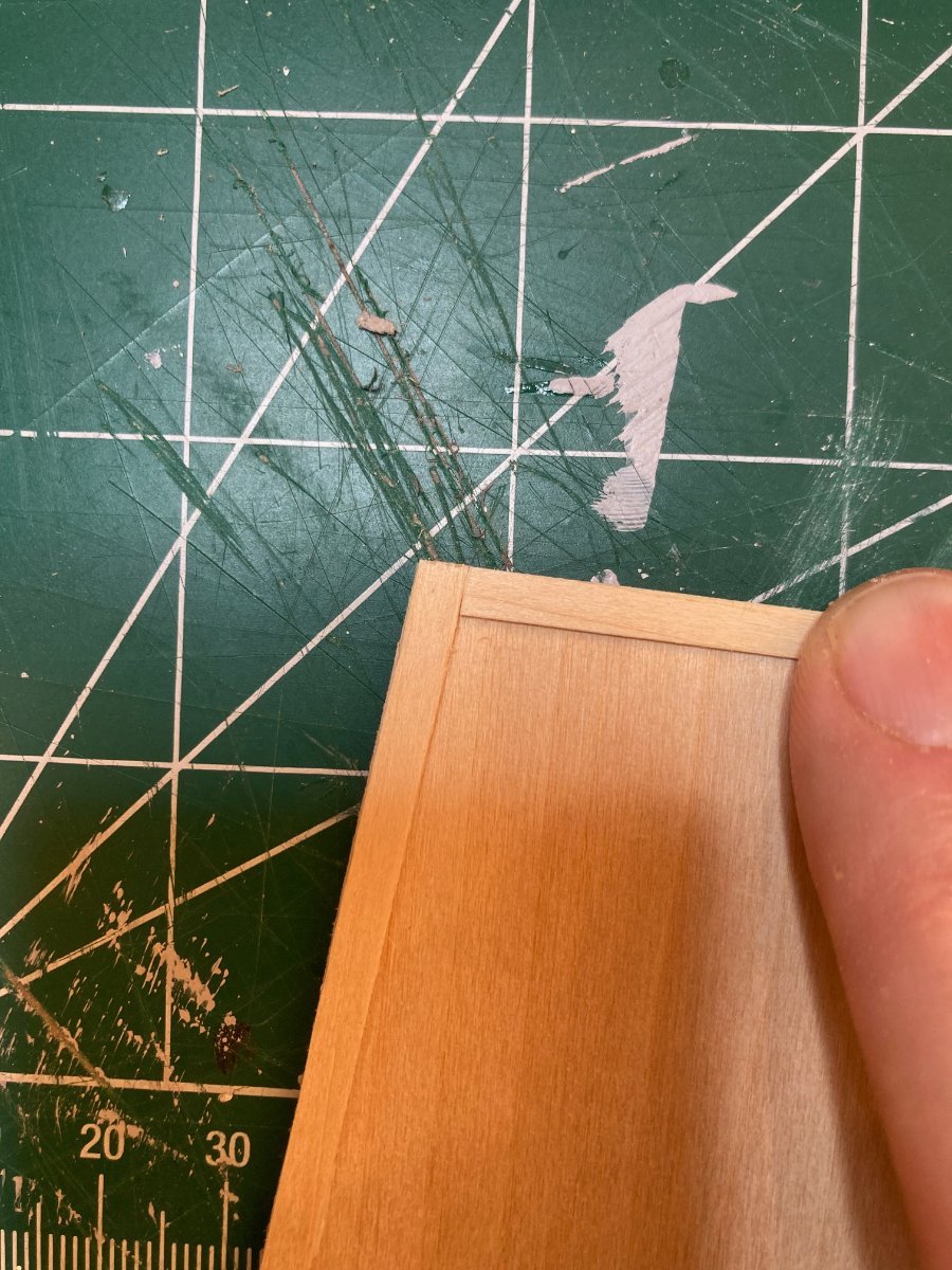
Hello all I've now completed the rail detailing and installed the monkey rails - have still some ringbolts to add to the inboard bulwarks and the fore and main chainplates, which I'm a little intimidated by to be honest. The monkey rail cap was pretty straightforward. I took a tracing of the curve of the monkey rail bulwark onto a 3/64" basswood sheet, trimmed the sheet along the tracing and marked out the width with a compass. I cut the part overlong because I wanted to use a trimming at the end for the part of the cap that runs down the curve at the front of the monkey rail (there must be a term for this that I don't know!). You can see this little off-cut in a photo below. This part was installed first and lightly sanded down so that the upper part of the rail ran over it. After installing the main cap, I then spent some time with sanding block and files refining the transition. The rest is just eye bolts and belaying pins - I can still not get blackening of brass done in the seemingly neat and tidy way I see in other builds. It always comes out somewhat fuzzy and flakey - I've read through as many of the blackening tutorials I can find and the results seem the same regardless of how I follow the tutorials....using acetone to clean the parts, diluting the blackening agent, etc....it always ends up looking pretty bad - what's your secret anyone who can produce cleaner results? In any case, enjoy the photos and happy modelling hamilton


-
Thanks Steve: Yes I do have a thought to mounting. I have cut out sections of the keel for mounting nuts and have already constructed a stand and some mounting posts. I have to replace one of the mounting nuts, but will do this once I reach a stage where I don't have to handle the hull too much and when it can be moved to a more permanent housing. All holes that need drilling have been drilled! One of the lessons I learned early on! Thanks again for coming bye - I like your Mayflower! hamilton