shipmodel
-
Posts
941 -
Joined
-
Last visited
Content Type
Profiles
Forums
Gallery
Events
Everything posted by shipmodel
-
 Beautiful woodworking JD, and what a sweet little plane. I'm a bit jealous of both. Dan
 -
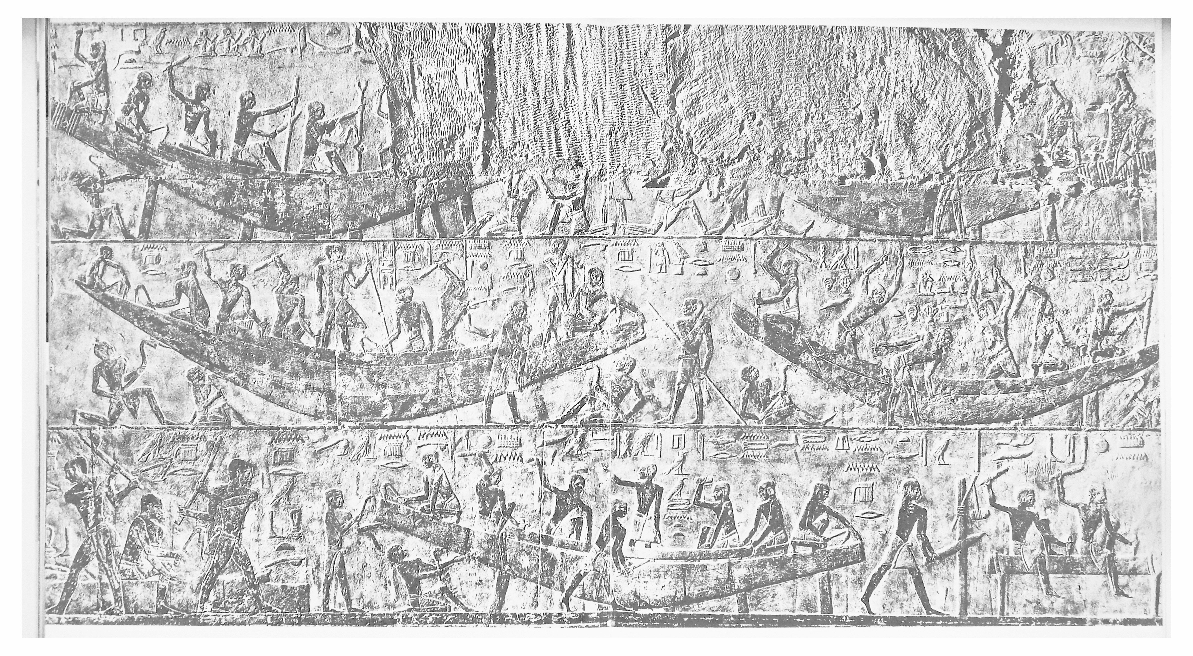
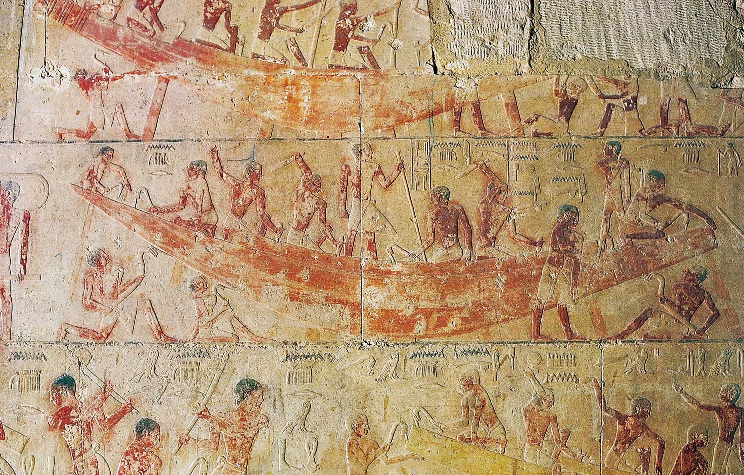
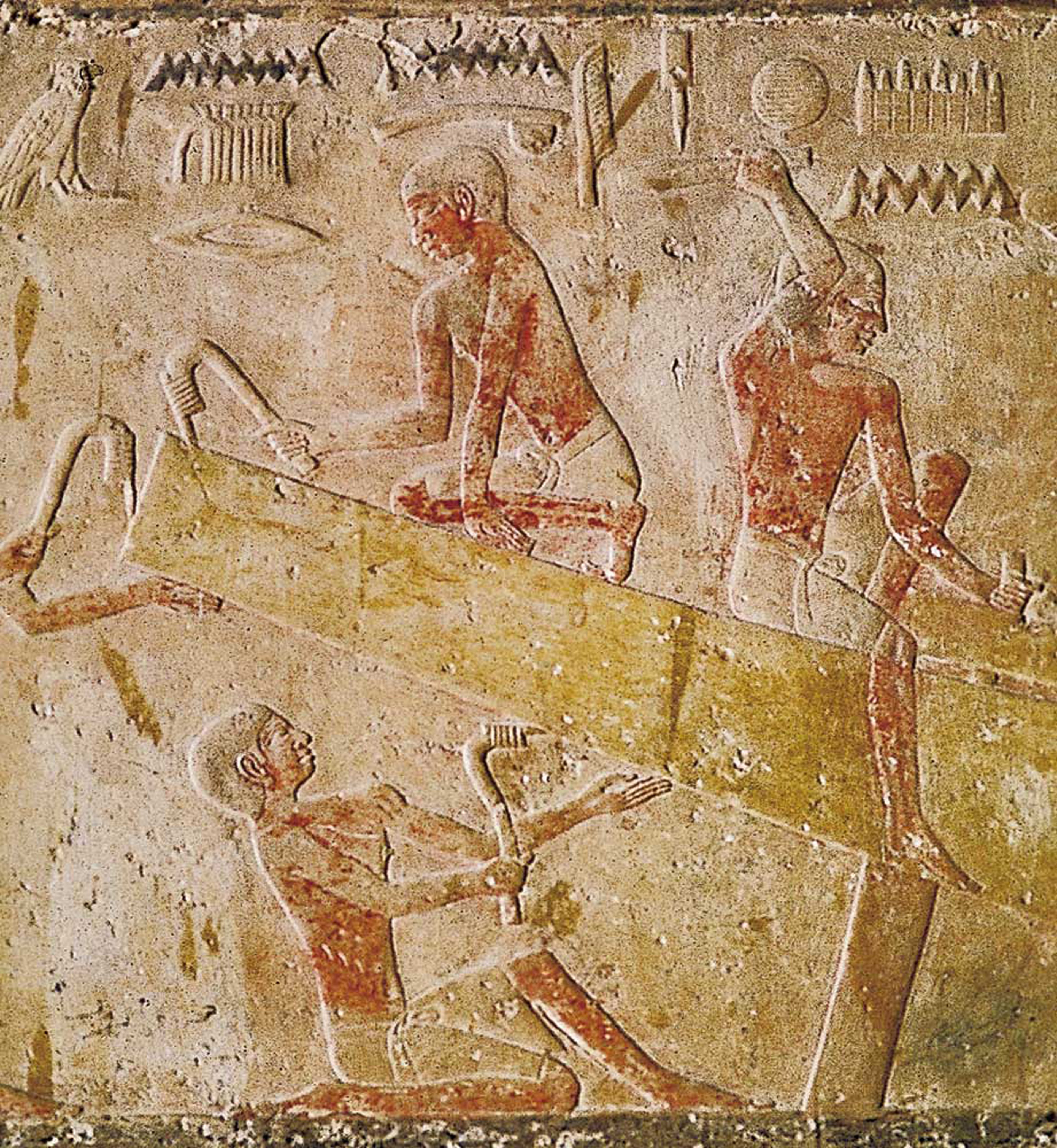
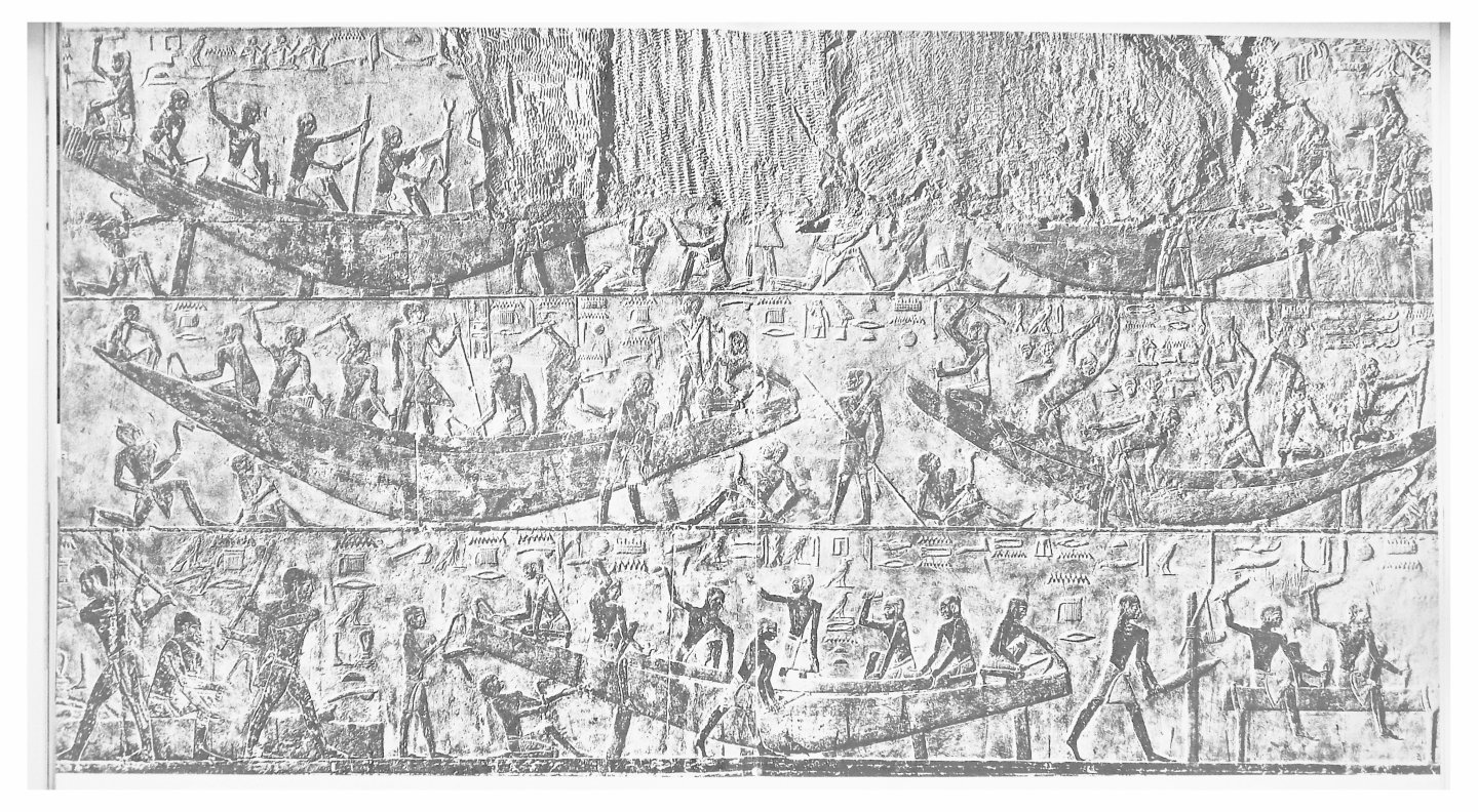
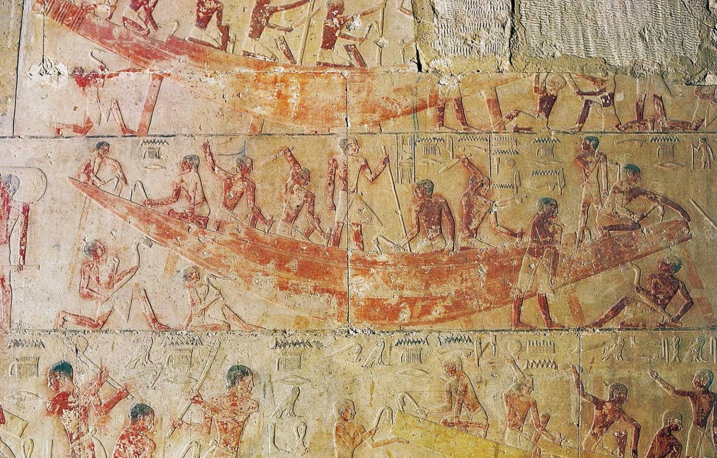
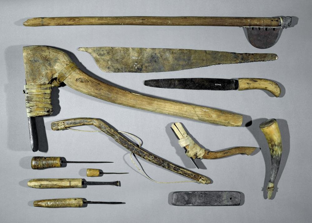
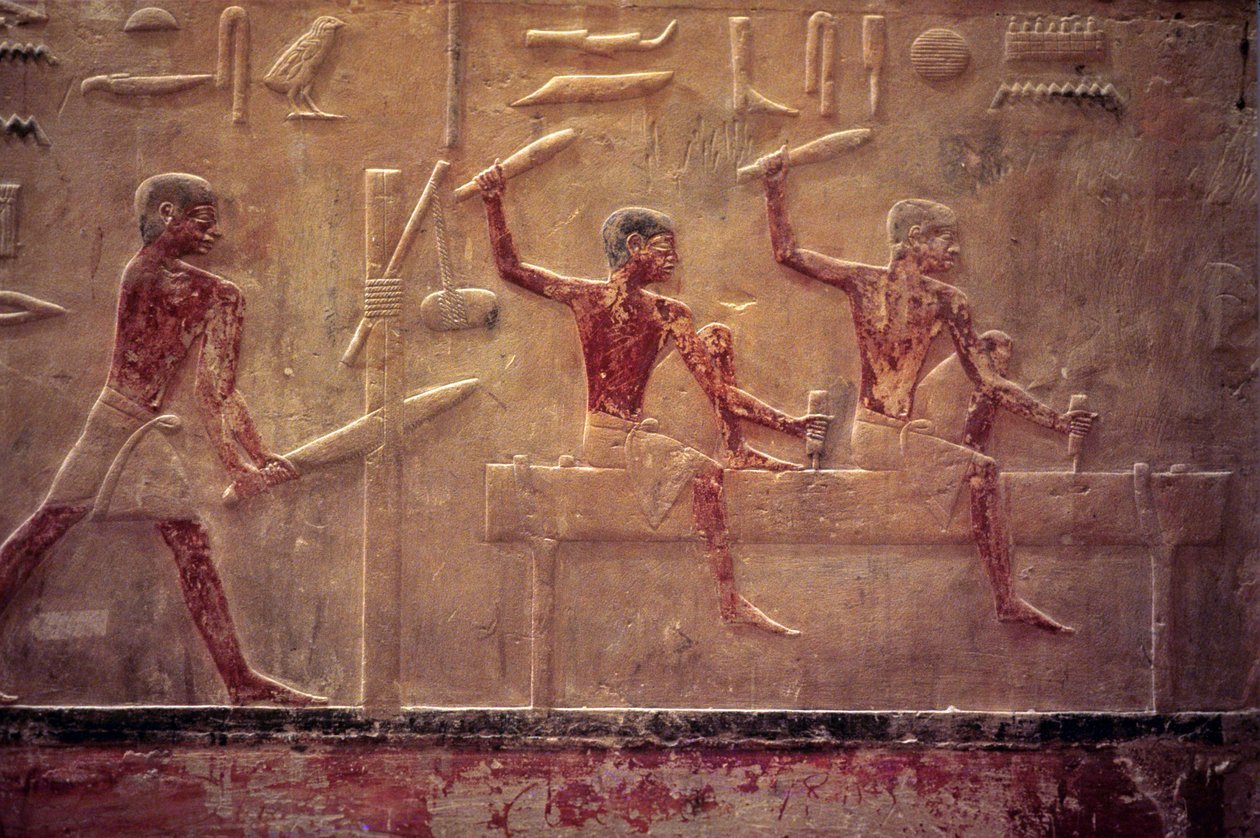
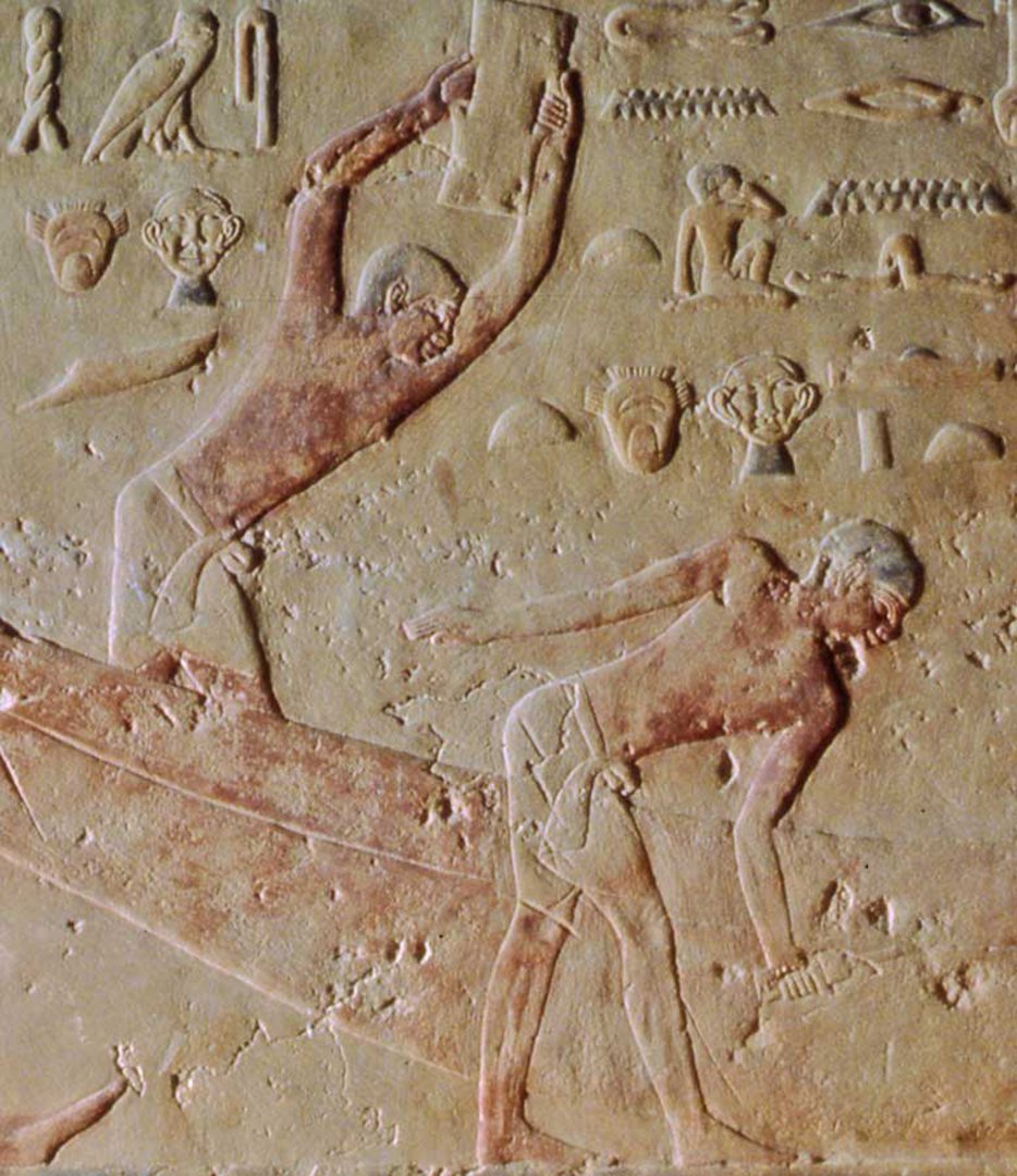
Hi again to all - Thanks for the likes and interest. My next segment was going to be the development of my scaled and measured working drawings. For the illustrations I need to include the copyright materials, for which I have only partial permissions. So instead, this will be part 3, a discussion of Egyptian construction methods, moved up to part 2. The sequence numbers for the images are therefore out of order, but they are all from open source websites. Before cutting wood, I wanted to look into historic Egyptian shipbuilding. I made a commitment on this model to build it by relying on the original Egyptian techniques, at least as closely as possible for only one workman building a miniature. So here is a quick dip into the original techniques might have been in use at the time that the Khufu ship was built. I was fortunate in this regard with information from a remarkably preserved tomb which has a series of wall carvings that show boats under construction. In the cemetery at Saqqara is the tomb, or mastaba, of Ti (or Ty). He was a long serving senior official and royal architect during the Fifth Dynasty, only 100 years or so after the Fourth Dynasty, the time of Pharaoh Khufu. The tomb was discovered in the late 1800s by French archaeologist August Mariette and has some of the best bas-relief carvings of daily life from Egypt’s Old Kingdom. In one of the outer chambers is a unique carved wall showing five boats under construction and two side panels with men working on planks for the boats. (Figure 21). It is a shame that I could not find a color image of the wall, just some smaller sections, since the carvings and even the polychrome pigments have survived for all this time. (Figure 22 – ti wall detail). Ti is known to have been in charge of the decoration of the tombs of several Pharaohs, so he must have had a long career where he was perfectly placed to assign the best craftsmen to work on his own tomb. In this close-up you can see that even individual fingers were delicately carved. You can certainly see what the workmen are doing and the strange tools that they are using. (Figure 23 – using adzes) Here are a selection of the actual tools. At the top is a large axe, with two different saws below it, while at the bottom left are several small awls and chisels. In the middle is a bent wood bow for a drill. The largest tool, the one the workmen are using, is an adze, like a plane blade mounted on a bent handle. (Figure 24 – tools). In Figure 23, above, three workmen are using adzes to trim wood and to smooth the outside planks of the hull, a technique called dubbing that is still used today. The quality of the carving is so high that you can see the subtle differences in the shapes of the adze handles to do the two different tasks. In the hieroglyphics there are representations of several tools. Above the upper worker is a short handled axe, a hatchet. To the right of the feather is an awl or chisel. Maybe the rest of the symbols are talking about that tool, but I have no idea. In the next scene a man is doing some sawing with a weighted stick and rope that is holding the kerf in the workpiece open (or closed, it is not clear). Two others are sitting on an upended plank and chiseling mortices into its edge. Above them seem to be carved images of the two types of saws and another chisel. (Figure 25). In the third detail image the first man is, I believe, using a two-handed sledgehammer. A similar type of hammer is still used to drive in fence posts. The second man, who seems to be left-handed, is holding an awl or a marking tool, it is impossible to tell. In the carvings the only thing that might be a tool is the twisted rope at the top left. But what the paired faces of the monkey and Alfred E. Newman are supposed to be saying, I truly have no idea. (Figure 26). What does all this mean for my project? That the ancient Egyptians built their boats with the same techniques that we would use if all the electricity were turned off. They were not stupid or unsophisticated, and didn’t need the help of aliens to build boats or pyramids. I feel confident that my use of similar techniques, but with a few power tools, will not compromise the historic accuracy that I am working to achieve. More soon when I can post drawings. Be well Dan

- 22 replies
-
- 10
-

-

-
Hi all - Glad to have you along for the journey. It will be a work in progress, both the writing and the building. I have just hit a snag, though. Not with the building, but with the writing. I have tried to use only open-source photos and drawings, but the technical drawings from Lipke and Mark are under copyright. I have contacted them and I expect permission soon, but I can't post my next segment until I do. Happy Thanksgiving to every one, American or not. Dan
-
Hi all - I have started another build log. This time I went back about as far as possible, to one of the earliest known wooden boats in the world. The funerary, or solar barge of Pharaoh Khufu is more than 4,500 years old, found in disassembled pieces in a limestone crypt next to his Great Pyramid in Giza, Egypt. I want to investigate its construction methods, so I am building a scale model of a cross-section of the boat. I will try to make it as accurate as possible to see what conclusions by earlier investigators can be confirmed and what new ones might be developed. The log can be reached by clicking on the image below, although I am trying to link it to my signature so it can be more easily accessed. See you there. Dan
-
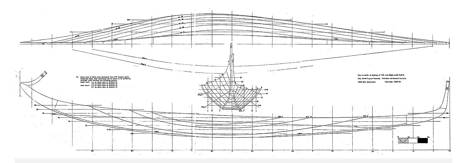
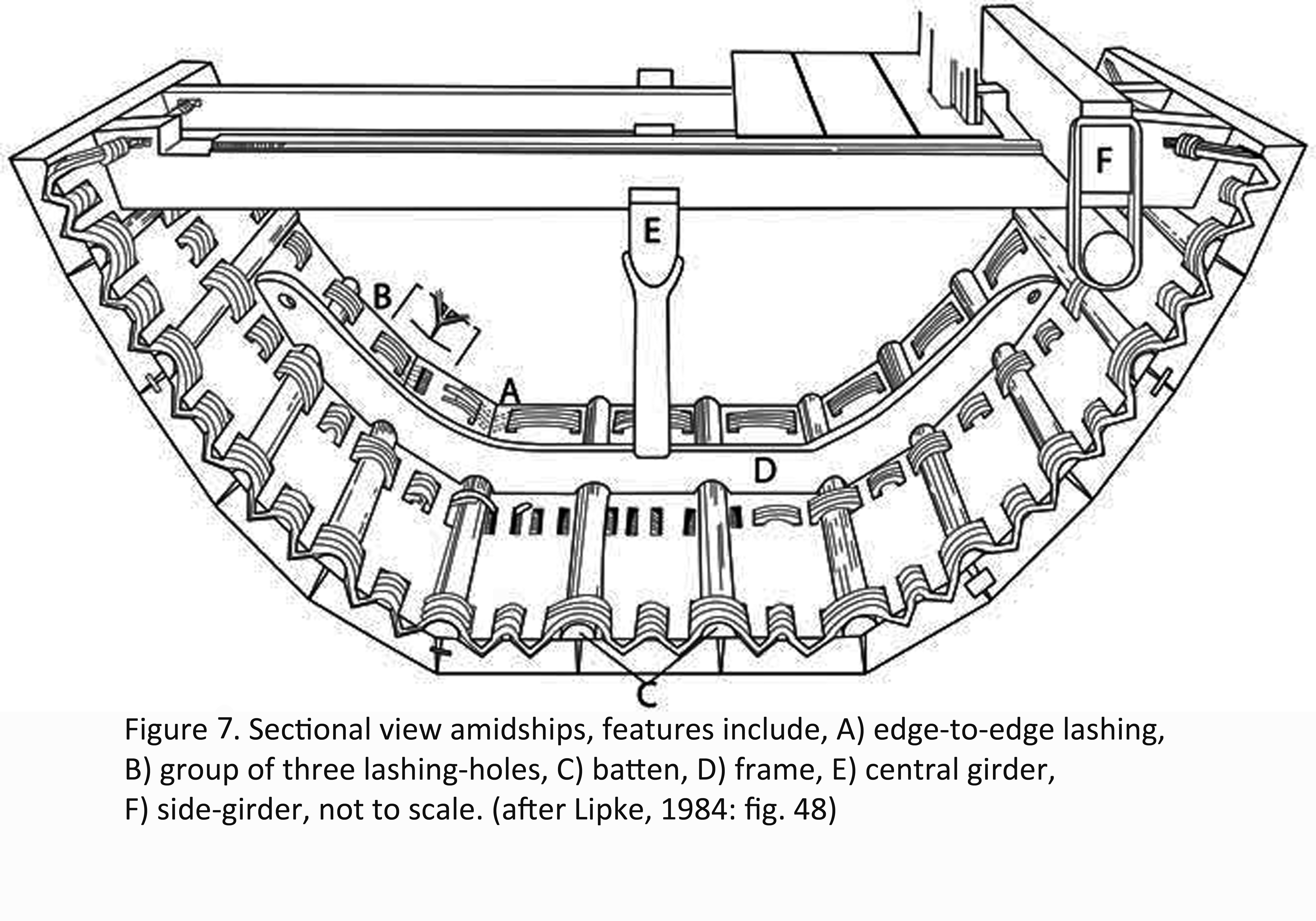
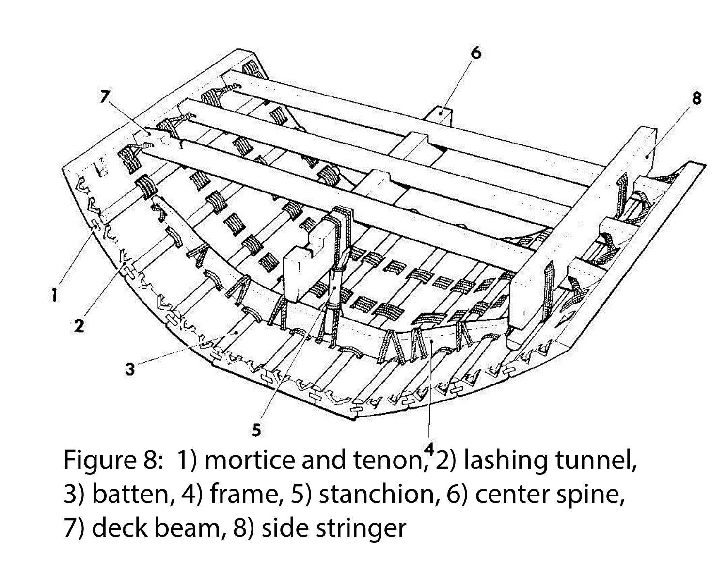
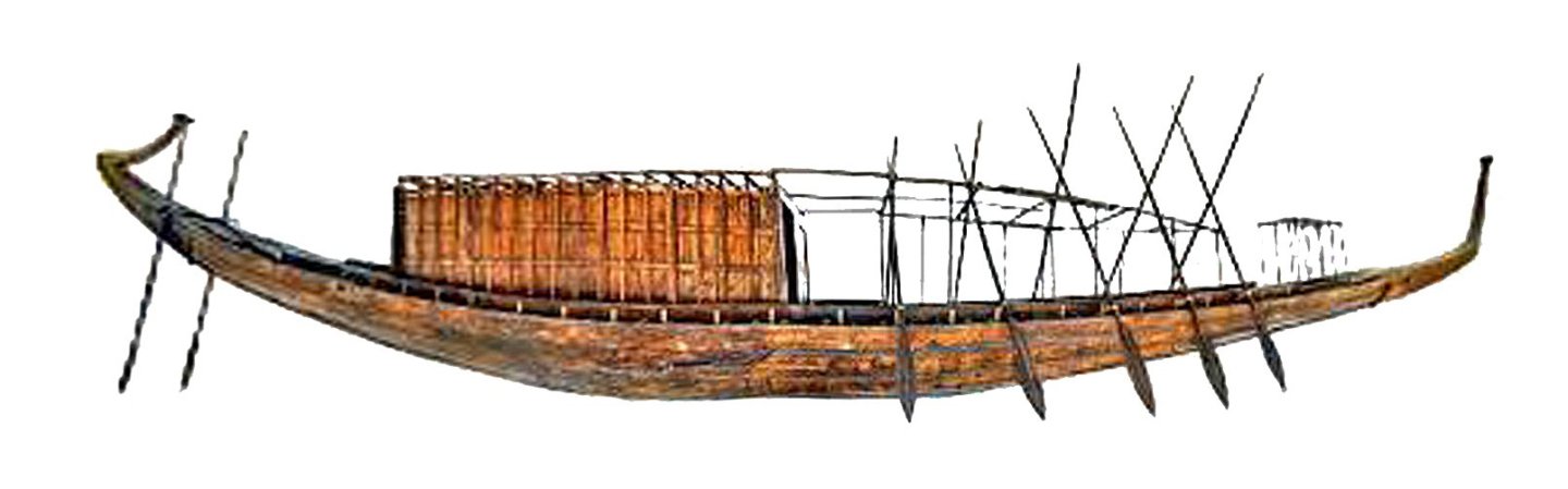
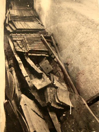
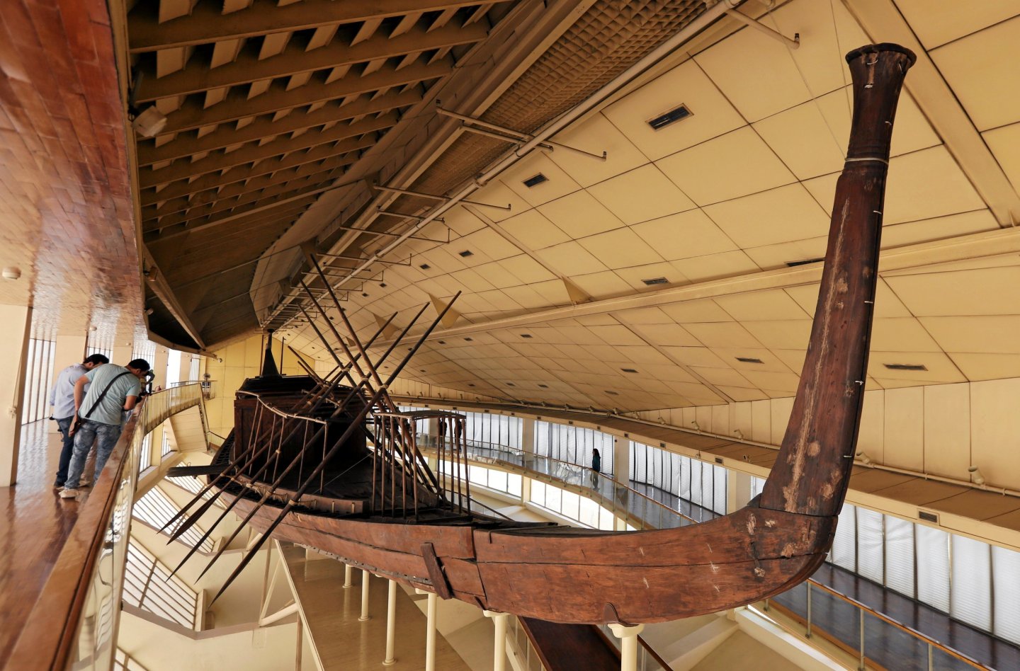
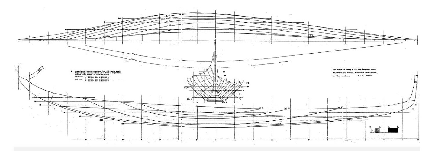
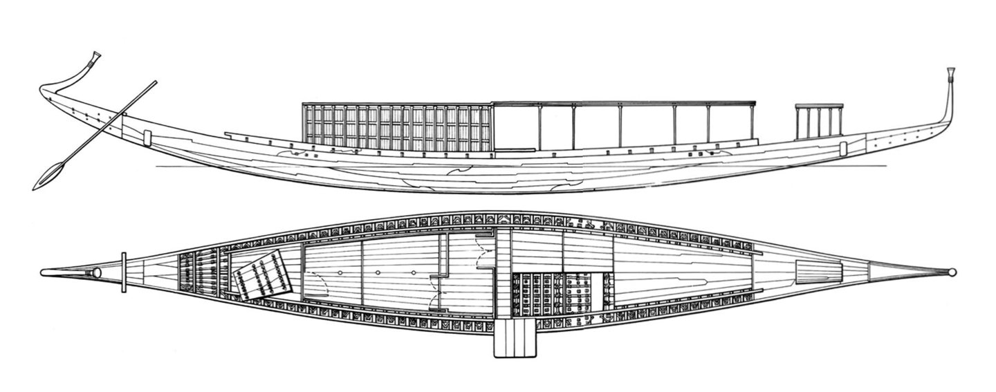
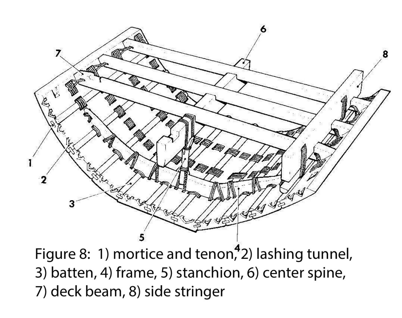
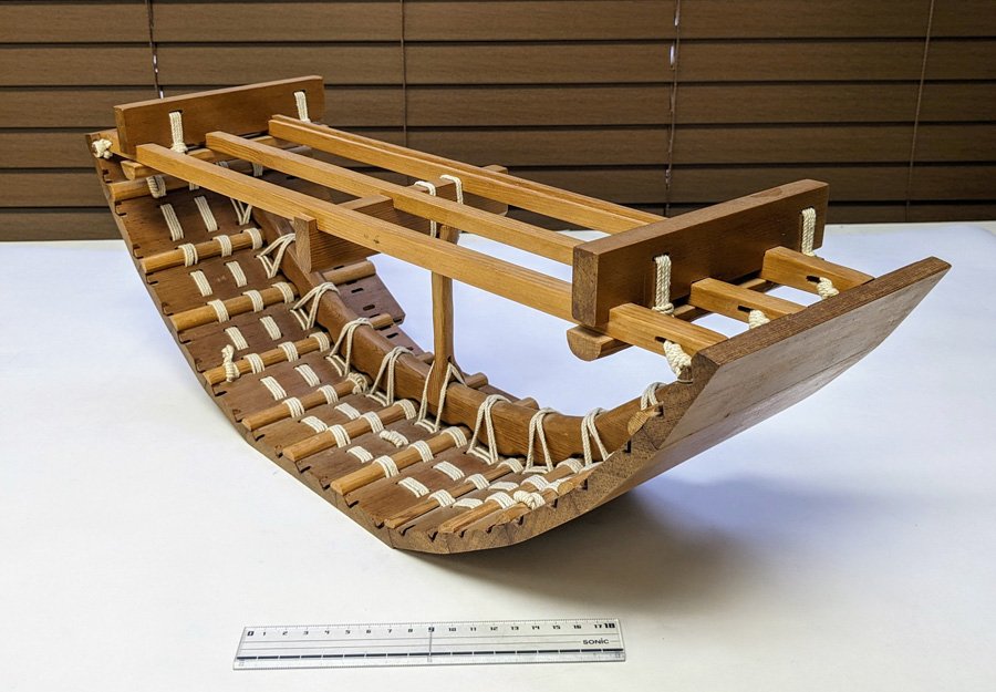
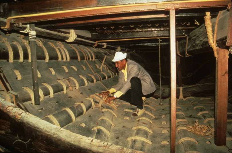
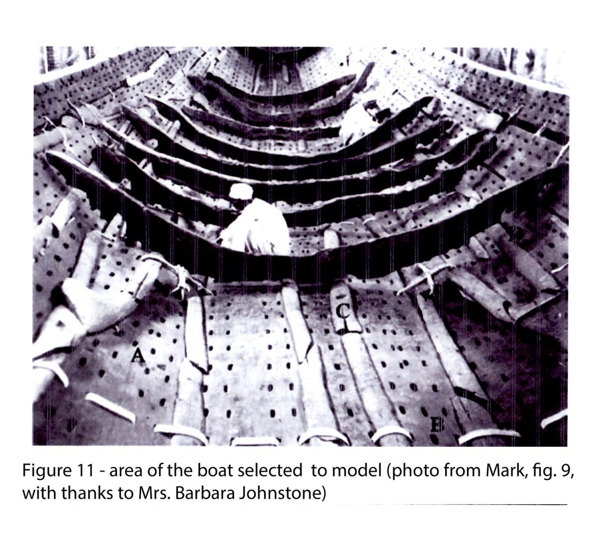
Some thoughts on the construction of the Khufu solar barge derived by building an accurate scale cross section model. By Dan Pariser First, thanks to all who have followed me from my prior build log of the SS Mayaguez. Thanks as well for all the likes and comments and suggestions that this community provided on that project. As will be seen, this project is based on information, plans and drawings which have much less precision and certainty than when I was building that modern steel-hulled ship. I invite and request that all of the readers of this log give me their comments and suggestions to improve the model and keep me from going too far astray. Part 1 - background and research Ancient civilizations have always fascinated me, especially Pharaonic Egypt, whose culture and religion were so focused on death and the afterlife. Other early peoples were certainly focused on death, mostly the death of their enemies in war, but this one was all about their own deaths. Strange. Somehow though, this philosophy led to some the greatest architectural, engineering and artistic works of the dawn of history. This was true in shipbuilding as well. Since the land is dominated by the long, straight river Nile, boats were incredibly important to move people and goods up and down its narrow fertile valley. Boats of all types are depicted on the walls of tombs and were taken into the afterlife as models which would magically become real for the use of the deceased when the right spells and chants were said. One of the oldest of these, and the best preserved, is the solar barge or funerary boat of the Pharaoh Khufu, also known as Cheops, the builder of the Great Pyramid at Giza. (Figure 1) He wanted to take it with him into the afterlife, not as a model, but the actual boat. To do this he had it fully built and then disassembled and buried in a sealed underground limestone crypt (Figure 2) next to his pyramid where it remained from about 2,560 BCE till being discovered in 1954, a span of over 4,500 years. Yet because the seals had not been broken the wood was still in remarkably good condition. (Figure 3). A team led by Egyptian archaeologist Dr. Hag Ahmed Youssef Moustafa spent 13 years putting back together its more than 2000 pieces. The fully assembled boat was displayed in its own modern purpose built museum next to the Great Pyramid (Figure 4). It has recently been moved to new quarters with better air conditioning in the Grand Egyptian Museum in Cairo. The saga of the discovery and reconstruction has been documented by American historic marine construction expert Paul Lipke (Lipke) based on over a hundred hours of translated interviews with Dr. Moustafa and hundreds of photographs and drawings of the boat and its parts made during the reconstruction. (The Royal Ship of Cheops, British Archaeological Reports, 1984). His fascinating and comprehensive report is mandatory reading for anyone interested in this iconic craft. He reproduces dozens of photographs of the reconstruction process and gives precise measurements for many of the boat’s details. He also drew preliminary scale plans of the boat. (Figure 5). Many additional photographs can be found in the book, “The Boat Beneath the Pyramid” by Nancy Jenkins, another must-read source, while other drawings and plans were developed by famed marine archeologist Bjorn Landstrom in “Ships of the Pharaohs”. The final source that was central to this article is “The Construction of the Khufu I Vessel (c.2566 BC): a Re-Evaluation” by Samuel Mark (Mark) of Texas A&M University, published in the International Journal of Nautical Archaeology (2009). From Lipke’s initial plans and measurements various drawings have been created of the boat which give a better idea of its particulars. (Figure 6). As you can see, the boat itself has a striking shape. It is quite long at 43.6m (142 feet), but with a breadth of only 5.9m (19 feet) at its widest point. Its shallow draft is only 1.78m (6 feet) from keel to sheer, with a freeboard from waterline to sheer of less than a meter. The boat tapers symmetrically to points at both ends which curve up high above the waterline with carved ends that reflect the shape of papyrus reed boats from the dawn of Egyptian history. On deck is a lightly built deckhouse which may have housed the Pharaoh’s coffin and a small open altar near the bow. Its construction is unusual to us as well. Hull planks, 12cm (5 inch) thick, are fitted to their neighbors with mortice and tenon joints. The planks are then laced to each other with ropes that snake through “V” shaped tunnels chiseled into the interior faces of the planks. Rounded battens cover the plank seams and are held in place with the same lashings. (Figure 7). Multiple beams span the hull from sheer to sheer, locked in place and strengthened by two notched side stringers above the beams and a central spine below. The central spine is supported on short stanchions which rest on frames which spread the deck loads to the bottom planks. These too are held in place with rope lashings. (Figure 8). Taken together, the wooden pieces and lashings form a truss structure which would have been quite strong and rigid. However, these cross sectional and perspective drawings are somewhat simplified and stylized. There are also two cross section models that I know of, but they are also similarly simplified, although the one built for Texas A&M University is quite accurate in its general configuration. (Figure 9). This is perhaps because no one has been able to accurately measure and draw plans based on the actual ship. Even the plans drawn by Lipke were derived from a 1:20 scale model built by Dr. Moustafa to aid his reconstruction work. Compared to photographs of the boat’s interior, the profiles in the drawings and the model are too high and steep, the planks are too regular, the battens covering the plank seams are too narrow, rounded and straight, the lashings are too regular, and the tunnels that the lashings go through are not accurately represented. (Figure 10). Because of this, certain conclusions about construction methods and sequences have been made which are, in my opinion, somewhat inaccurate. I decided to attempt the construction of a precise scale cross section of a specific location in the boat to see if I could replicate a workable method and sequence for how it might have been built. I also resolved to build it as was done by the Egyptians, with mortice and tenon joints, rope lashings, and, most of all, no other fasteners or glue. To do this, instead of relying on the prior drawings I went back to the original boat. Although I have no access to the boat itself, there are photographs of the exterior planking and interior structures which are reproduced in the several sources mentioned before, as well as on the internet. I am also indebted to Mr. Lipke who kindly provided me with others from his personal collection. Then there are the drawings created by Dr. Moustafa from the boat pieces, as reproduced by Lipke and Mark. Though many are noted as not being to scale, they are the closest to accurate drawings as can be found. Wherever there was a conflict between the photos and the drawings, I went with the photos. Finally, there are drawings on contemporary tomb walls showing boats under construction, as well as academic studies of contemporary boats which also informed my investigation, and which will be referenced later. These were used a supplements to the first two. From these I selected one photograph which contained many of the construction details that I wanted to recreate. Here is that shot, an interior view of the hull taken during reconstruction. I call it my Primary Photograph. (Figure 11). Contrasted with the simplified drawings and models, it shows planks of various widths and shapes, lashing holes in irregular patterns, and flat battens which are pieced together from short sections with angled ends. Note the large triangular batten piece to the left which must cover seams between several planks. Based on the photo I decided to build out the model from the line of lacing in the foreground to just beyond the dark frame, which would then include the large square batten pieces tied with crossed ropes that are sitting just in front of the frame. This would give the model sufficient visual interest for the viewer yet still allow my close adherence to traditional building methods. Next time, the development of the working drawings. Be well Dan


- 22 replies
-
- 19
-
-

-
Hi Marc - Thanks for the compliments. It's always gratifying to pass along the tips and tricks that I have worked out over the last 35 years. I used to teach rigging seminars for the Guild, but they have been phased out. I keep thinking that I will write a book one day, but it has never really gotten off the ground. Happy to have helped. Dan
- 2,696 replies
-
- 3
-

-
-
- heller
- soleil royal
- (and 9 more)
-
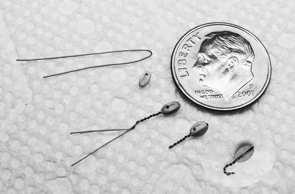
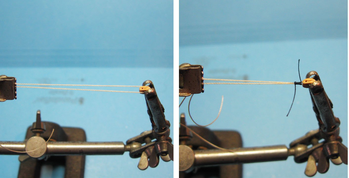
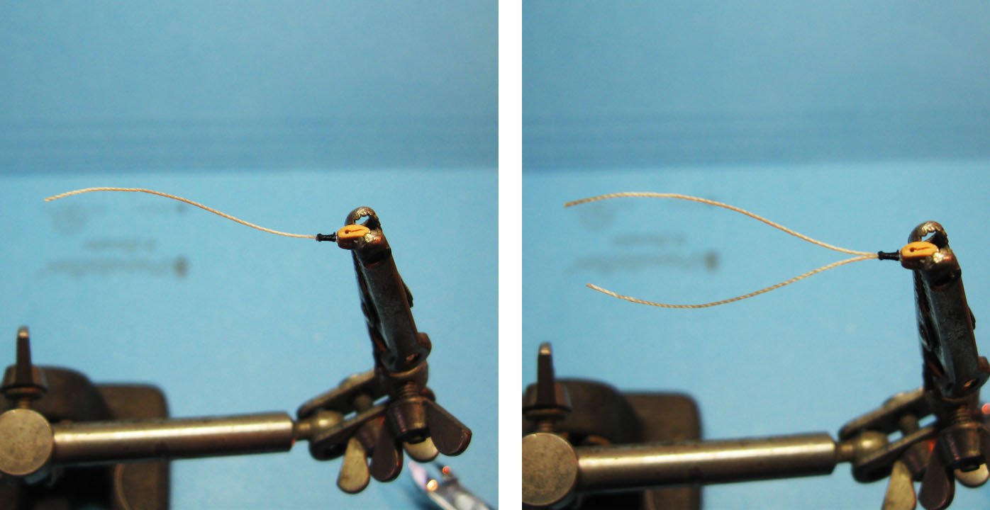
Hi Marc - The Helping Hands and the fly tying thread will make a significant improvement. Go with that if it works for you. Here is another solution that works in small scales like yours. It relies on stropping with wire and making the hook an integral part of the strop. The photo is pretty self-explanatory. The block is 2mm from Warner Woods West. You can add to the realism with a quick layer of paint on the hook to minimize the look of the twisted wire. A line can be tied to the other side of the block to start the lacing from block to block. Best of success Dan
- 2,696 replies
-
- 5
-
-
-
- heller
- soleil royal
- (and 9 more)
-
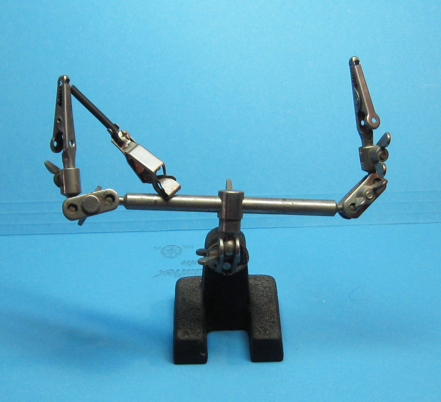
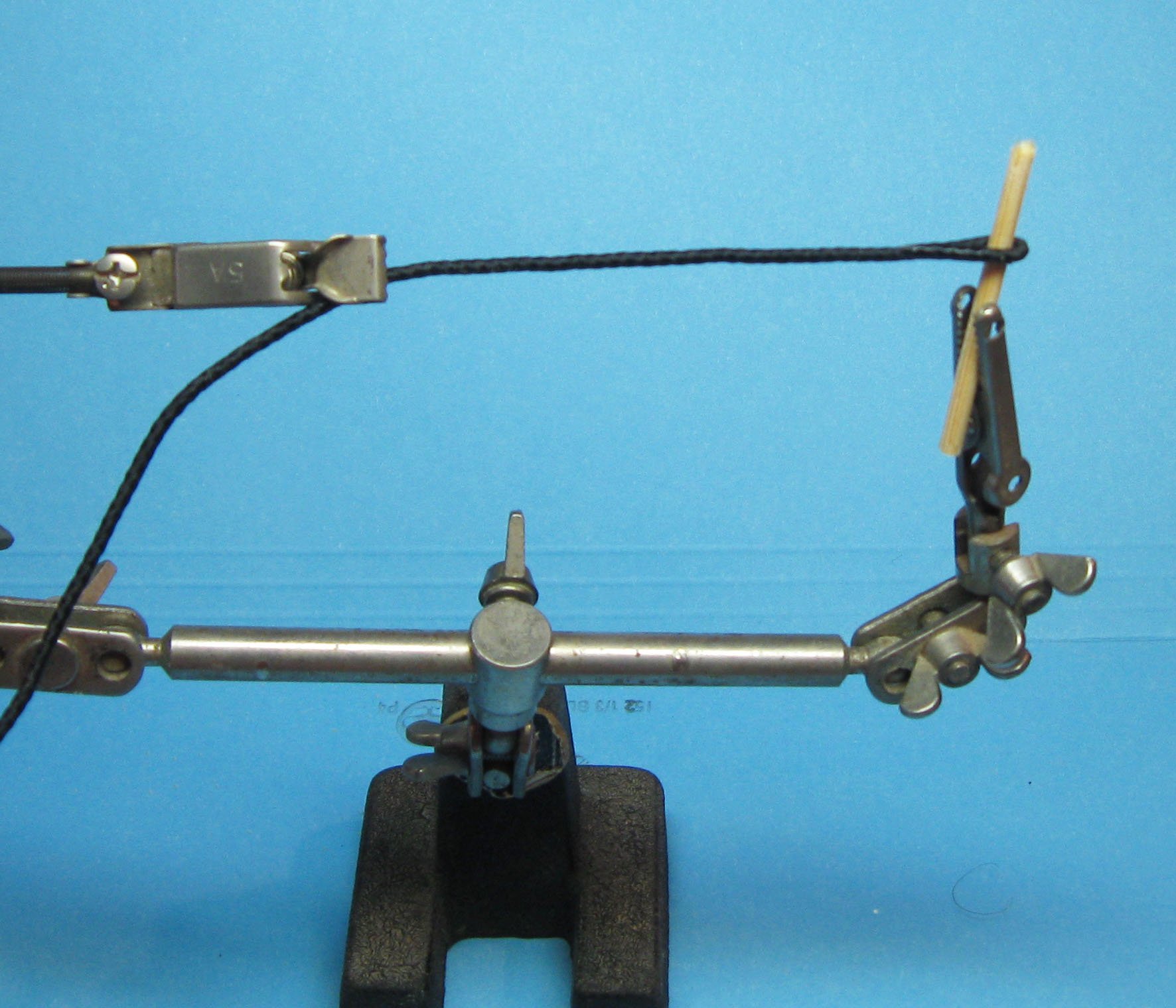
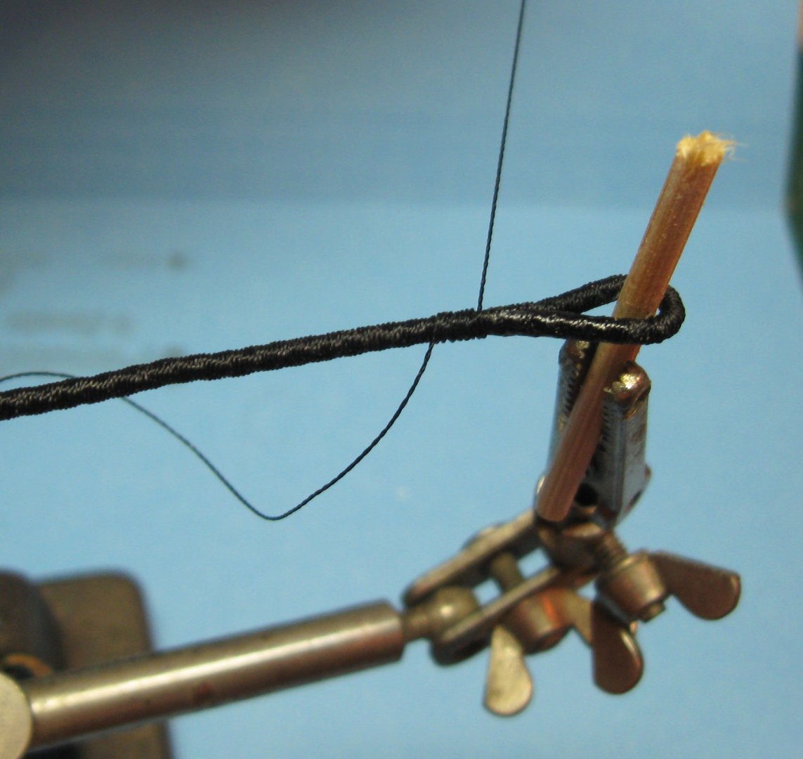
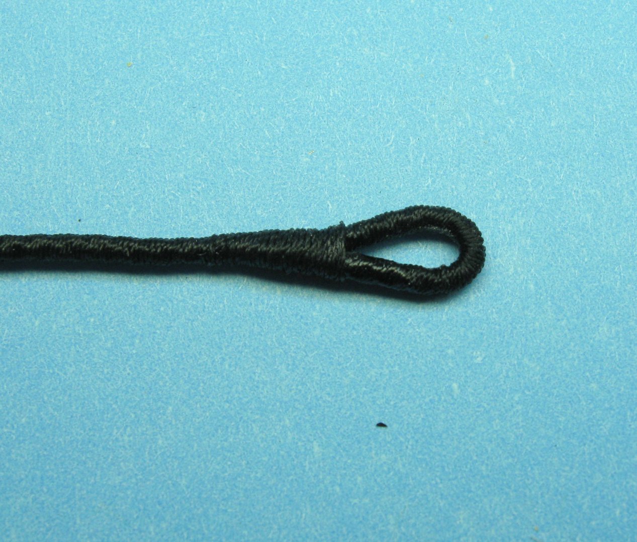
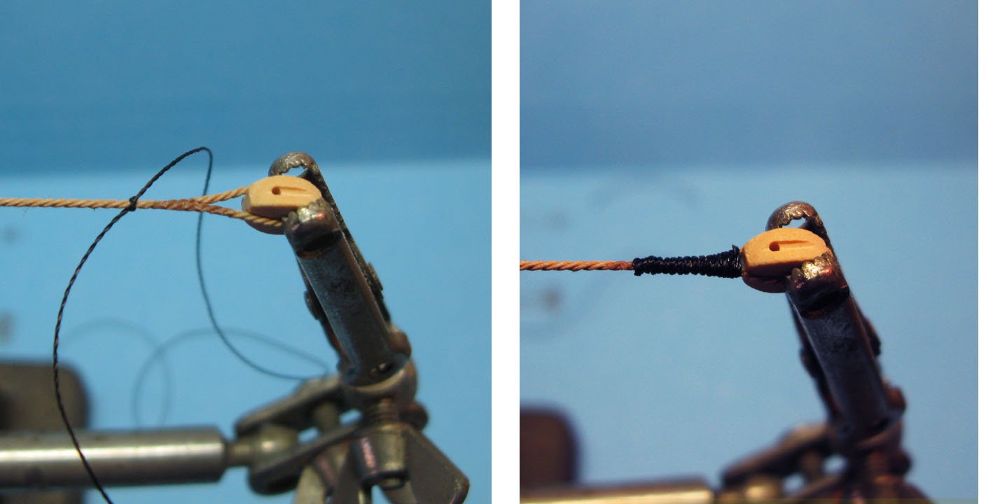
Hi Marc - Back in the city for a few days and had the time to catch up on your incredible build. All of the figures are so lifelike and posed so naturally. Your talents are so great, why aren't you making tons of money doing maritime paintings? No one ever got rich making ship models. LOL Sorry you had trouble rigging small blocks. If you intend to fully rig the ship you will be doing it again and again, and again, . . . and again . . . . . I have found that the Helping Hands type of tool is, in fact, quite a help. I add a light spring and a small alligator clamp to one side, which keeps the eye splice, block, stropping rope, and any hook or thimble together and under tension so they can be worked on. Here are some photos, which are really self explanatory - - - You can use the same setup for a wide range of sizes. The block in the last two photos is 2mm long. I hope it makes sense and helps. Dan


- 2,696 replies
-
- 6
-
-
-
- heller
- soleil royal
- (and 9 more)
-
Mark - I don't believe that I will ever build such a large, complicated ship in the years remaining to me. But your explanations have been fascinating and your drawings and illustrations have been brilliant. Thanks for a diverting, engaging, and educational build log. Dan
-
Hi Marc - Really nice looking work, and thanks for taking us on the journey, potholes and all. I had the same question as Kirill. How did you aim your deadeye/chainplate units at the future masthead location? Dan
- 2,696 replies
-
- 4
-
-
-
- heller
- soleil royal
- (and 9 more)
-
Hi Cisco - I really like the half-lapped miter joints. I have always used simpler lap joints, but yours are beautiful, justifying the extra work. If I have a suggestion, it is to make the gratings first, before the coamings. If a coaming is a little larger or smaller than the plans, no one can tell. If the grating does not fit the coaming, everyone notices. Looking forward to more. Be well. Dan
-
Hi Jesse - It was a pleasure to meet you earlier today and look at this little gem in person. I think you made an excellent go of the many issues and problems that you encountered in your first wooden ship model. Keep up the good work. You asked about some of my other works, and you can see some of the build logs in my profile, or in the Gallery. I'm always happy to answer any questions that may come to mind. Be well Dan
-
Hi Ron - Really good to meet you and to see Oneida. She is even better in person than on MSW. Great job. Dan
-
Hi Ron - Nice work on the steps. Building something as complex as a ship model always requires dozens and dozens of individual decisions. I like the ones you have made. I hope that I will get to see her in person in New London at the end of the month. Dan
-
Hi Ian - Really nice work on the ship. I am truly envious of your expertise with 3-D printing. It is a technology that I have not mastered and am reduced to buying pre-made parts from Shapeways and then modifying them as needed. Very well done, sir. As for painting, perhaps you could paint the fingers black first, then overpaint with silver, which you can access easily from both sides. You should be able to get clean separation lines either freehand or with some fairly simple masks. Dan
- 536 replies
-
- 4
-
-
-
- Quadrireme
- radio
- (and 1 more)
-
Keith - Look for figures in the model railroad TT scale which is 1:120. I took a quick look and Preiser has a set of about 50 unpainted railroad personnel for $18. You will have to select and adapt them, but it is a good place to start. Eberhard - Really excellent work. Your deck fittings and fixtures at your scale are wonderful. You might look into making your guy wires and other lines out of polyester fly tying threads that go down to 0.003" diameter and can be tensioned after installation by heating with a just-extinguished match held under the line. As always, best of success to you. I will continue to watch with interest. Dan
-
Hi Mark - Happy that you are back and even happier that you are healthy. Excellent drawings. They really give a good idea of the interior structure of the ship. Dan
-
Hi Marc - I finally am getting your updates, and love what you are doing. The gun carriages look fine, and no one the wiser. As for making chain at 1:96, even the old "scratch built" rules allowed for purchased chain. (I have extra chain in really small sizes if you need some). If you are talking about deadeye chainplates, then you are on your own. You might be able to take larger size chain and squeeze the links into thinner, longer shapes. Best of success. Dan
- 2,696 replies
-
- 5
-
-
-
- heller
- soleil royal
- (and 9 more)
-
Hi Cisco - Nice work. Your skills and attention to details are well on their way up the learning curve. Looking forward to watching further progress. As for soldering, I have found that for the tiny parts that we work with a torch is just too powerful, as you found out. A mini soldering iron, like those for the electronics industry and hobby market, works well. I also like using a resistance soldering iron that has no flame or heat (it is sometimes marketed as Cold Heat). It is a bit trickier to use, but the lack of open heat more than makes up for it. Best wishes for continued success in your project. Dan
-
Nice repair. Your skills are improving steadily. Congratulations. Dan
-
Hi Cisco - Very nice planking. Excellent symmetry. Good choice on the cradle carvings too. Looking forward to seeing how they come out. Happy Holidays to you and yours as well. Dan
-
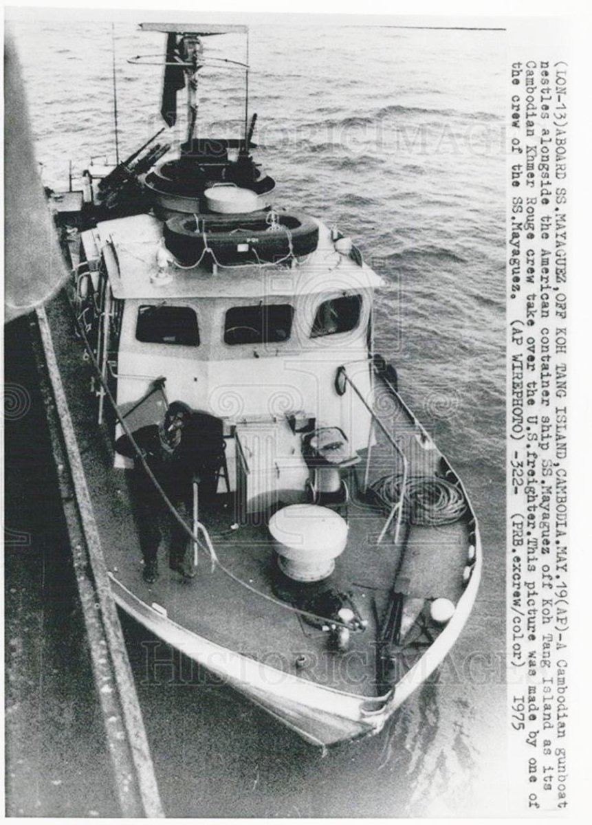
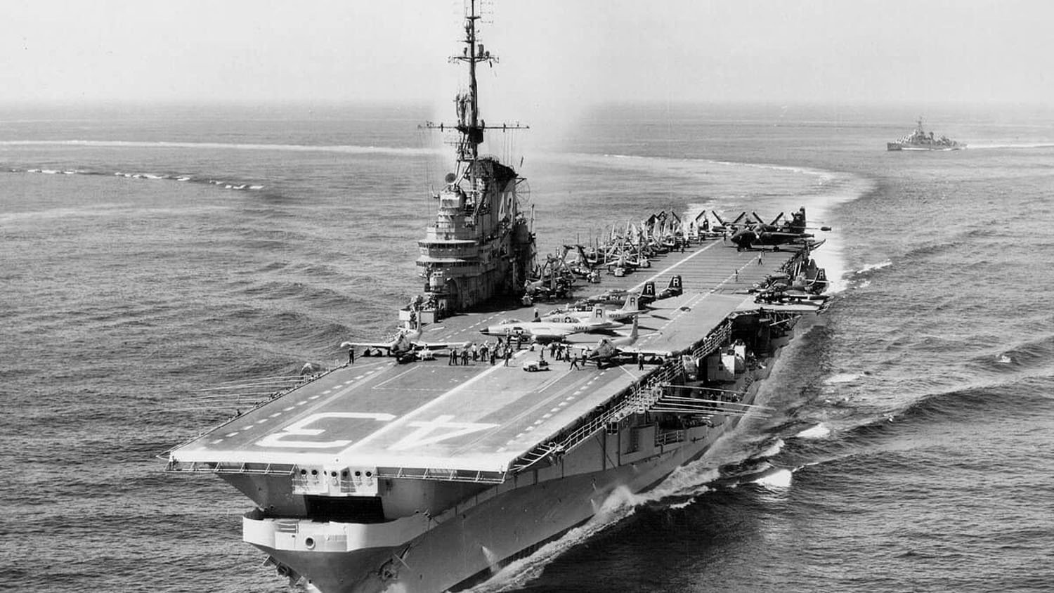
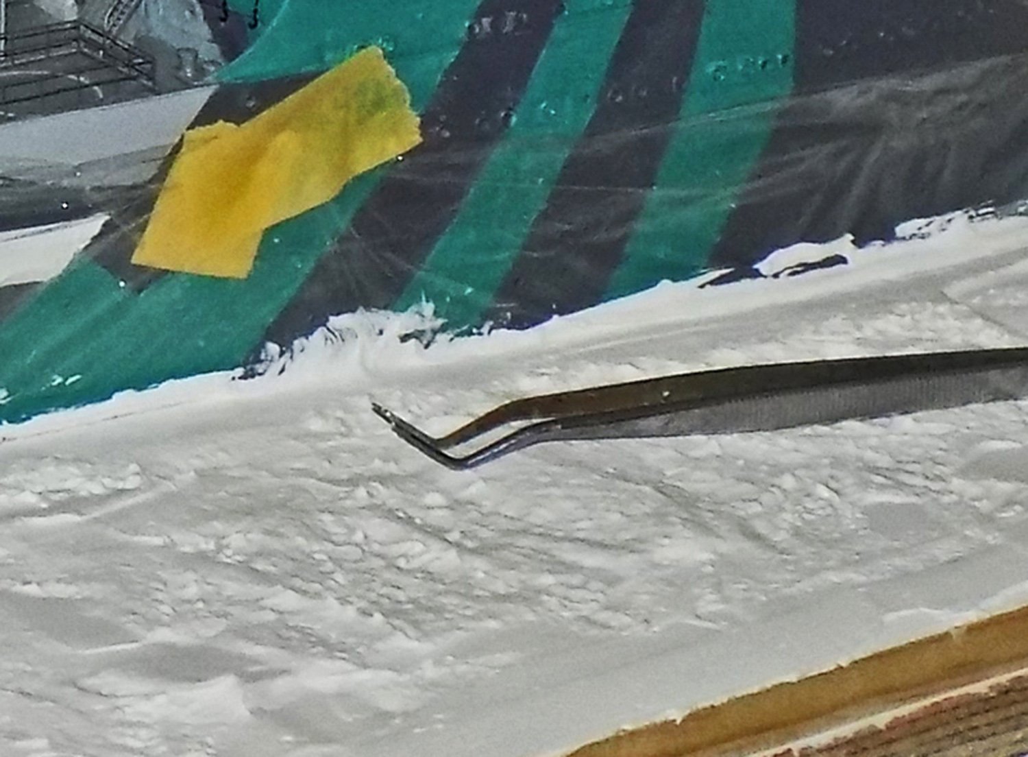
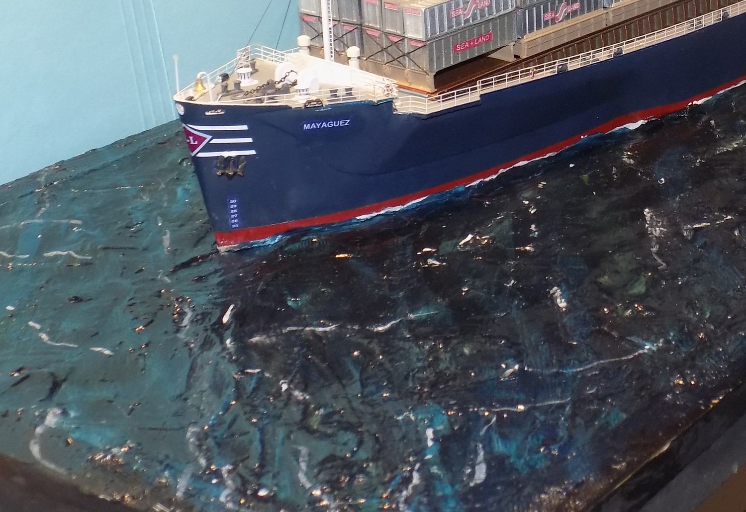
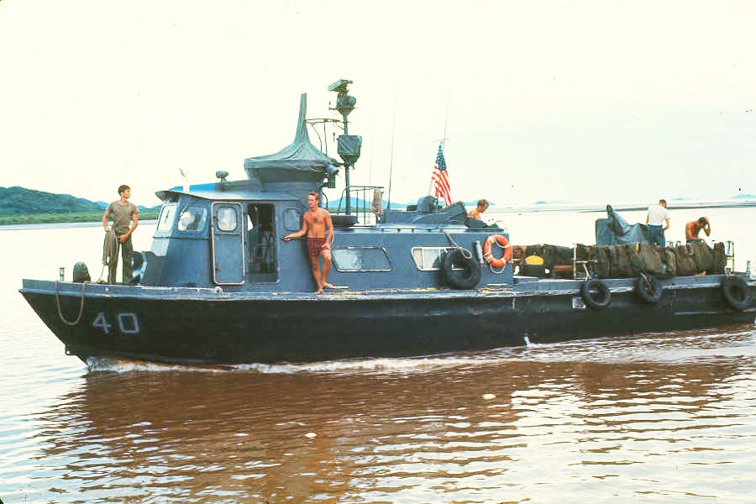
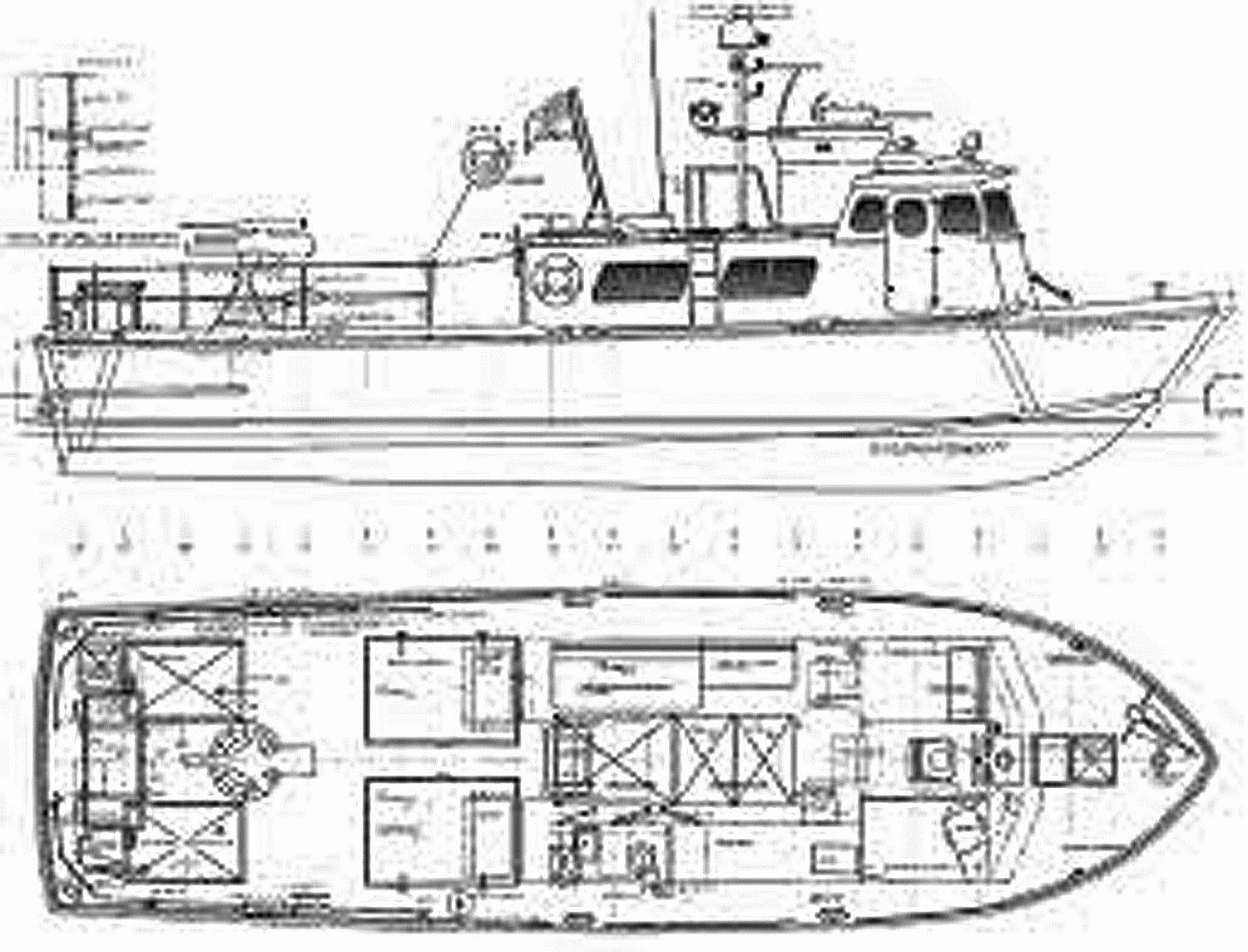
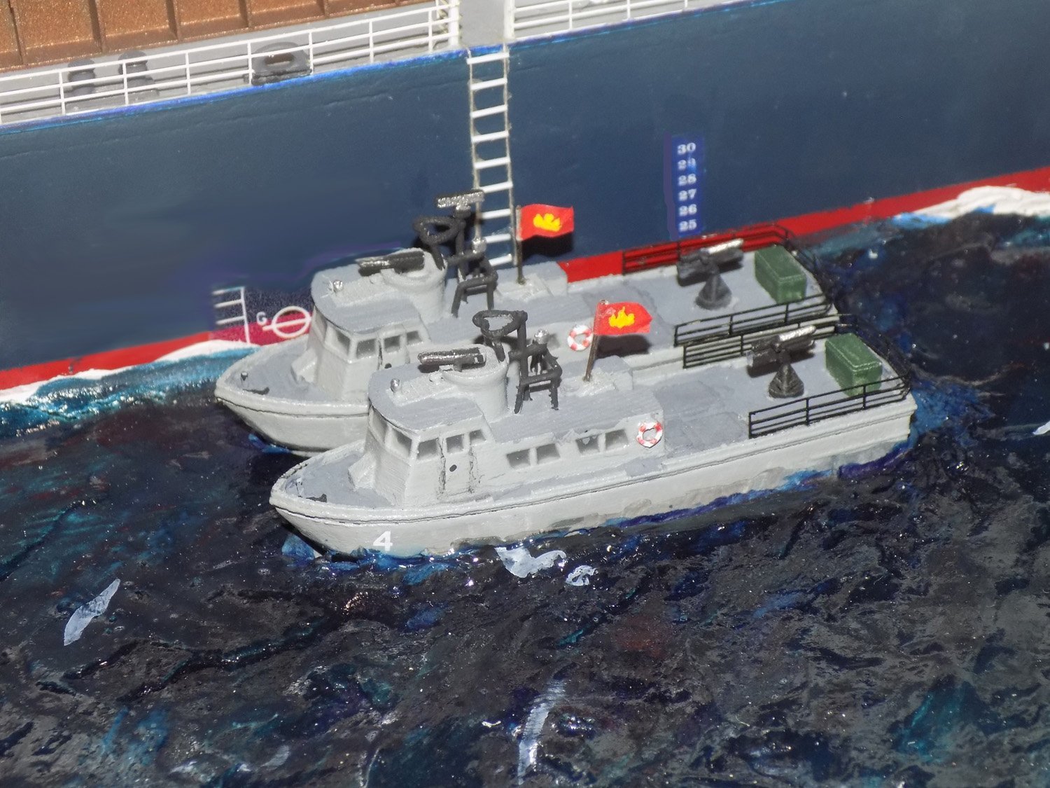
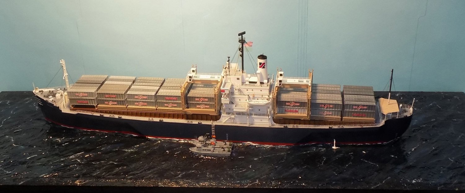
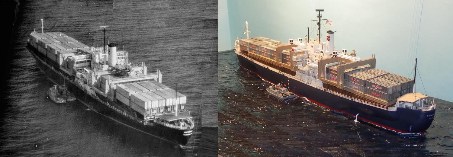
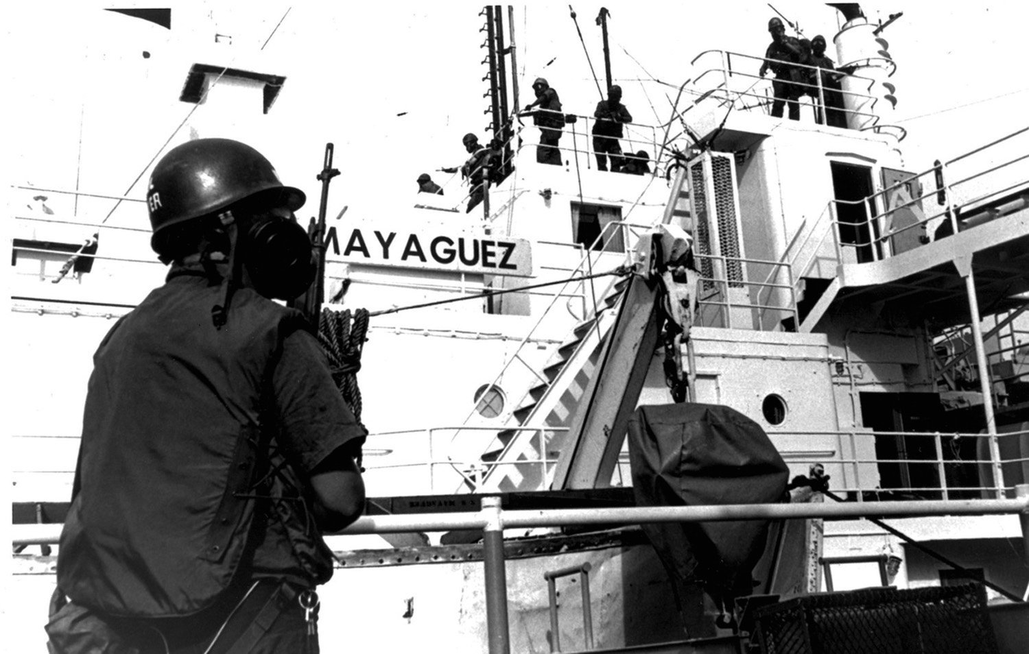
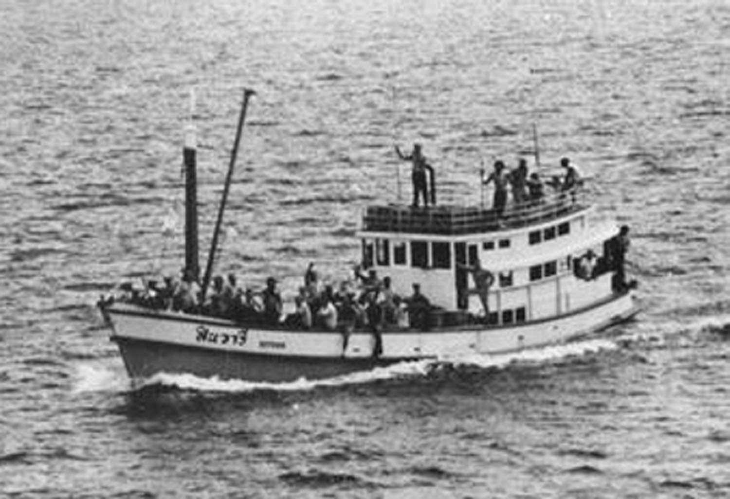
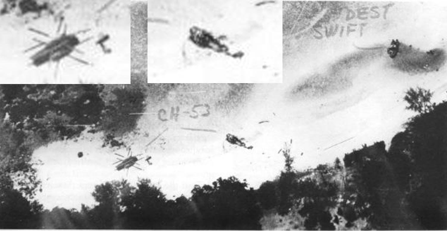
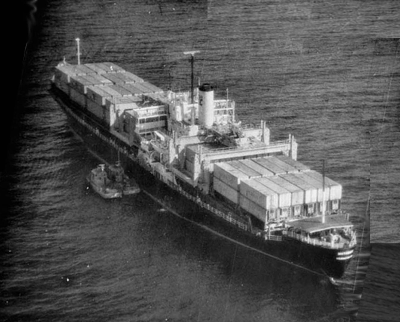
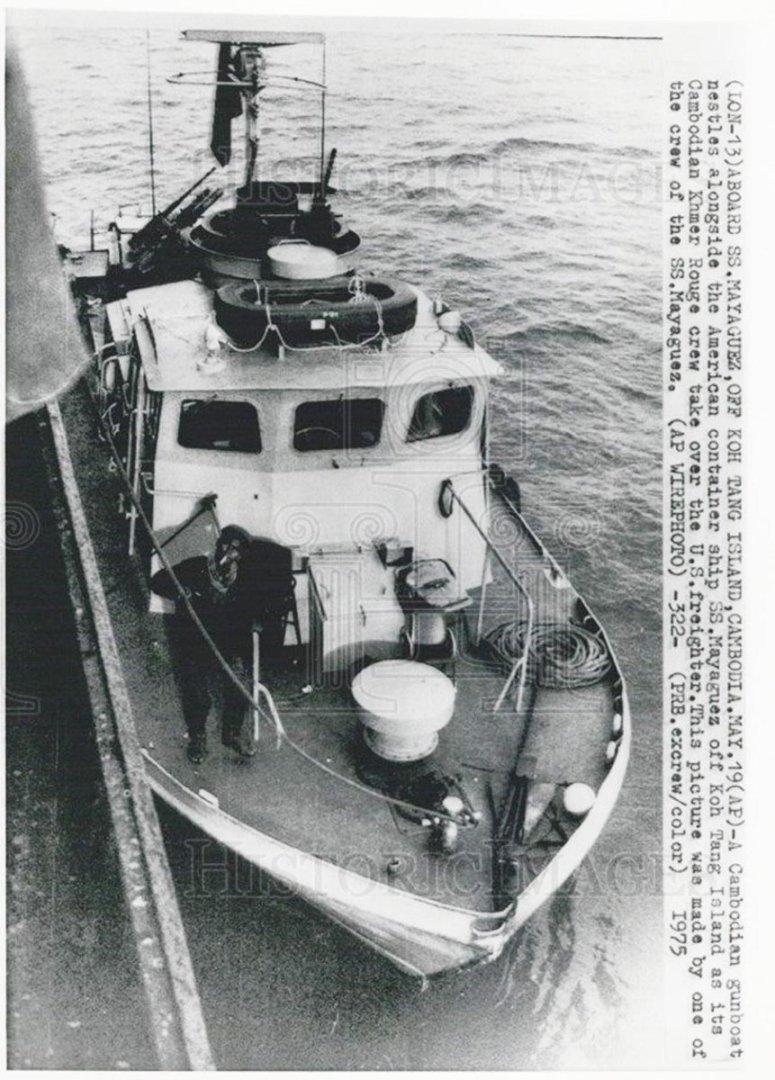
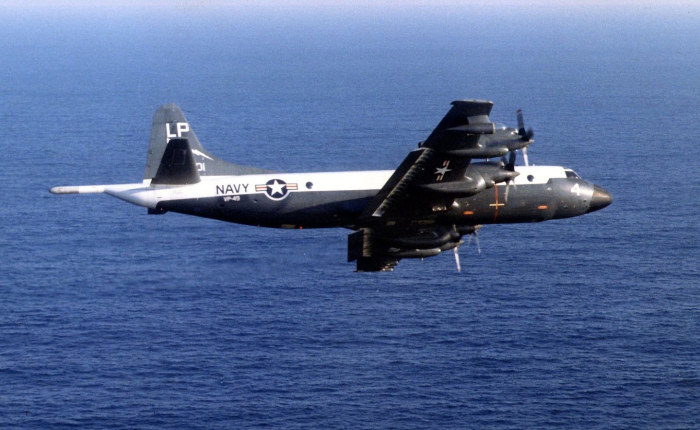
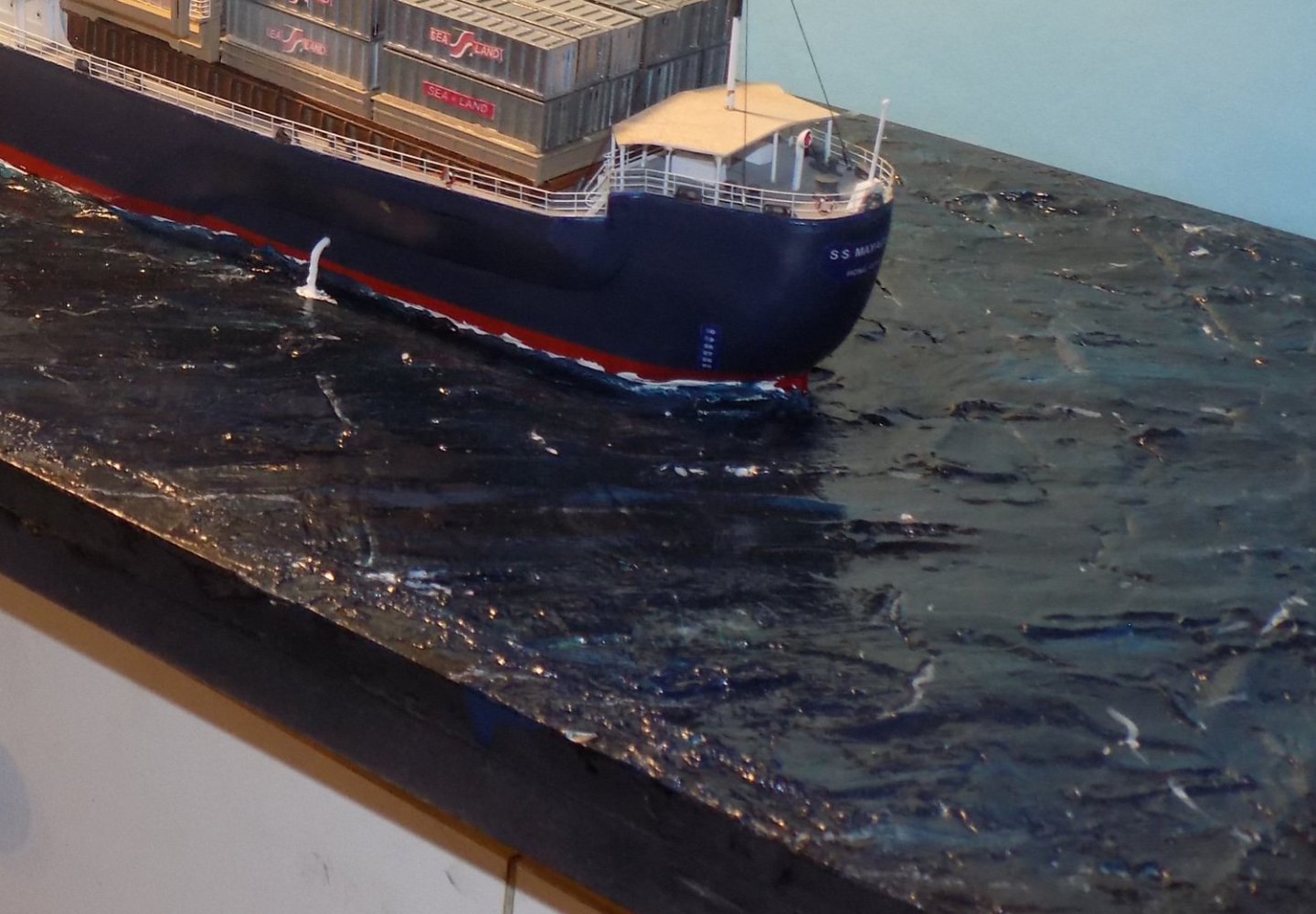
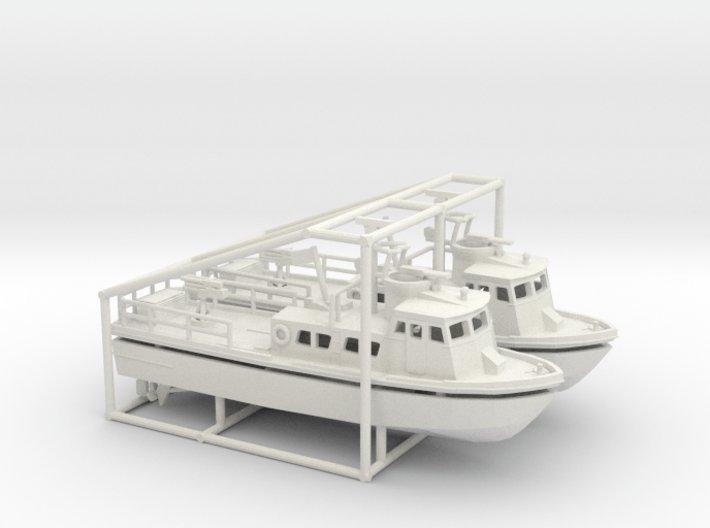
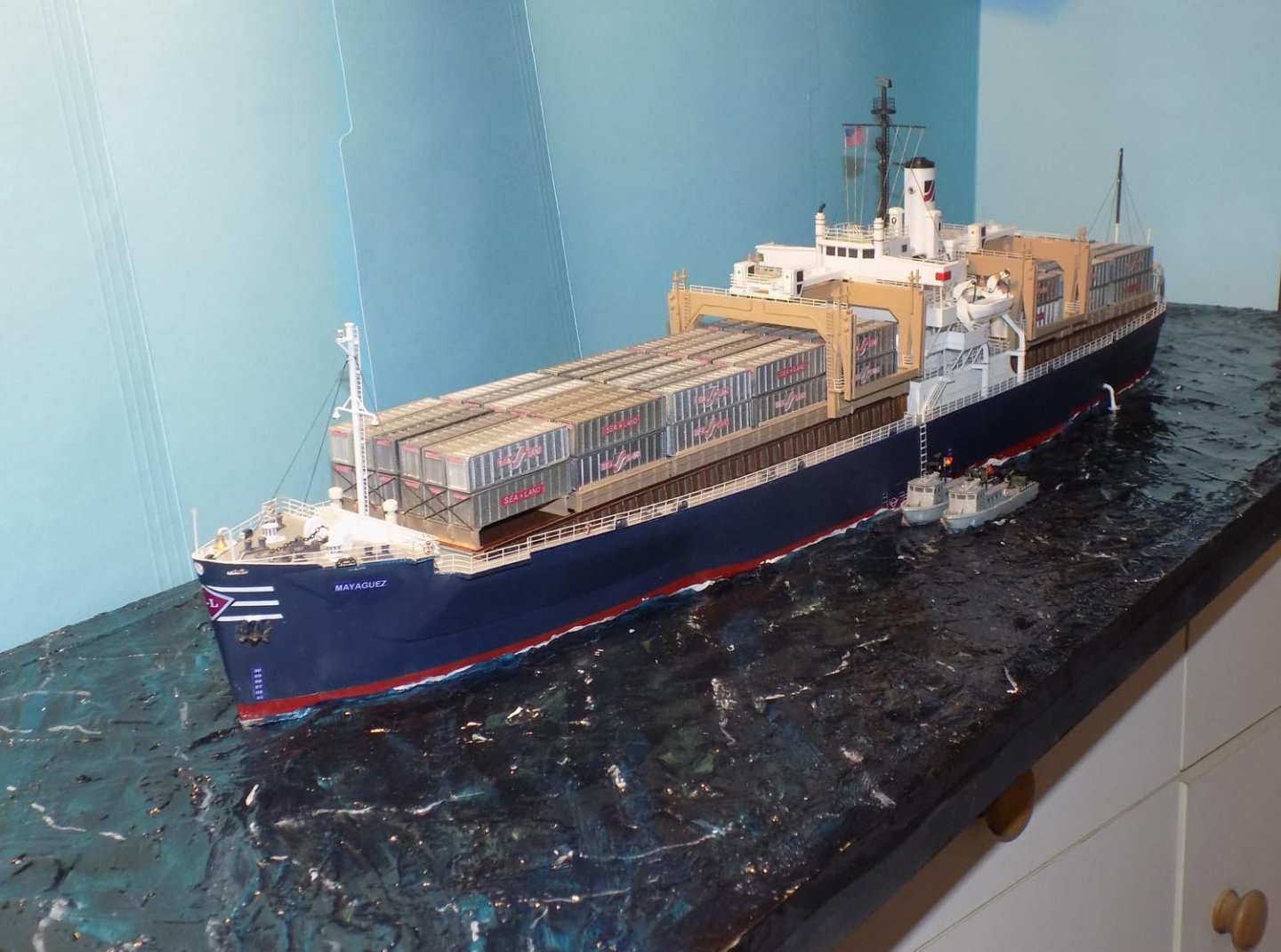
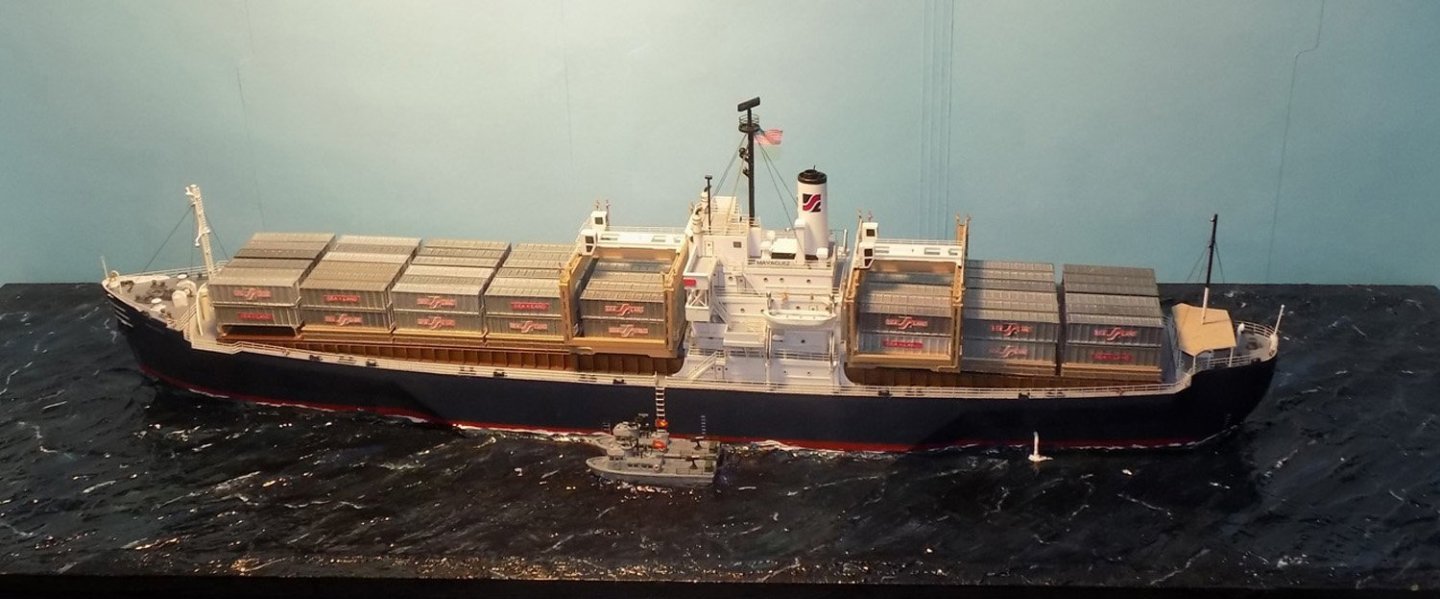
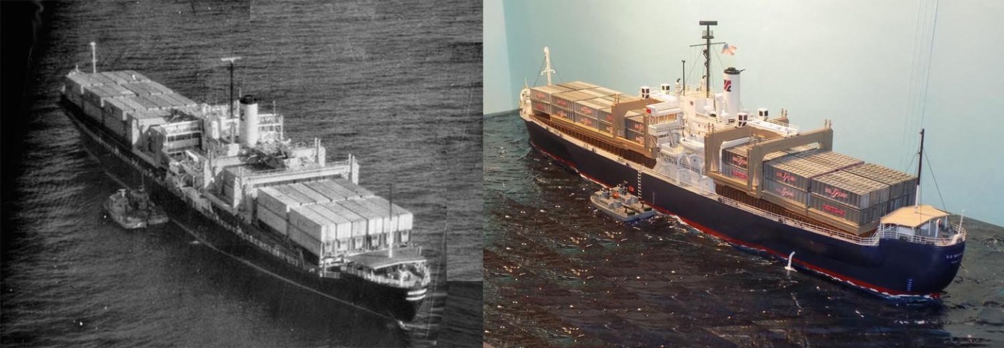
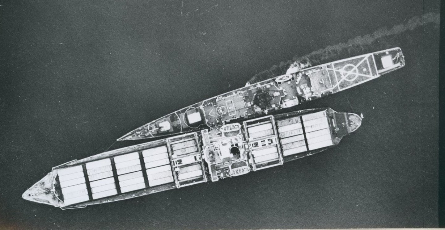
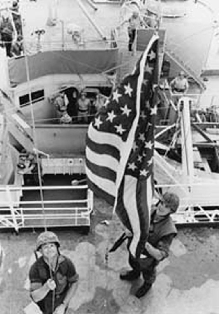
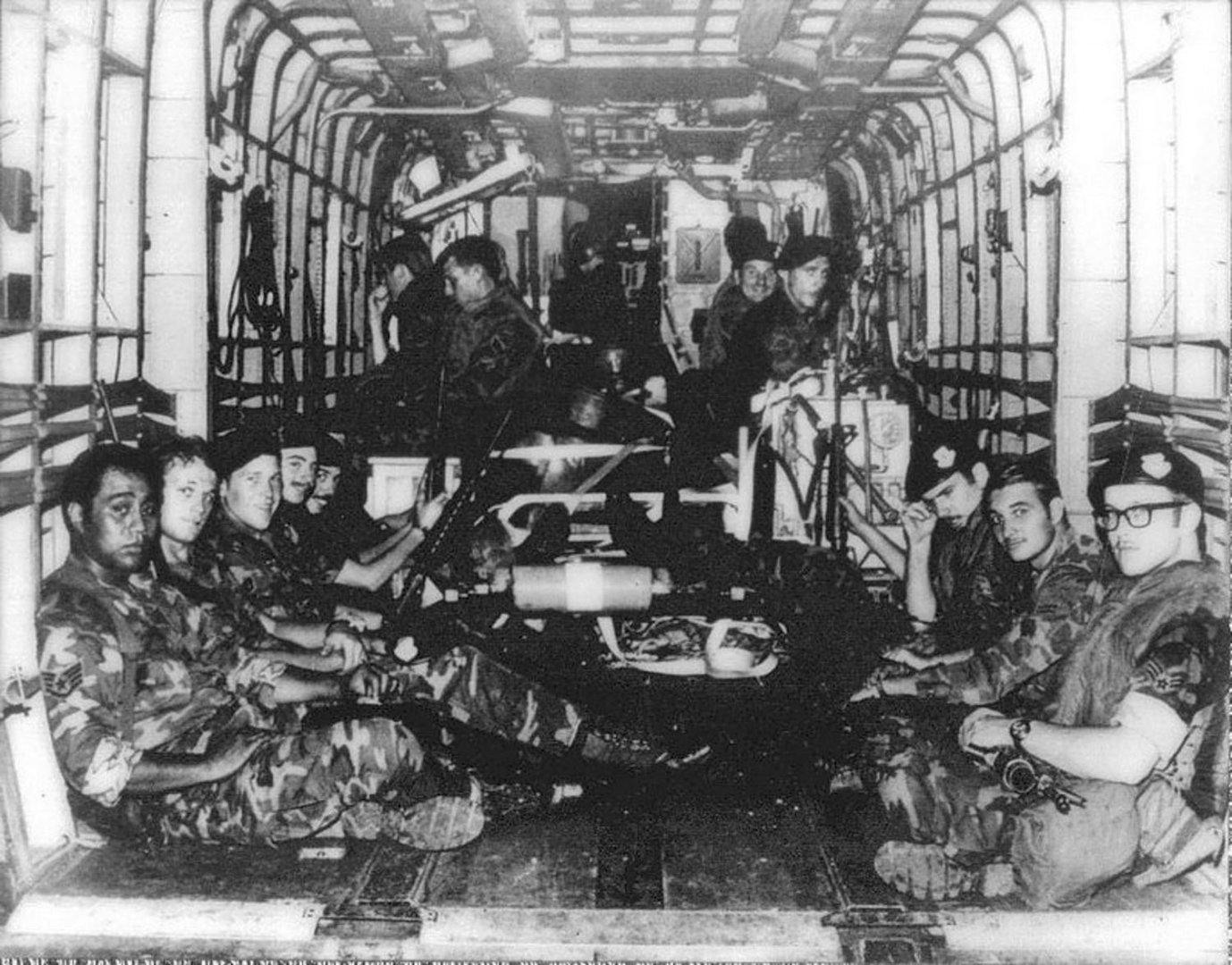
Hi again to all, and thanks as always for the likes and compliments. This will be the last segment of the build log, although I plan to edit it down a bit and turn it into an article for the Nautical Research Journal. Although all ships have their own stories, the history of the Mayaguez is more exciting and tragic than most, so I will go into it in a bit more detail than usual for a build log. Some of it was set out in the first segment of the log, leaving off with the capture of the ship. Here, as they say, is the rest of the story. Let’s go back to that fateful day of May 12, 1975. The SS Mayaguez is heading from Hong Kong to Sattahip in Thailand carrying 107 containers of routine commercial items and 77 containers for the US military of non-military supplies such as mail and PX items. Although in a recognized and heavily travelled sea lane, she was only 6 miles from the small island of Koh Tang, claimed by both Cambodia and Vietnam. The communist Khmer Rouge government of Cambodia, which had recently captured power, started enforcing a 12 mile limit off the island and had already seized a number of ships from several countries and had fired on several others. Despite this, the American military command had not issued any warnings to commercial ships to avoid the area. At 2:18 in the afternoon the captain was called to the bridge by the third mate on watch. A gunboat carrying a red flag was approaching fast. A few seconds later there was a burst of machine gun fire over the bow. Captain Miller decided to continue to see what they would do. A sailor on the gunboat raised an RPG to his shoulder and fired over the forecastle. Unable to outrun them the captain stopped the ship and it was boarded by more than a dozen soldiers from two small Cambodian armed boats. Here is a close up photo of one of the boats which was used to detail these elements on the model. The text on the side reads in part: “A Cambodian gunboat nestles alongside the American container ship SS. Mayaguez off Koh Tang Island as its Cambodian Khmer Rouge crew take over the U.S. freighter. This picture was made by one of the crew. The crew was swiftly taken captive and the ship directed to the nearby Koh Tang Island. The Captain and radio operator did an extraordinary job of getting off a series of SOS messages with the ship’s status and position. These were relayed to US military command in the Phillipines and an Orion P-3 reconnaissance aircraft flew over, but was fired on. Despite the danger, overflights were continuous after that, although repeatedly fired on. In Washington an emergency meeting of the National Security Agency was taking place between President Gerald Ford and his team of well-known advisors, Henry Kissinger, Nelson Rockefeller, Donald Rumsfeld, Brent Scowcroft, William Colby, James Schlesinger, and the full Joint Chiefs of Staff. With that lineup it is not surprising that the final decision was to make a “strong statement” that would be recognized by the Koreans, the Chinese, and the American public. The reaction of the Khmer Rouge was impossible to calculate and that of the ship’s crew was not important. American naval elements including the aircraft carrier USS Coral Sea and the frigate USS Holt were directed to steam to the area and await further orders. Over the next two days American jets from nearby bases sank several Cambodian gunboats but failed to prevent the crew being taken off the ship onto a fishing boat and ferried to Koh Tang Island. The ship itself was not taken into a Cambodian port, but that was mostly because the Captain exaggerated the depth of the hull and said the radar would not work, so the ship would ground. Meanwhile, Marines and other personnel from several bases were assembled nearby by helicopter and also told to stand by. Tragically, during the moves a helicopter crashed, taking the lives of these 23 USAF Security Police and the flight crewmen pictured here. This helicopter crash would not be the last. Back on the model the ship was complete and had to be set into its seascape. I will not go into detail here as to my method for sculpting and painting a sea. I have set it down in my build logs of the USS/SS Leviathan and the whaleboat James B Colgate. In fact, I did not photograph this part of the build of this model. Here, though, is a photo from the Leviathan build of the Plaster of Paris sea with waves and swells molded in with a damp sponge. The same method was used, but since photos show a calm sea and the ship was to be pictured at anchor after being captured, the surface was only lightly textured and only very small patches of foam were shown around the hull. One thing that I have found that increases the realistic look of a model far beyond its small size is the waste water discharge towards the stern of the ship. I made this by bending a small length of styrene rod over a candle flame. After trimming to length it was inserted into small holes in the hull and the plaster sea. The rod was textured with gel cyano dabbed on with a toothpick, heavier at the lower end where the stream would have broken up a bit. Then it was colored with flat white acrylic paint along with the small disturbance on the ocean’s surface. With some additional research it was discovered that the Cambodian gunboats were US made “Patrol Craft Fast” PCFs. Nicknamed “Swift Boats” they had been used in the rivers and coastal areas of Vietnam and also given to the Cambodians when they were our allies during that fight. An Internet search turned up a low resolution plan of the boats so I was started planning to carve and detail two of them for the diorama. This would not have been easy with a scale length just over two inches each. I then turned to Shapeways, Inc. to see if their designers had something that could be used as a starting point. To my happy surprise there was a set of two Fast Boats already in the right scale. They were molded in fairly smooth frosted plastic with the topsides molded separately from the lower hull. After cutting away the sprue framework the sections were separated and the interior was found to be filled with unhardened resin powder. This was removed and the topsides glued down to the hull. The propellers and rudders were removed as were the stern railings which were too thick. After sanding the boats were painted light grey before detailing. The guns on the stern deck and on top of the wheelhouse were painted, as were their mounts. Life rings were added from my spares box along with hull numbers. The stern railings were replaced with PE trimmed to size and the boats were finished with small paper flags painted with the flag of communist Kampuchea, a yellow temple on a red field. Hollows were cut into the plaster sea and the boats set in with a bit of plaster to fill any gaps. Paint and gloss finish melded them into the diorama. After a few touch-ups of paint the model was complete and ready for delivery to the museum at the US Merchant Marine Academy in Kings Point, NY. So here is a side-by-side comparison of the finished model with the photograph that started it all. I think that I achieved a “compelling evocation of the actual ship.” Others must think the same, because the model was honored with the Jim Roberts’ Craftsmanship Award at the 2022 Northeast Joint Clubs Show. My gratitude goes out to all of the judges. To finish, we return to the tragic and poignant Mayaguez Incident. By the evening of May 14 the ship had been seized and the crew had been taken off to Koh Tang Island. President Johnson authorized military action and several Kampuchean gunboats have been sunk. Naval ships and Marine units were being hurried to the area so a “strong statement” could be made. By the early morning hours of May 15 the pieces were in place and the order was given to seize back the ship and rescue the crew on Koh Tang Island. Approaching cautiously, the USS Holt came alongside the Mayaguez. At 06:13 in the morning, after a bombardment with tear gas, armed Marines in gas masks stormed the ship, only to find that it had been deserted. With no opposition, the American flag was once again raised above the bridge. At about the same time a communique from the Kampuchean government was broadcast which blamed the US for the incident and described the Mayaguez as a “CIA spy ship”, but which announced that both the ship and the crew were being released. This was received in Washington an hour later, but was initially disbelieved. Nonetheless, it was true and the crew was put on a captured fishing trawler and released. However, confirmation of this was not established until several hours later. Without this confirmation the assault on Koh Tang Island went ahead. Unfortunately, there were two major pieces of information that President Johnson and the Marines did not have. The first was that during the previous day the crew had all been moved from Koh Tang Island to nearby Koh Rong Sanloem Island. This was observed by American planes, but it was still believed that some of the crew were on Koh Tang. The second was that the Khmer Rouge had a much larger and more heavily armed force on Koh Tang which was meant to defend against the Vietnamese who also claimed the island. In the early morning hours of May 15 eight large helicopters, mostly CH-53 Sea Stallions, with 175 Marines began arriving at Koh Tang. Of these, three were shot down and two became disabled from mechanical problems. Nonetheless they landed 109 troops on three landing zones. This aerial photo shows two of the downed helicopters on East Beach. A running gun battle across the island continued throughout the day, even after the release of the Mayaquez’ crew was confirmed. By mid-afternoon the order to withdraw was given and the rest of the day was spent in several attempts to extract the landing force, with additional helicopters shot down and more US troops killed and wounded. This continued into the night, with confusion abounding amid the increasing fog of war. Ultimately, the bodies of a number of Marines and four live troops were left behind after all the others were evacuated. The Khmer Rouge, angered at the deaths aboard the gunboats that had been sunk and the 20 or so troops killed on Koh Tang, ultimately executed all four. The final US death toll for the unnecessary assault on Koh Tang was 18 troops killed and 50 wounded. Although the Mayaguez Incident did not occur in Vietnam, it is commonly referred to as the last battle of the Vietnam War. The names of the Marines and other personnel who were killed in combat are inscribed on the Vietnam Veterans Memorial wall. This does not include the 23 USAF Security Police and flight crew who were killed in the helicopter crash during the troop movements prior to combat. They were not so honored. What lessons can be taken away from this poignant tragedy? Not many, other than that assaults by slow, loud, fragile helicopters are rarely successful – see, e.g., the Iranian hostage rescue mission, ‘Blackhawk Down’ in Mogadishu, and even the successful killing of Osama Bin Laden. Here’s hoping that it may never be necessary to mount another such military action. Be well Dan


-
Hi Cisco - Very nice progress on the hull planking. You should end up with a nice, well-faired appearance. One small point - you said you had 'messed up' your butt joint spacing and that you took out some planks already applied. There was no need to do so. As I understand it, the 4 or 5-step planking patterns ONLY apply to deck planking. There were so many hull ribs, and so close together, that butt joints could land almost anywhere. Of course you would not want two butt joints next to each other, but there is not, and cannot be, any strict mathematical stagger to the joints on such a curved surface. For the deck, the beams were much further apart at a consistent distance and the surface was relatively flat, so a regimented pattern was possible. If you have some time, and can find the books, I highly recommend "Building the Wooden Fighting Ship" by Dodds and Moore, which describes the process with many excellent drawings and illustrations. Also, an easy, inexpensive, and enjoyable read is "Wooden Boats" by Michael Ruhlman, which is the story of his time at the Benjamin & Gannon shipyard on Martha's Vineyard where they still build wooden boats the old fashioned way. Best of success. I am looking forward to seeing your work next April in New London. Dan
-
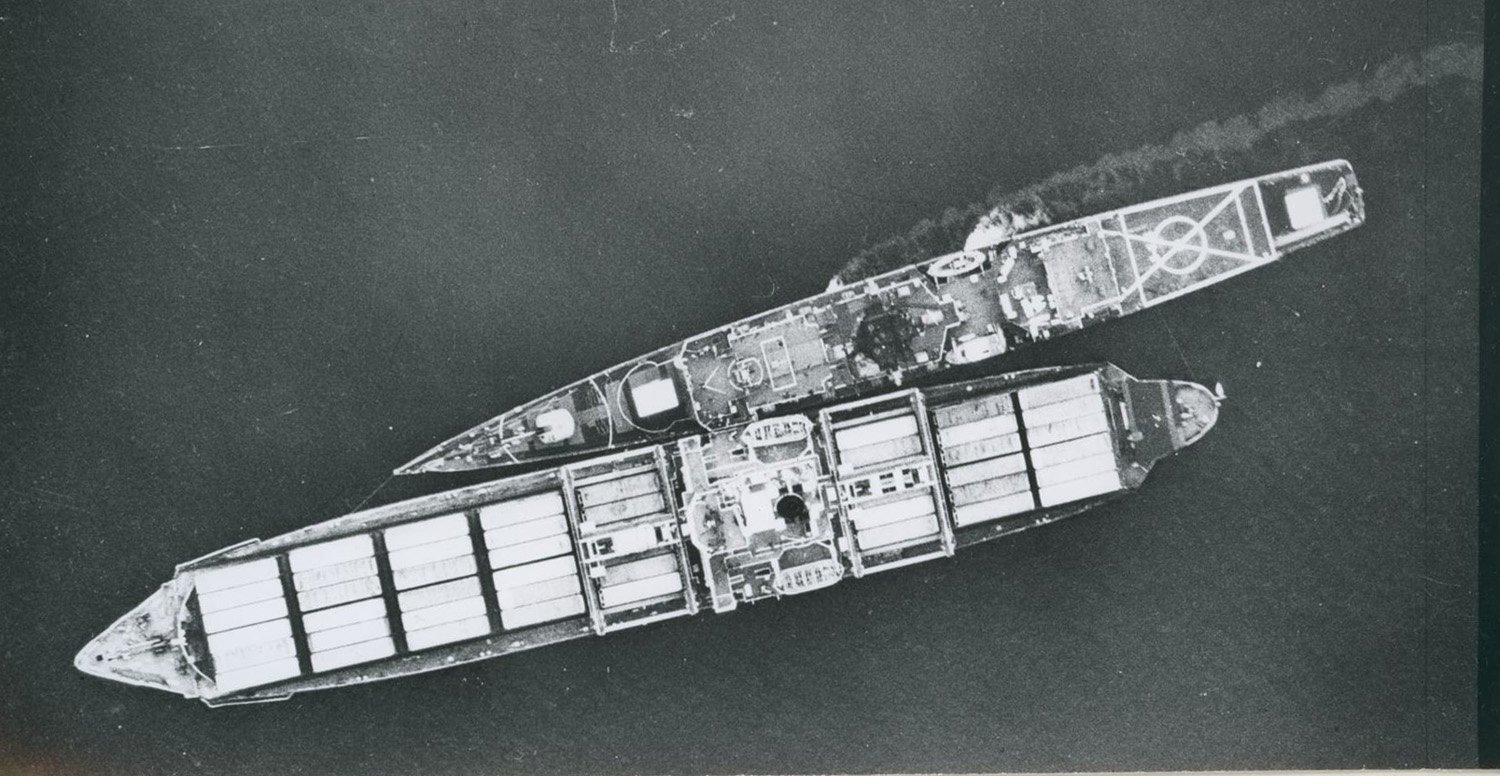
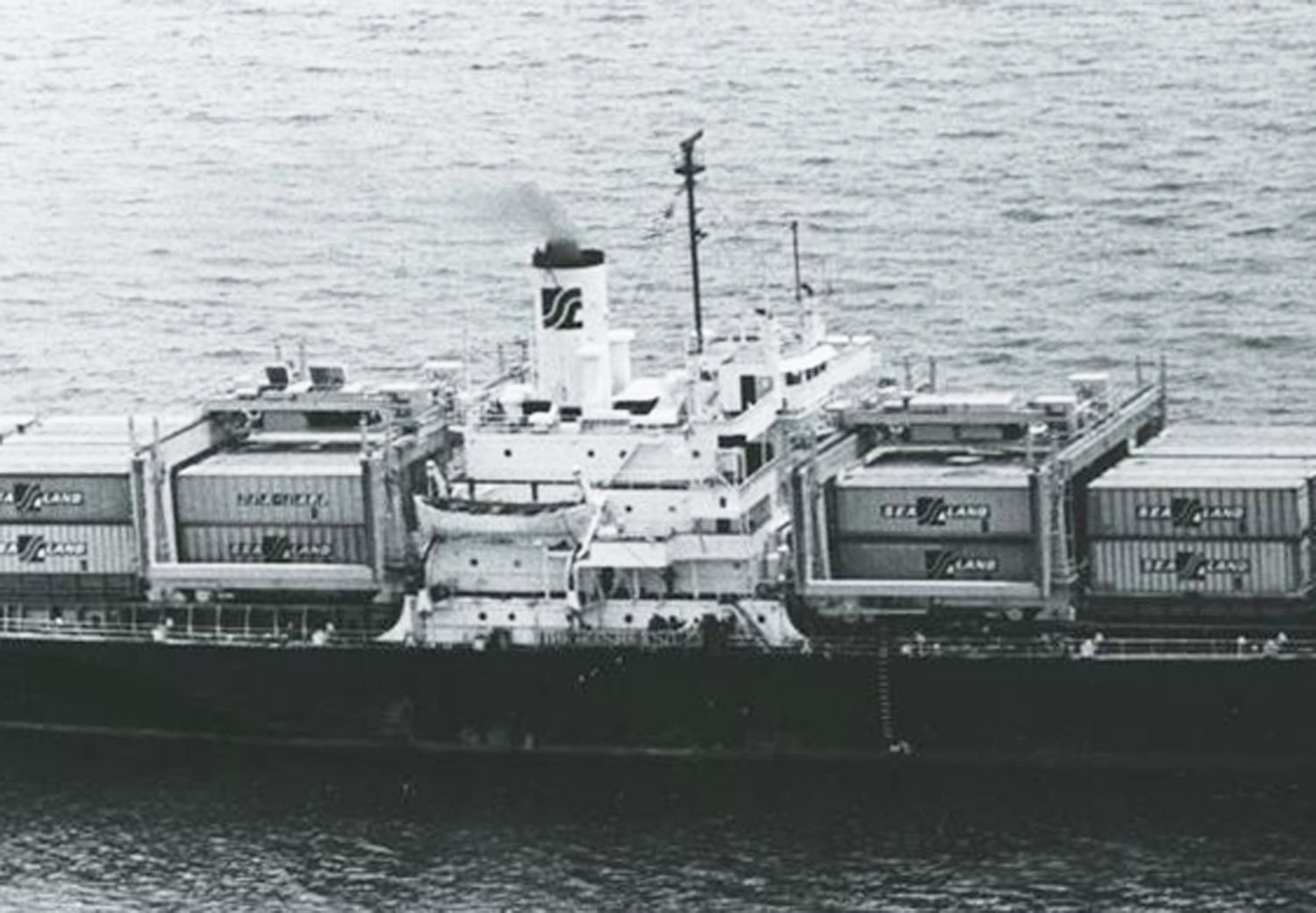
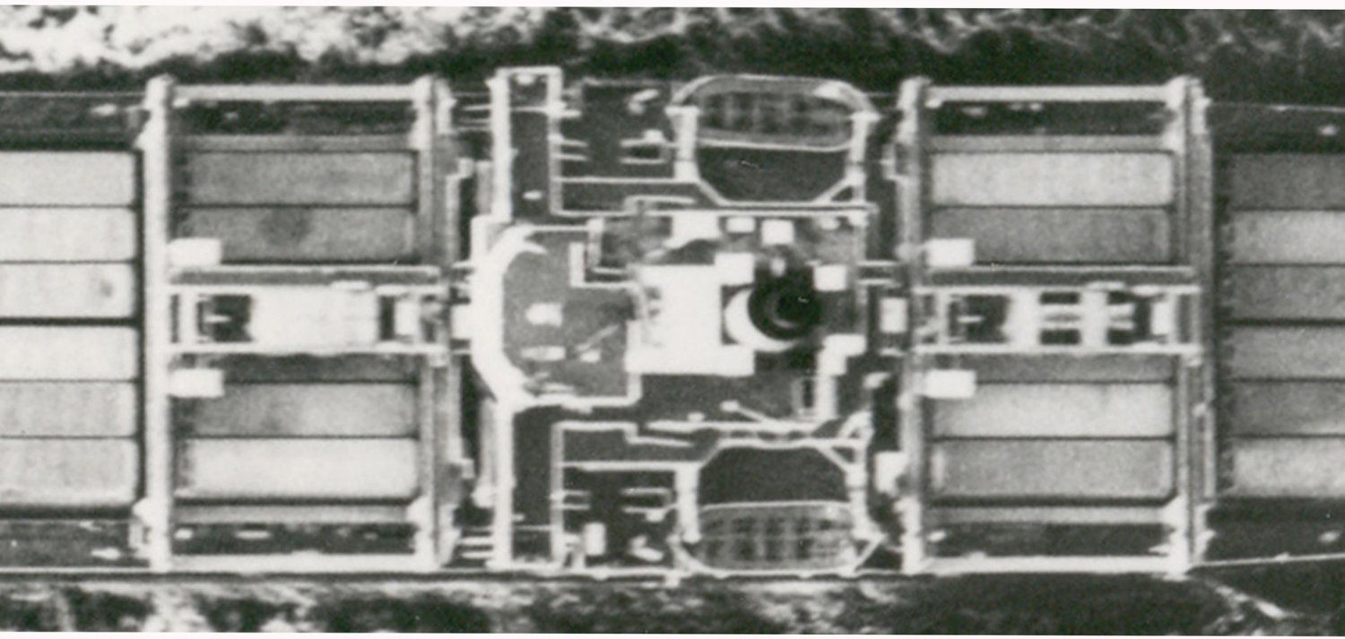
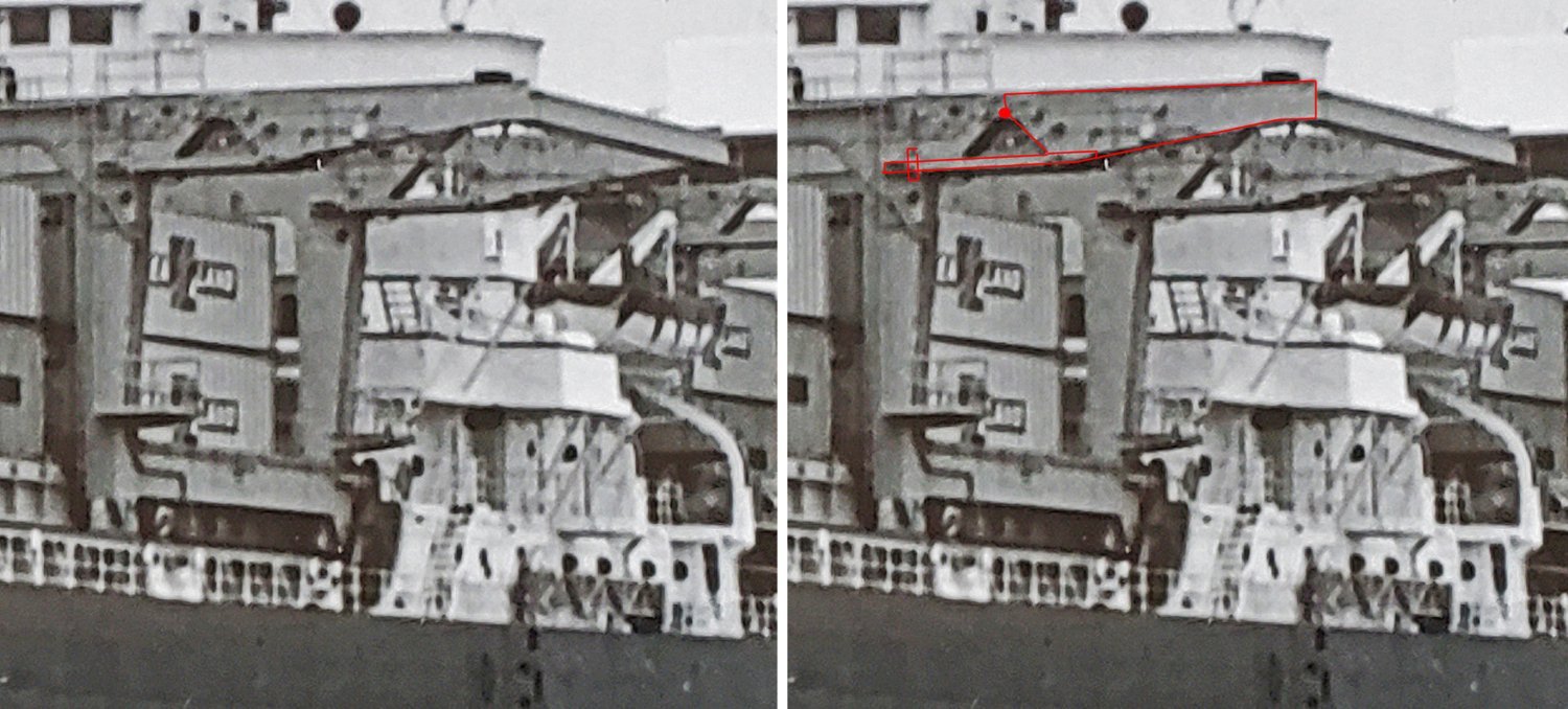
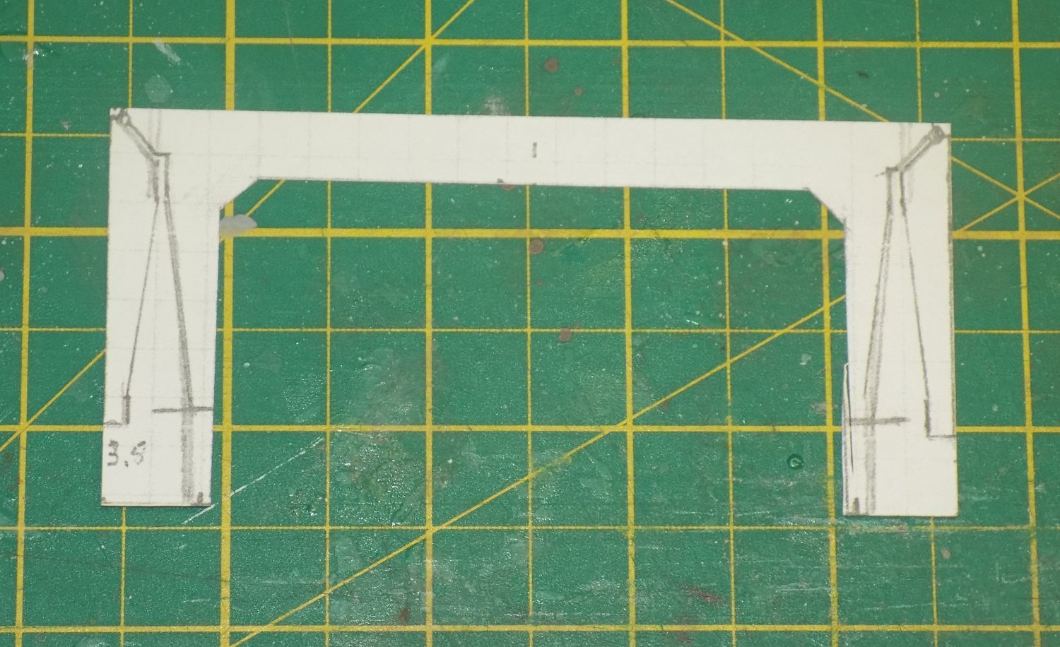
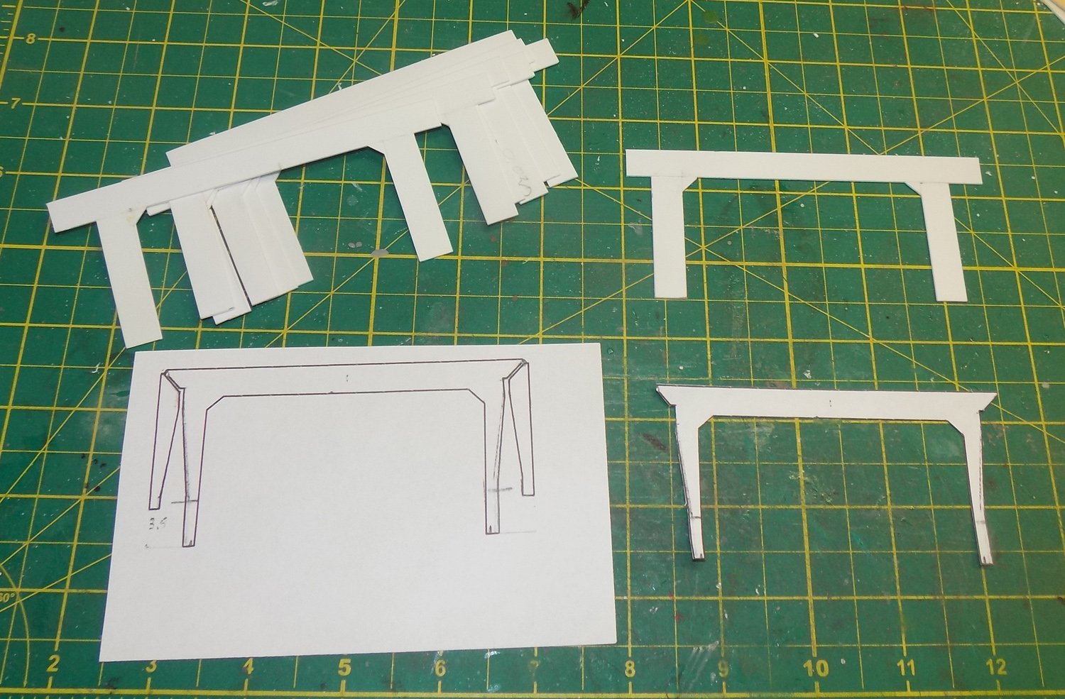
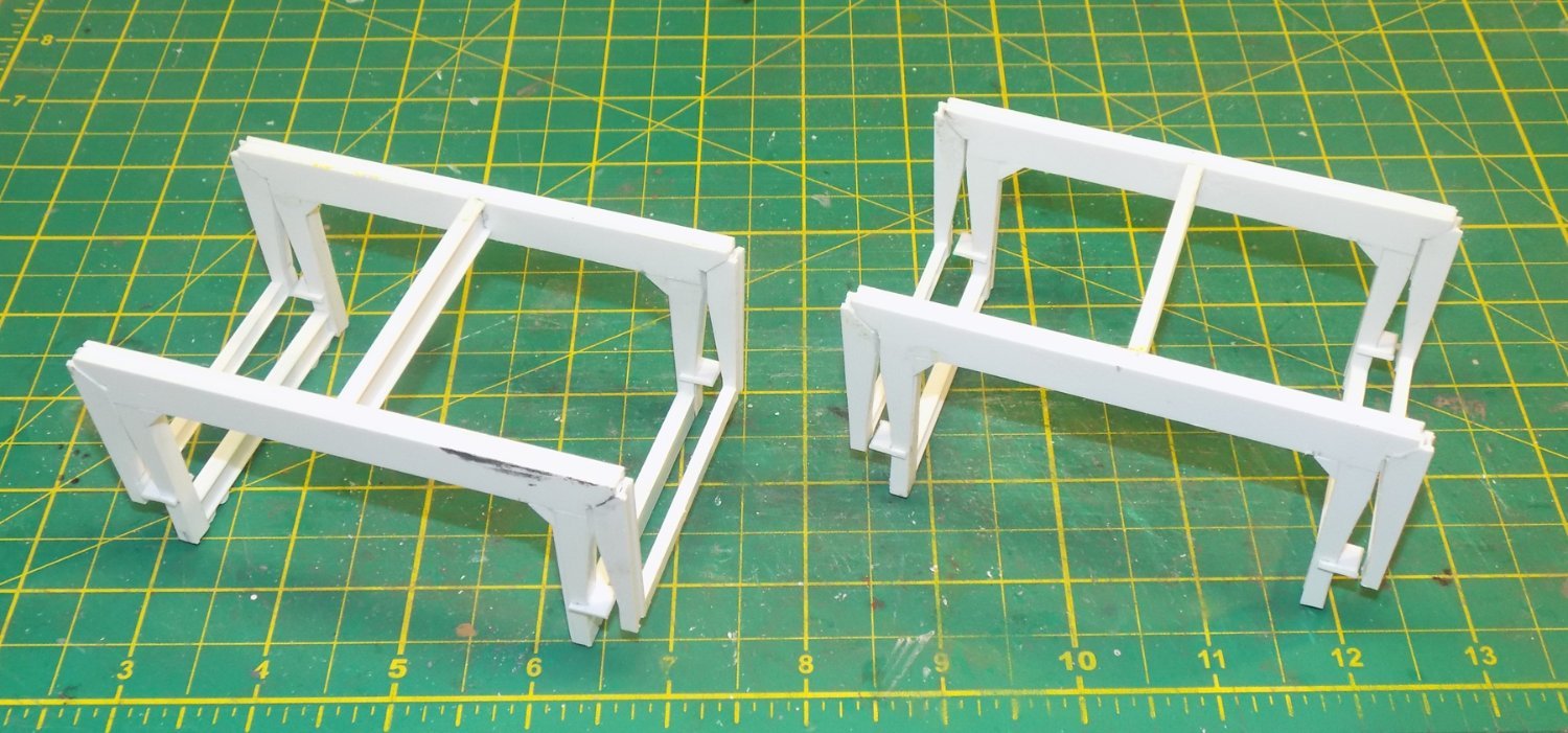
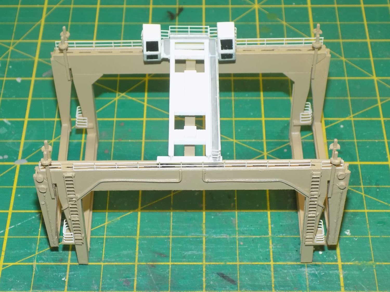
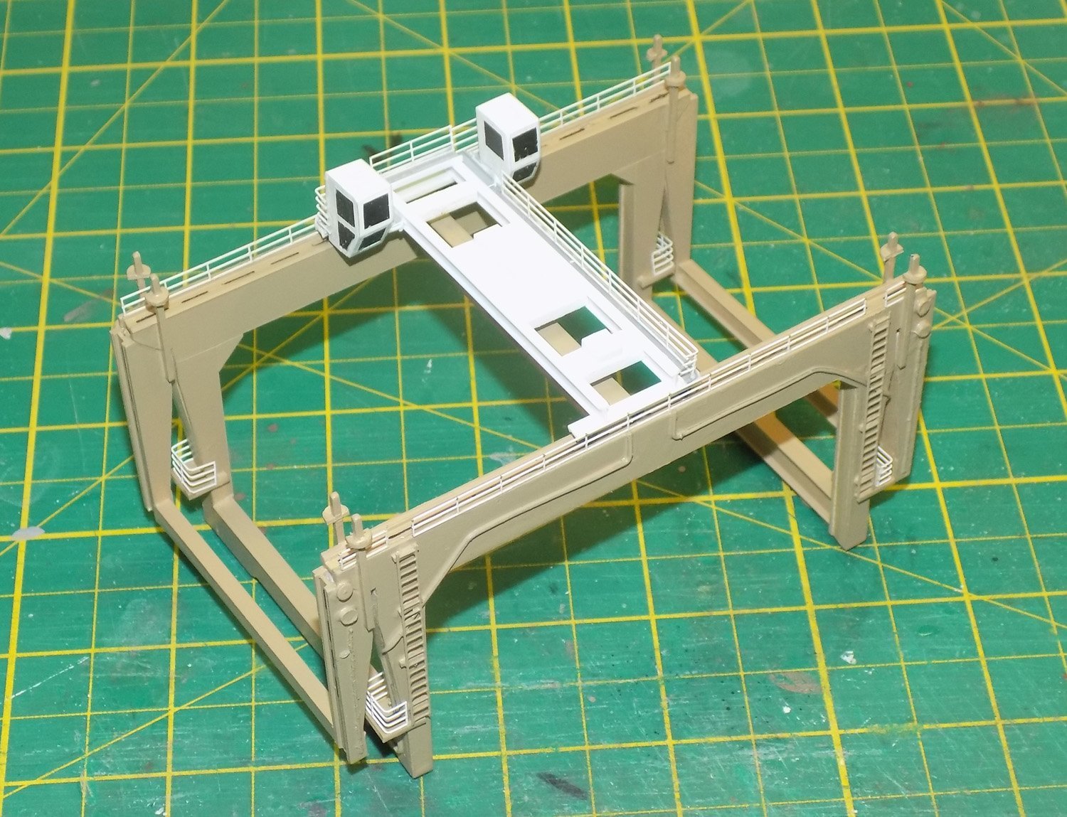
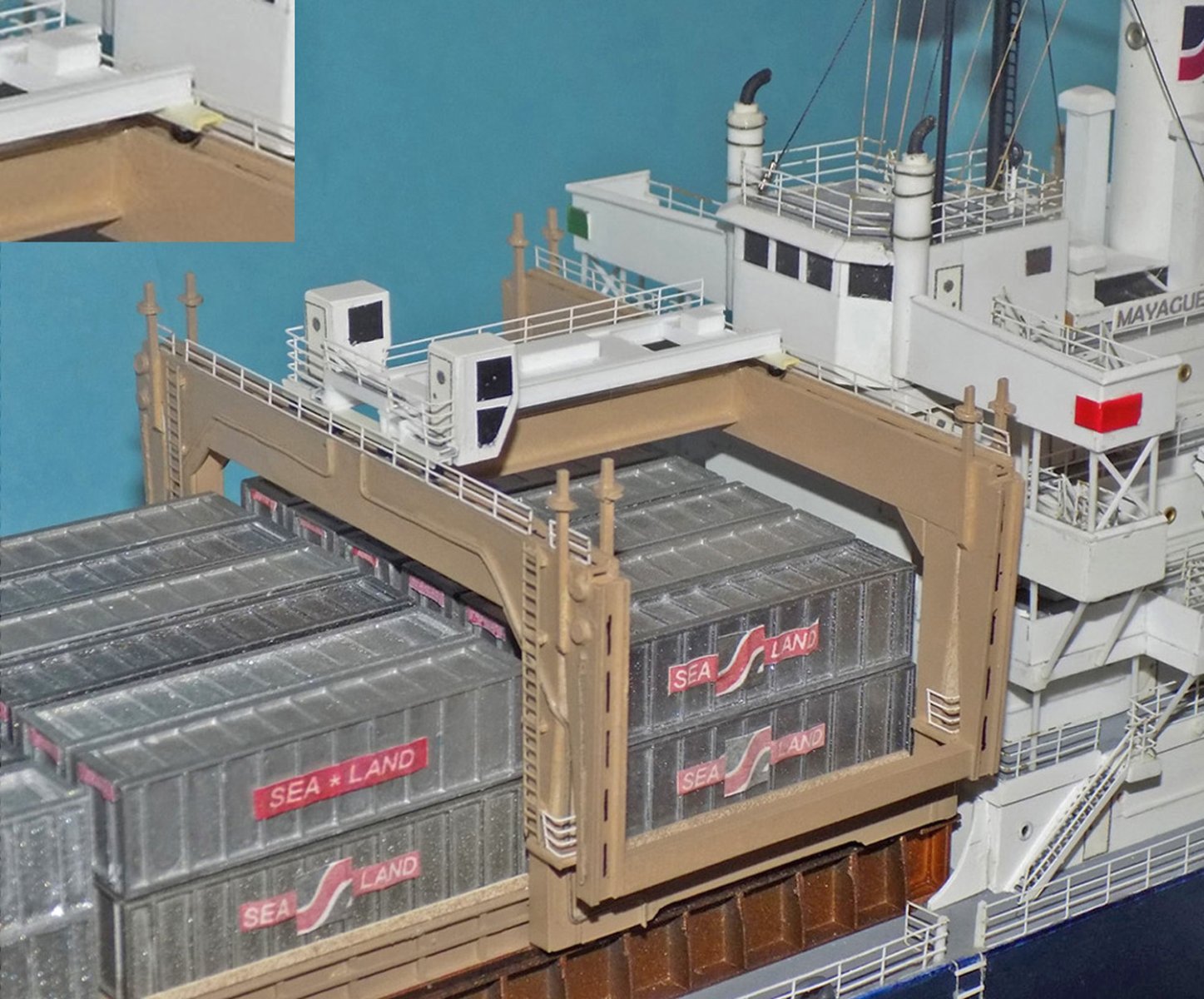
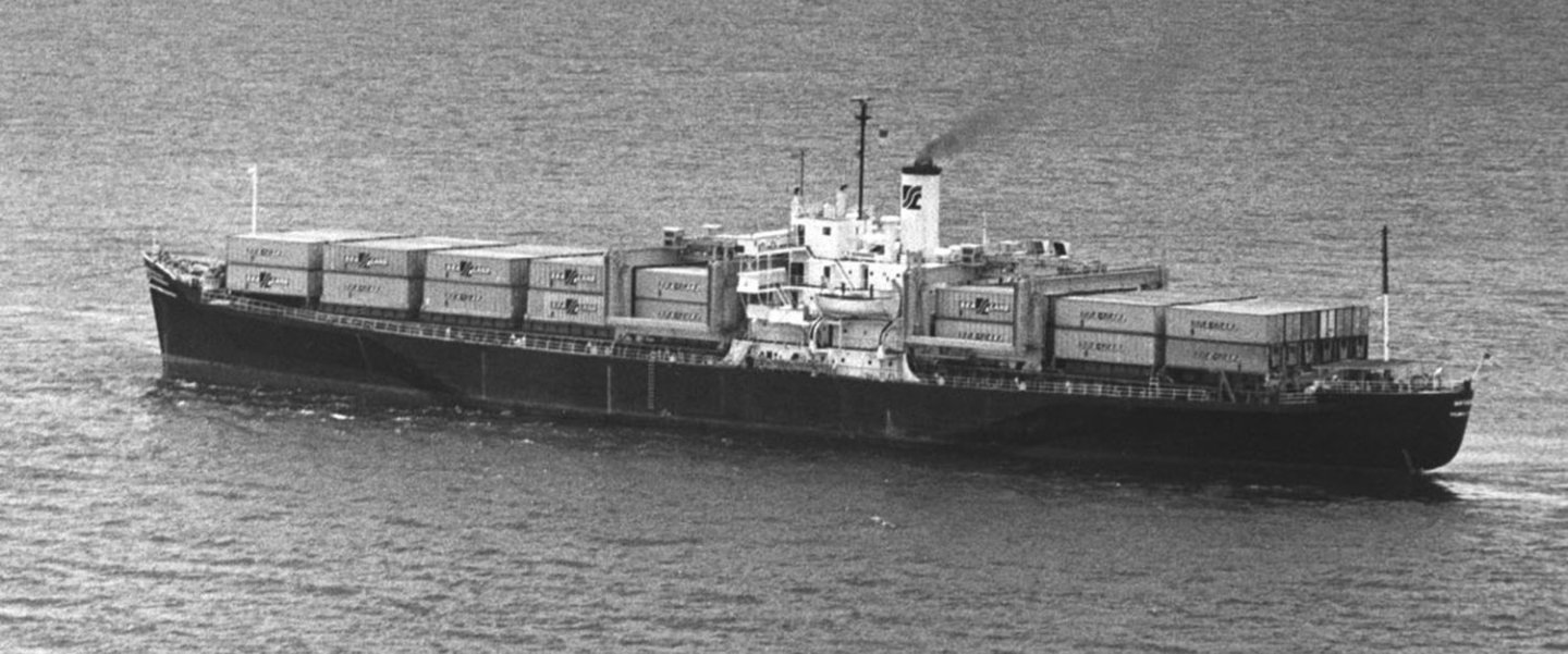
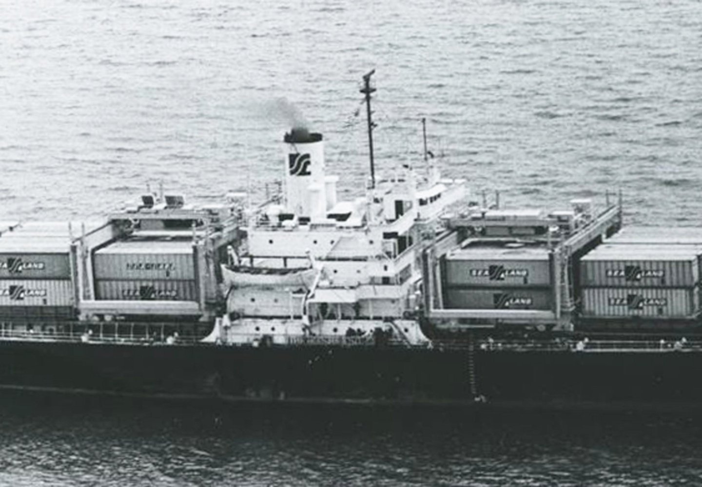
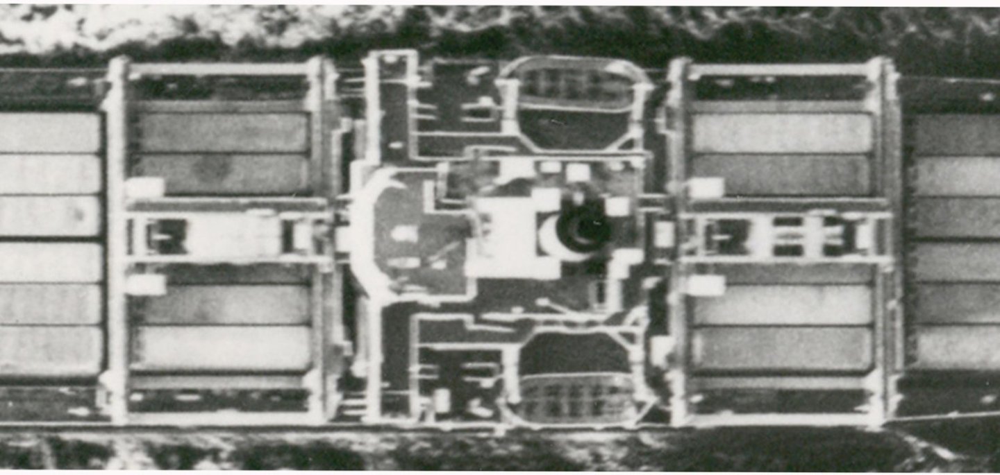
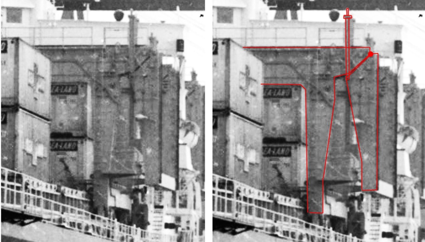
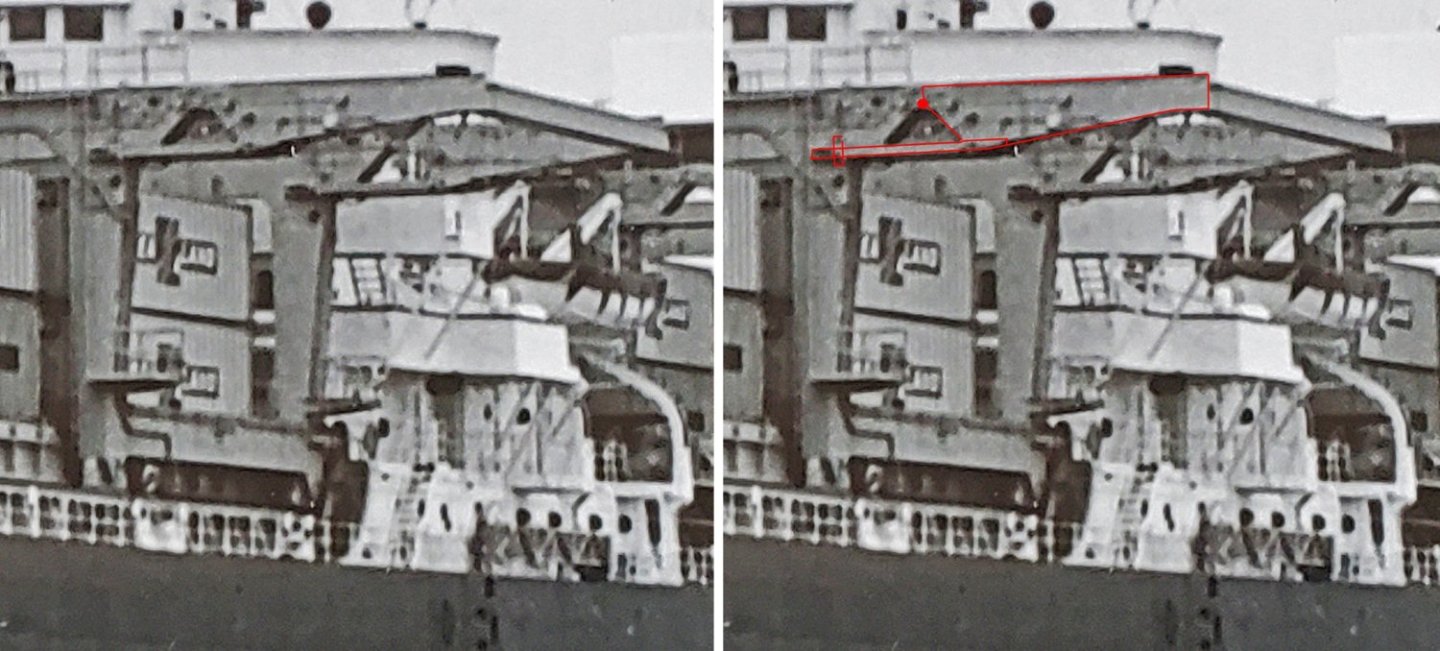
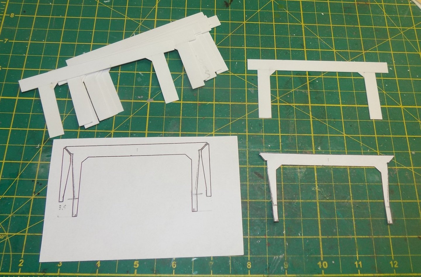
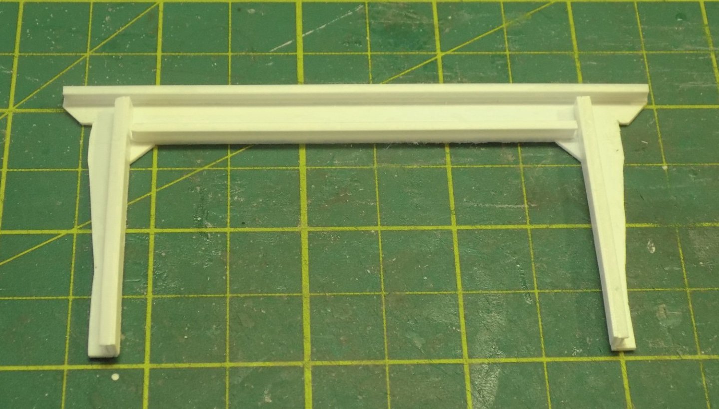
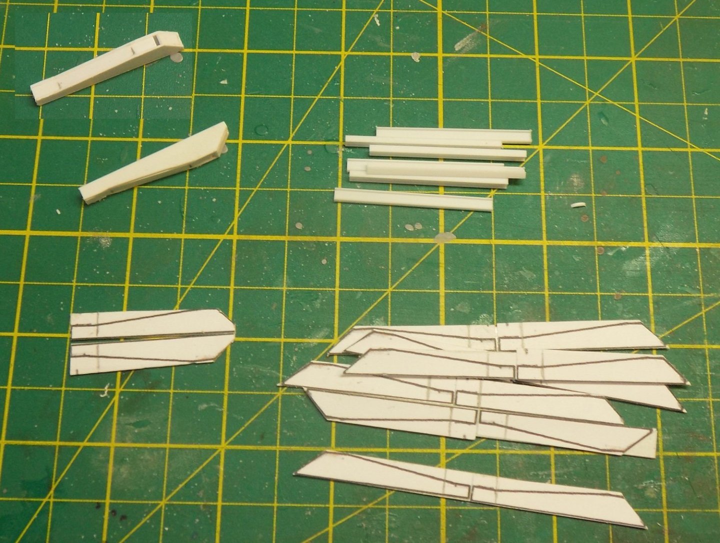
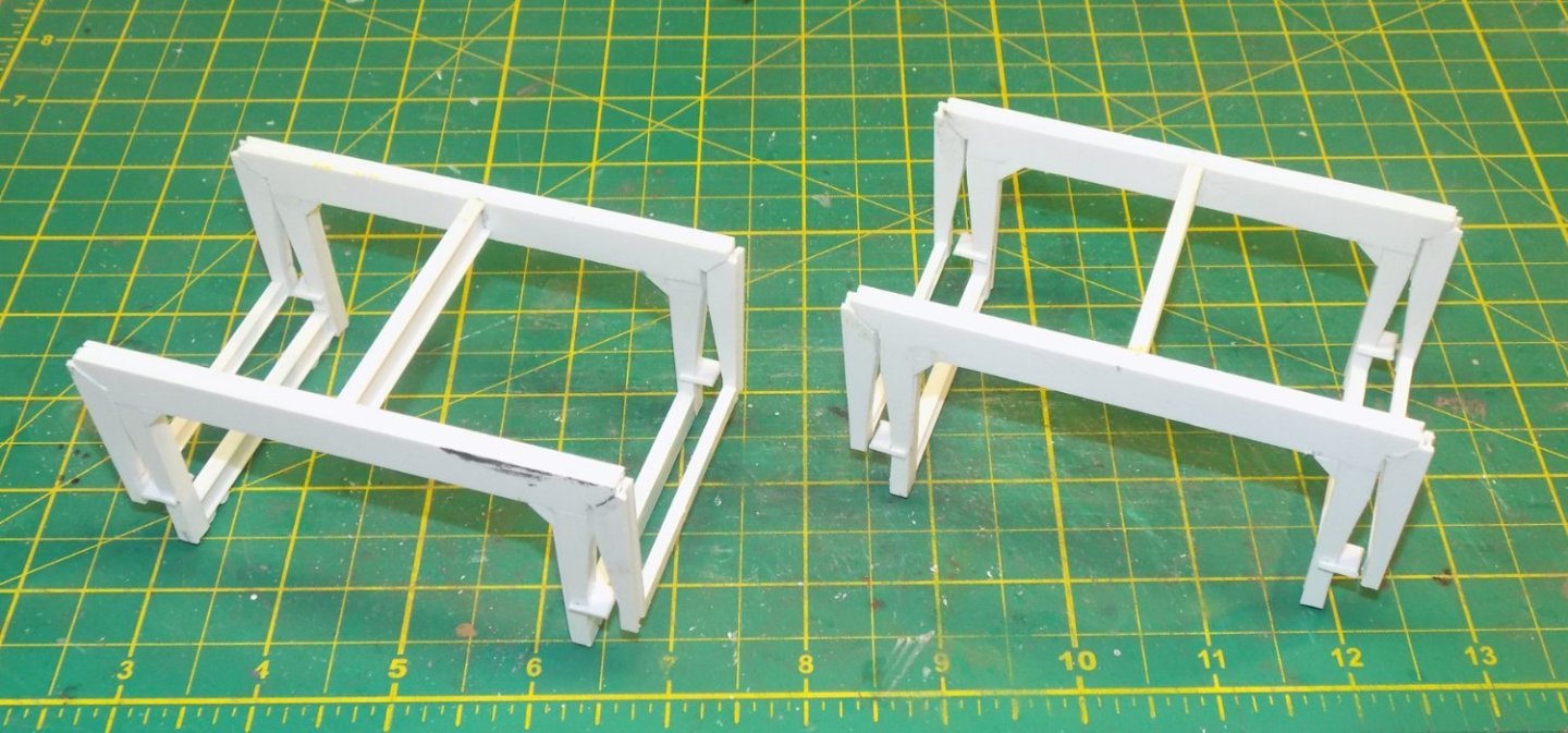
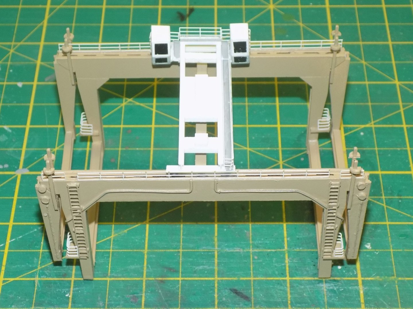
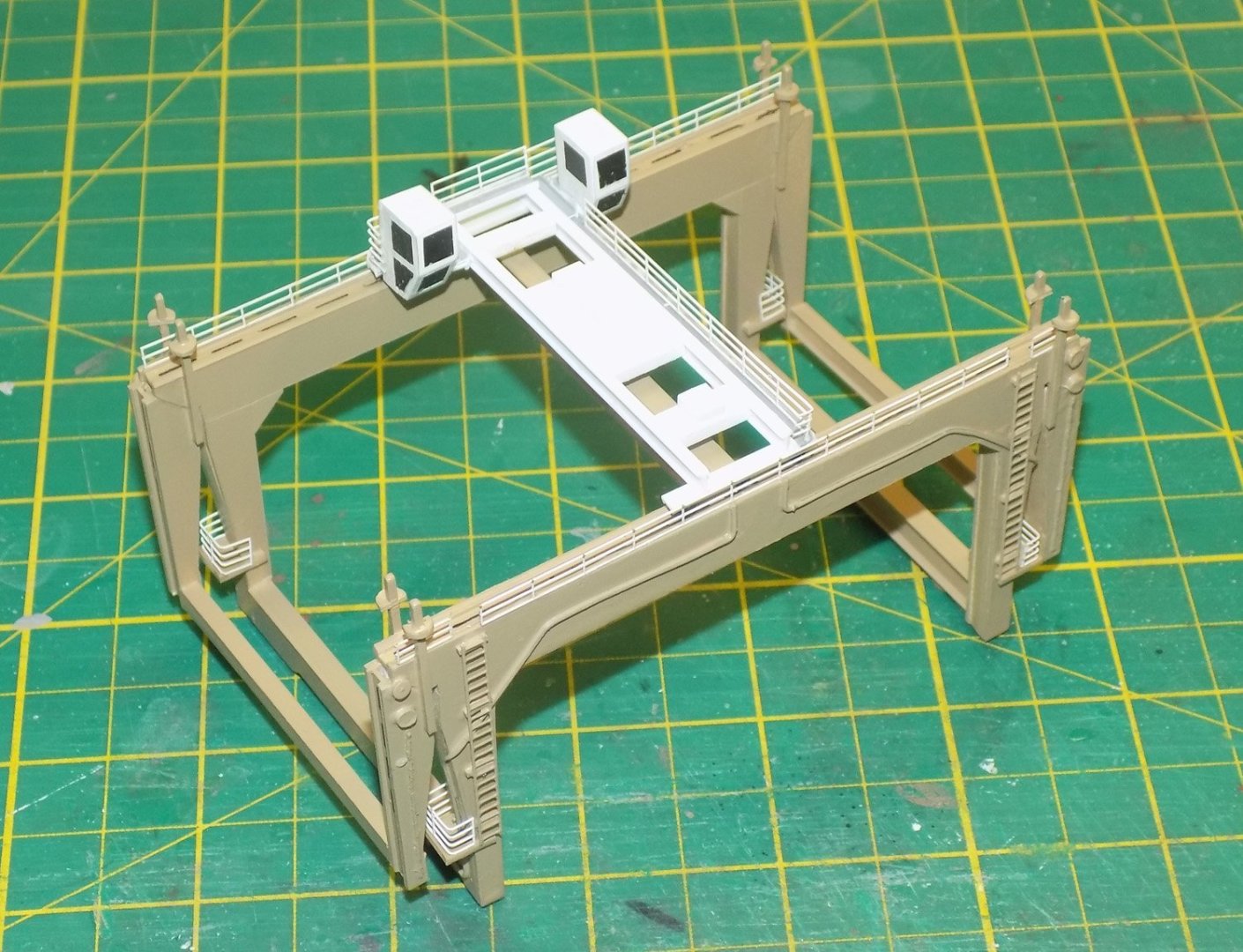
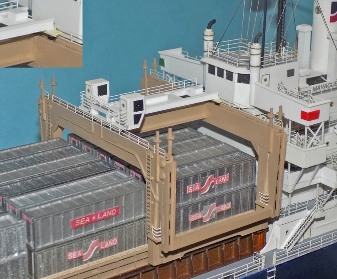
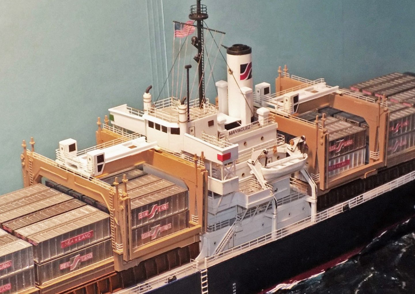
Hello again to all who are following this build. Sorry to say that it has been almost a year since my last post, but life has a way of interfering with my literary efforts. I’m happy to say that most of my health issues have resolved, leaving me with just the usual arthritic knees and a creaking hip replacement. At 72 this is to be expected, I suppose. As they say, it’s better than the alternative. But back to the model - - The build log left off with the ship completed – hull, superstructure, and 96 containers on deck. The only remaining major structures to build were the two rolling cranes that loaded and unloaded the 35’ long containers. Here is an overall photo of the ship at sea with the cranes set on their rails immediately forward and aft of the superstructure. In close-up you can see how they straddle the blocks of containers. The strong framework extends athwartships to the limits of the deck with a winch assembly on top that rolls side to side to lift and move the containers. From overhead the overall layout of the cranes can be seen. Obviously, they have to have at least 35’ between the vertical “U” shaped ends so the containers can move outboard without hindrance. From the photo it is obvious that there is not much clearance, so my cranes had to be built to reflect these tight tolerances. Once again the lack of plans of any kind was a bit of a problem. The layout and exact shapes of the several components of the cranes had to be deduced from the photographs. To tease these out from the blurry black and white photos was the hardest photo interpretation task of the entire build. Look at only the left side of the two images below. This is as good as it got. After much head scratching and comparing them to each other and to the many other less detailed photos, I was able to draw outlines of the pieces with a reasonable degree of confidence. These were drawn in red on the photos Note that the hinge between the central gallows piece and the movable wing piece must be located below the top of the gallows, otherwise they will not fit together with the tops aligned. I located this where the red dot is, although there is no fitting to be seen on the outside at this point. Also, I concluded that the vertical posts seen in the upper photo must be attached to the wing piece since they rotate to horizontal in the lower photos. I have no direct proof, but I think that they must be some part of a locking mechanism that holds the wing up when extended. With the shapes decided, rightly or not, I cut a piece of thick card stock so the bottoms of the inner vertical edges just cleared the container stacks and rested just outside of the crane guides on the lower trestles. From there the shapes of the gallows was drawn in and then the shapes of the wings. After much erasing and redrawing, I had shapes that fit all of the parameters and tolerances that I needed. This drawing was finalized, then scanned and copied onto blank paper. Since there were four gallows pieces, two for each crane, I needed eight identical pieces cut from plastic for the sides. I first made up the eight blanks with rectangular pieces of 0.040” styrene welded to each other with thin plastic cement. A simple jig made sure that the inner dimensions between the uprights was consistent and correct. Small triangles were added to the inner corners as reinforcements as seen in the photos. Then each gallows drawing was cut from the paper and spray mounted to the plastic blank. Careful cutting with a sharp blade guided by a metal rule gave me the gallows piece in plastic. The paper was easily removed with a drop of Goo Gone, a mild solvent. To make up the thickness of the gallows components four ¼” I-beams were glued to the inner face of one of the gallows pieces. This not only gave me a consistent thickness, but reinforced the joints between the sheet styrene pieces, rather than relying only on the welding action of the plastic glue. In a bit of serendipity, using the I-beam across the top gave me a channel in the top that the rolling winches would be mounted on. Not shown - a second gallows piece was positioned over the I-beams and glued in place. The open sides were closed in with lengths of styrene strip the width of the I-beam between the two gallows sides. The wing pieces were made in a similar fashion. Sixteen wing piece paper outlines were printed out, mounted on sheet styrene, and cut out. An I-beam was fitted to the straight side of one and a second wing piece glued to the beam to match the first. In the upper left the sides of the assembly can be seen after being filled in with styrene strip. Five I-beams of different sizes were all cut to the same length, just a bit longer than the 35’ containers. A central large beam and two smaller ones at the lower corners connected two of the gallows to each other, forming a strong “U” that slid over the containers and rested on the lower trestles. Then four of the wing pieces were attached to the upper corners of the gallows and connected to each other with smaller I-beams. Small pieces of plastic were cut to fit around the lower legs of the gallows representing the control and observation platforms for the cranes. These assemblies were then detailed with the locking arms, ladders, piping for electric lines or water runoff (I never did figure out which), and some punched discs seen in the photographs. After painting them tan some black markings were drawn onto the winch channels, then railings were added to the tops of the gallows and around the control platforms. The winch assembly was put together from some two dozen pieces to build up a moveable platform to match, as best I could figure it out, the less than detailed photographs. I also had to use some additional common engineering sense for what had to be there, even if I couldn’t see it. There is a walkway only on the starboard side and behind the two winch control houses. The windows for the winch houses were cut from black decal film and carefully applied. Here is the crane mounted on the lower trestles. In this view you can see the paper applique doors on the winch control houses which had to be there, though I never saw them. In the enlarged insert, the small black beads that represent the rollers that would allow the winch to run outboard along the channels on top of the gallows. Similar small wheels were mounted under the legs of the crane to allow it to roll along the lower trestle to pick up containers from any location on the ship. So here are the pair of cranes, as fitted to the ship, which is now complete. The final installment of this build log will focus on the ocean setting and the Cambodian gunboats that captured the ship. I hope to get it out soon. Until then, stay safe and well. Dan

-
Hi Marc - Lovely work on the figures. They should set off the stern quite impressively. As for the sails, read through my build of the Queen Anne's Revenge. I did a lot of experimenting to make the billowed sails, although not to the extreme that you want to take them, given how they look in the drawing. The scale is quite different, so the materials will have to be substituted, but there should be some techniques there you can profitably use. Looking forward to watching her top hamper rise. Enjoy the vacation Dan
- 2,696 replies
-
- 5
-
-
-
- heller
- soleil royal
- (and 9 more)