shipmodel
-
Posts
941 -
Joined
-
Last visited
Content Type
Profiles
Forums
Gallery
Events
Everything posted by shipmodel
-
 By George, you've done it. Bravo! Dan
 -
Good work. Now your deadeyes match the level of realism of the rest of your excellent work. Glad to be of some help. Dan
- 1,350 replies
-
- 4
-

-
- constitution
- model shipways
- (and 1 more)
-
Hi Tom - Rob is right - deadeyes can be defined as a movable part of the standing rigging. Other similar items would be the lacing between hearts that hold the stays to their collars. As such, they would not move much, but still have to move a little to allow them to be unlaced and tensioned. My understanding of true Stockholm tar is that once dry it would waterproof the line, but not be movable. To protect these few movable lines, I believe that they used an oil formulation that would protect the line from salt water, but still be flexible. Some of the additional confusion came in when deadeyes were used to tension steel cable shrouds. These did not stretch much at all, so they did not have to be re-tightened. Deadeye lanyards here could be permanently set up and tarred. Modeling books of the early 20th century incorporated what they saw, and not what might have been appropriate for the ship in its' time, and this misinformation was perpetuated. As for color - after looking over a number of reproduction and restored ships, all I can say for sure is that the colors vary pretty widely. I have always opted for a dark brown shade, a bit lighter than the black of the shrouds, but still a far cry from the tan of the running rigging. As always, though, the artistic choices are up to you. If you do choose to go darker, you should be OK with painting the lanyards with a Minwax stain. Try a few to see the color and intensity that you like. A 50/50 mix of Natural and Early American works for me. Dan
- 1,350 replies
-
- 1
-
-
- constitution
- model shipways
- (and 1 more)
-
Hi Tom - Your rigging is coming right along. Nice and clean. Will you be leaving the deadeye lanyards that pale grey color? I think that it is close to the color of those on the present ship, rigged with new rope, but may be a bit too light if you are trying to show her in early service. Also, and I know this is a bit of a nit to pick, but the correct spelling of your fitting is 'sheer pole', not 'shear pole'. The first refers to the curves of a ship's hull, the latter to a sharp, clean cut. Somehow they seem to get confused with each other from time to time. Only one letter, but there is a large difference, for example, between a house and a mouse. Keep up the good work Dan
- 1,350 replies
-
- 2
-
-
- constitution
- model shipways
- (and 1 more)
-
Hi Keith - Nice metalwork, as always, on the mast hoops. To get that aged look to the copper, without waiting, try heating them in a dry frying pan. They can take on a range of colors, from dull red/brown to almost black. This technique has been used on the protective copper plates for the hull, with good results. I believe that there is a discussion of this, and other copper darkening methods, in "Ship Modeler's Shop Notes, volume 1" published by the NRG. I also seem to recall others doing the same chemically, but with various fluids, including urine !! Hope one of them works for you. Dan
-
Hi Druxey - Yes, I have. It works well, but dries harder than the wood, since it is meant to be used on autos with metal or fiberglass surfaces. This makes it tricky to sand without dishing the wood around it. It feathers out nicely, but not much better than plaster or other fillers. Besides, I could only find it in a fairly large tin, and the last one I bought dried out before I could use it all. Ounce for ounce, of course, it is much less expensive than the Squadron putty. The other issue, on this model, is that the final paint color will be white. The red of Bondo is hard to hide without more coats of primer than I wanted to add at this stage of the hull finishing. A good idea, but not for this use this time. Dan
- 287 replies
-
- 5
-
-
- michelangelo
- ocean liner
- (and 1 more)
-
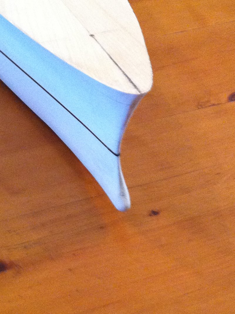
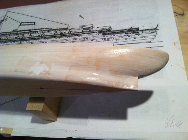
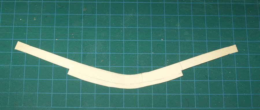
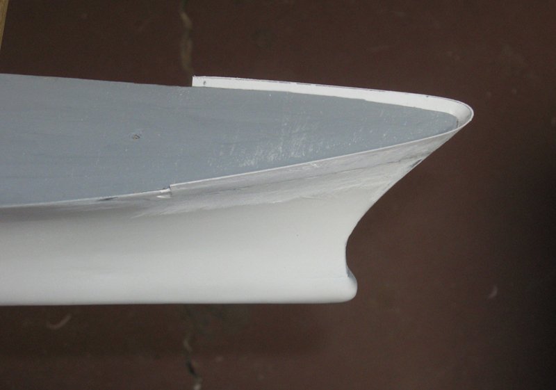
Hi all – Thanks for the conversations and the likes, as always. And thanks for looking in on my little diversion. It was an exercise in water sculpture, and reasonably successful, although I have a ways to go to make it that spray truly realistic. When the last installment ended, the hull had been glued up and shaped. The wood had been hardened, ready for final finishing. The next step was to bring the hull to a smooth surface, ready for the color coats. I first filled the pores of the wood with a slurry of plaster of paris. Here it is shortly after being painted on . Before it dried and became opaque I laid in a 1/16” wide strip of tape along the waterline as I did here on the Doria model. With the plaster dry it was gently sanded with a medium grit sanding sponge to smooth and fair the planes and surfaces. Here is how it looked at the bow. The waterline tape was removed at this point, but it left a very shallow but indelible depression along the length of the hull that will guide my painting later on. What followed were many refinements to those hull planes and surfaces, done with multiple layers of spray primer. The first several were of grey, sandable primer which filled in the deepest of the sanding scratches. For preference I use Krylon in the rattle can. It is fast-drying and builds up a sufficiently thick layer with only a few coats. But it is getting harder to find. Even Amazon runs out from time to time. I have found that the comparable product from Ace Hardware is almost identical. Medium and fine grit sanding sponges smoothed out the grey primer, then coats of white primer were sprayed on. This is a much different formulation, not just the color. It goes on thinner and dries to a much harder surface. Finer and finer grits of sandpaper were used, ending with a rubdown with a plastic scouring pad to burnish the surface. Much will be done to the hull, and it will get carved, drilled and sections ground out, but it was nice to have a smooth canvas to work on. The first addition to the hull was the bulwark at the bow. This has to be flared considerably to match the steep angle of the hull at the nose. To get this shape, I wrapped a wide strip of card stock around the bow and taped it in place, making sure that it lay tight and flat all around the bow. Where it rose above the deck, I penciled in a line. Using a flat piece of scrap as a spacer, a second line was drawn at the height of the finished bulwark. The card was removed and a third line was drawn, freehand, about ¼” below the deck line to account for where it will be attached to the hull. Several were made and discarded before one was acceptable. The finished template shape looked like this. This shape was cut out of a piece of 0.020” styrene sheet. I made sure to make the first cuts overlarge, then it was slowly refined by repeatedly offering it up to the desired location and trimming as needed. A shallow step was cut, carved, and ground into the hull and the piece laid in and secured with gel superglue. The edges were filled and faired with Squadron white putty. Here is the bow bulwark piece before final fairing into the hull. The difference in sheen tells me where the putty still needs more refining. The bulwark is still a bit oversize at the top edge, which will not be refined until the detailing process begins. This was my first time using Squadron putty. It is a solvent based gel which comes in a tube like toothpaste and is squeezed out in much the same way. Because it is solvent based it dries quickly, but the fumes are a bit harsh, so have some good ventilation where you work with it. The other problem is that it shrinks substantially as it dries. Some deep depressions had to have several layers applied before it built up enough to sand back to a smooth surface. Next, I work on the stern. Be well Dan

- 287 replies
-
- 16
-
-
- michelangelo
- ocean liner
- (and 1 more)
-
Patrick, Greg - yes, Bob deserves a gold medal. But all I can do is to give him full credit for such a perfect achievement. Druxey - I have always relied on the kindness of strangers . . . Dan
- 287 replies
-
- 5
-
-
- michelangelo
- ocean liner
- (and 1 more)
-
Also - I have been spending most of my time working on the second edition of the Queen Anne's Revenge. Click on the QAR link in my signature, below, and go all the way to the end for some progress photos. Dan
- 287 replies
-
- 5
-
-
- michelangelo
- ocean liner
- (and 1 more)
-
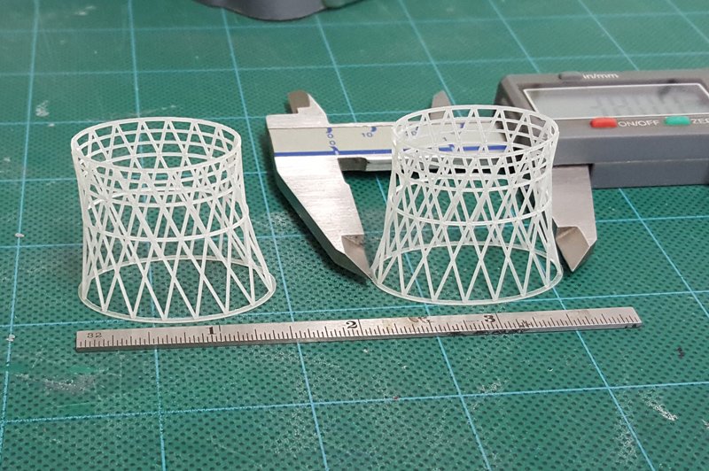
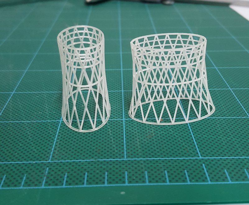
Hi all - Bob Marvin has come through in fine fashion, as has Shapeways. Here are photos of the funnel cages made with the 3-D printing process. I will get them in hand to examine at the New London conference, but they look great. Now I have to build the internal structures with a quality to match these pieces. Thanks, Bob. Dan
- 287 replies
-
- 14
-
-
- michelangelo
- ocean liner
- (and 1 more)
-
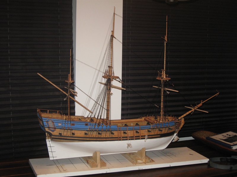
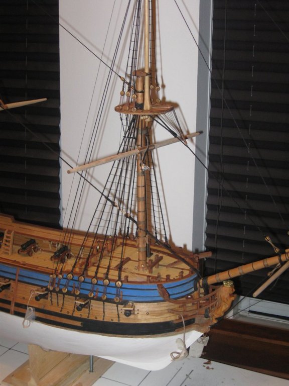
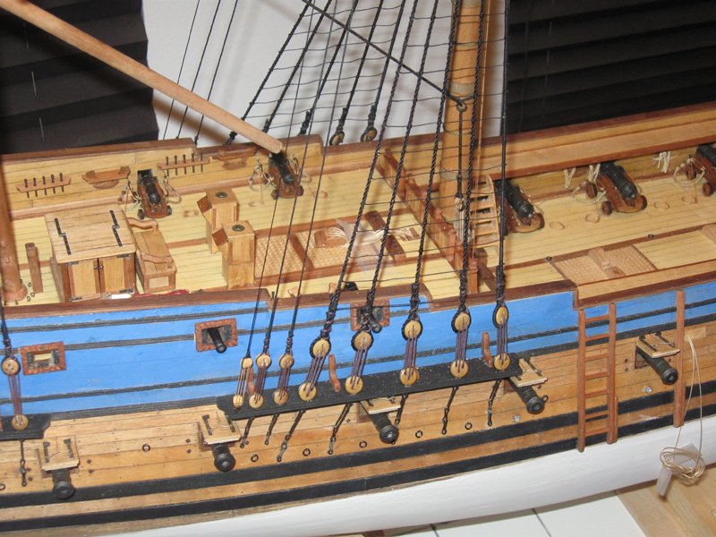
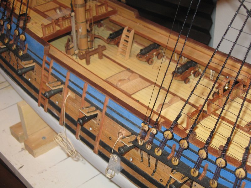
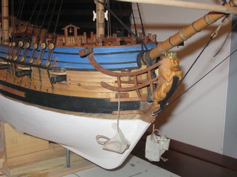
Hi all - As mentioned during the build of this model of the Queen Anne's Revenge, I have been tasked to do two models of the ship. One for each of the museum's locations - Raleigh and Beaufort. I have been working steadily on the second edition, but not done a build log, since almost all of the techniques used, and the results obtained, are identical. Below are some progress photos. The hull is complete and fitted out. The masts and all of the standing rigging is done. I am turning the spars as I listen to the Masters. The only significant technical difference is invisible. I had a good deal of trouble with the lower hull in the first model. Despite lots of glue, doweling, and wood hardening, there were some hairline cracks that developed between hull crescents caused by humidity changes that would not go away. To eliminate the problem, the entire lower hull of this model was fully planked and pegged. I have not had a repeat of the issue. Sharp eyes will note one or two differences between the two sisters. I took the waterline and wales up about 10mm to more closely match the profile of the Advice Prize plans, rather than Budriot's Mercure. It lays out much better for the headrails, hawse holes, and quarter badges. The museum requested that all of the guns, not just the port broadside, be run out, so they were set and rigged ready for combat. Finally, the underwater archaeologists have located some of the chain plates for the lower deadeyes. Rather than the solid straps found with other French ships of the period, they are metal loops and backing plates similar to those generally known on English ships. Accordingly, they were made up from iron wire and secured with nails into the hull. I will post some more when I get closer to completion. As always, feel free to comment, question, or critique it. Be well Dan
- 241 replies
-
- 13
-
-
- queen annes revenge
- pirate
- (and 2 more)
-
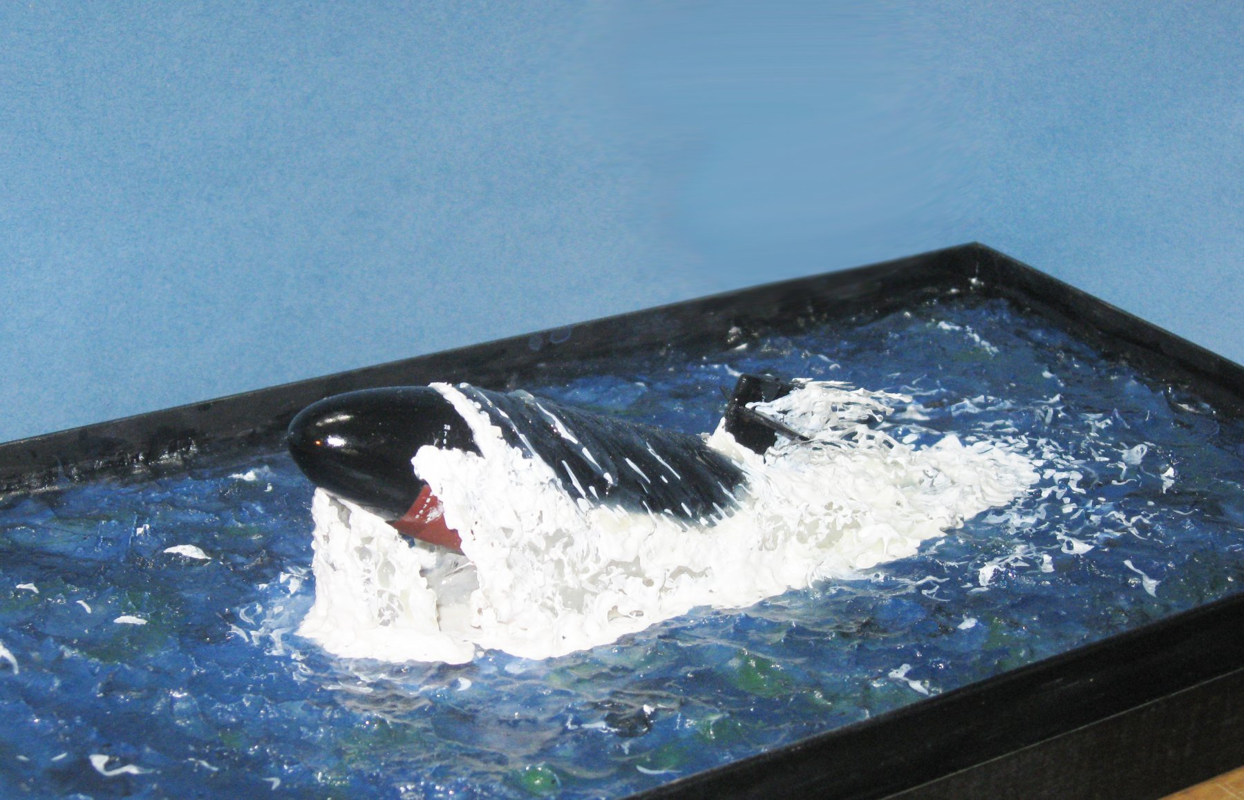
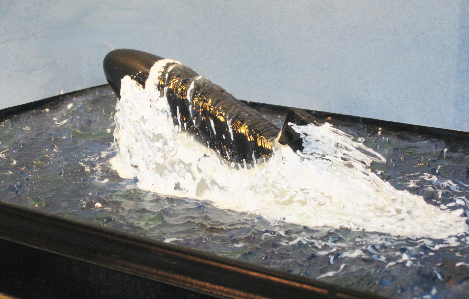
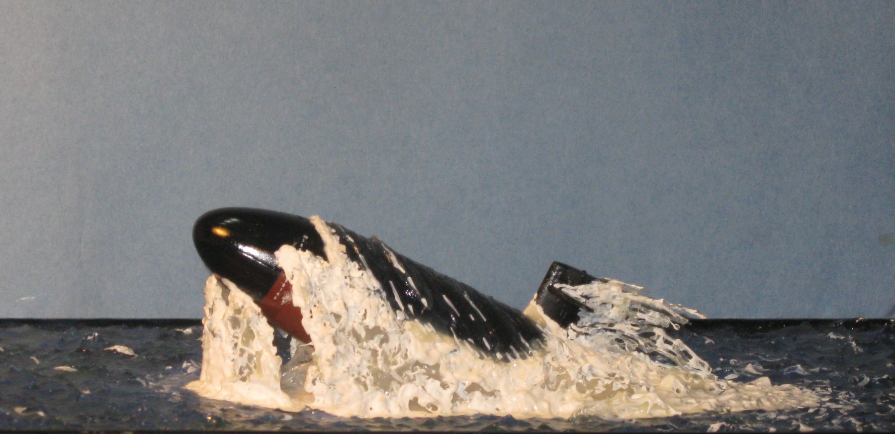
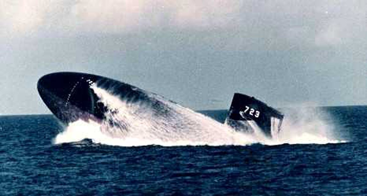
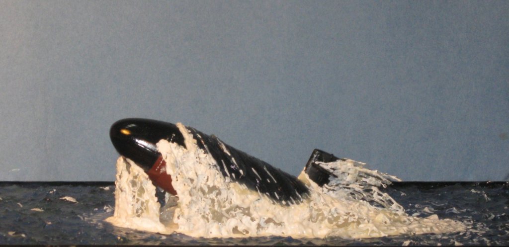
Hi sailor - This does not happen often, probably because it is so dangerous. It's called an 'emergency blow' or 'emergency surface'. They do train for it, though. A friend of mine used to call the exercise 'angles and dangles'. I'm sure you can imagine what they were referring to. As for leaping out of the water, I'm not sure if it was even possible before the newer classes of sub, but I was intrigued when I saw it in the movie. There are some cool YouTube videos out there too. Thanks for the compliment. I had fun doing it. Dan
- 287 replies
-
- 5
-
-
- michelangelo
- ocean liner
- (and 1 more)
-
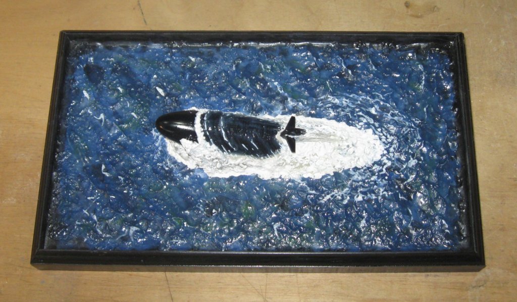
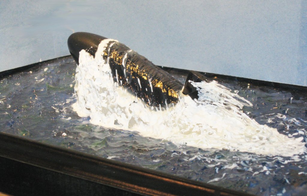
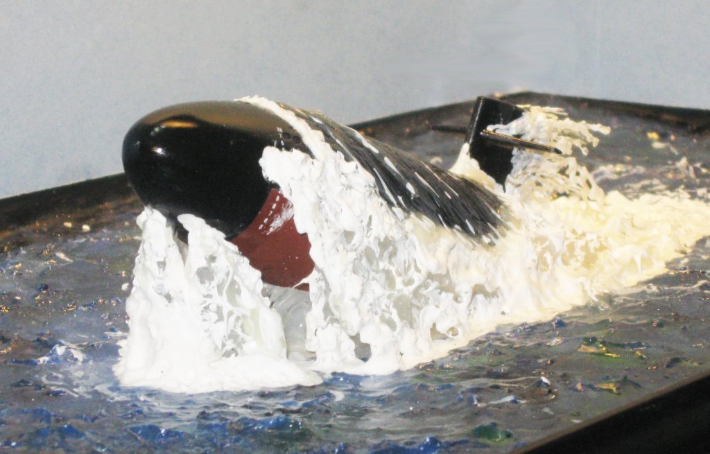
Hi all - Well, we can't all live on ocean liners alone. In some of the down time, I tried my hand at a little diversion. I recently watched "The Hunt for Red October" and was once again impressed with how far out of the water a submarine can get. A little internet research, a 1/350 model of USS Dallas, some experimentation with how to model water, and here we are. The base is 12" x 7", for a sense of scale. The caption, of course, is "FLY! big D!" Enjoy. Dan


- 287 replies
-
- 12
-
-
- michelangelo
- ocean liner
- (and 1 more)
-
Hi Kenny - Nice clean work on the backbone. Before you start adding frames, let me suggest that you do all of the shaping of these pieces that you can. It is so much easier to do this without the frames getting in the way. For example, the width of the keel tapers towards the stern, and the stern post tapers from top to bottom, making the extreme heel of the hull the second narrowest spot. (You may have done this already, but I could not tell in the photos.) The narrowest spot is the heel of the deadwood, which also tapers from fore to aft and top to bottom, and is thinner than the sternpost by twice the thickness of the planking. To get the planks to run smoothly against the sternpost the rabbet has to be wide and shallow. I do not know your plans, but there is often a dotted, curved line called the 'bearding line' which indicates the width of the rabbet. This width changes all along the length of the backbone and up the stem as the shape of the hull changes how the planks angle into the rabbet. The shallower the angle of attack, the wider the rabbet has to be. Let me also suggest that you cut the rabbet a little deeper than you think you need. It always surprises me when the planks want to ride higher than planned, and then they have to be planed or sanded to shape. Sometimes they ride so high that I have to go back and deepen the rabbet or I would have to sand right through the plank, all the while trying not to ruin parts and planks already installed. Better to make it deeper than needed, which can be filled with putty or even glue as the planking is installed. Best of success Dan
-
Kieth - Thanks for the link. I took a look and there might be something there if 3-D printing of the funnel cages does not work. I also looked at your Altair. Very impressive. I truly envy people who have such brilliant metalworking skills. Bravo. I will be following along from now on. Dan
- 287 replies
-
- 4
-
-
- michelangelo
- ocean liner
- (and 1 more)
-
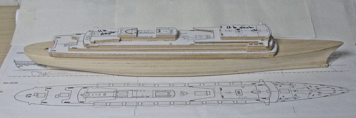
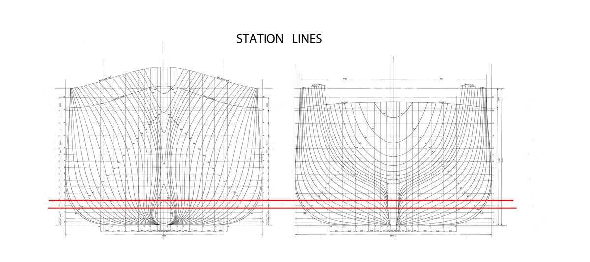
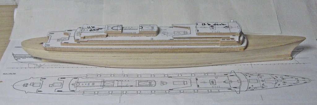
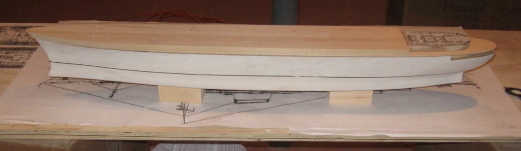
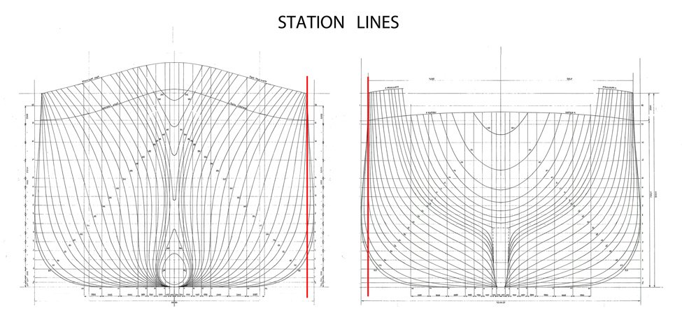
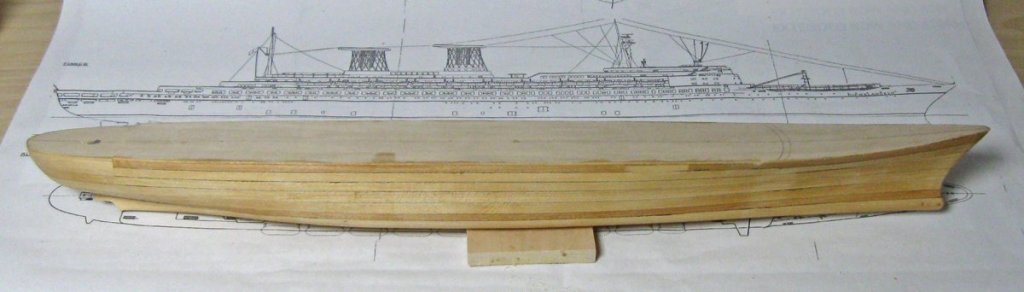
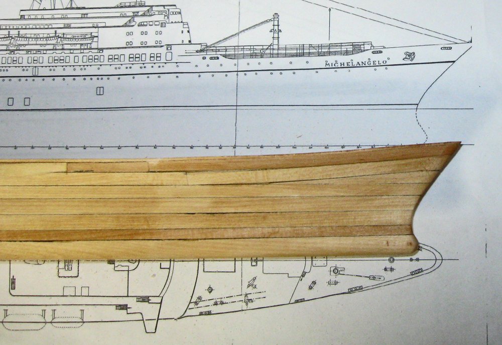
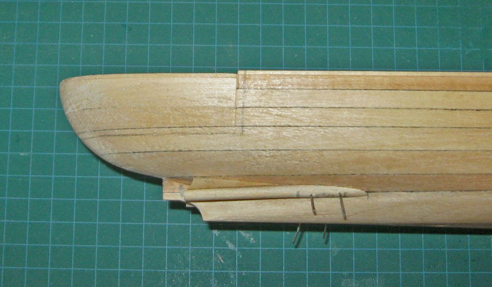
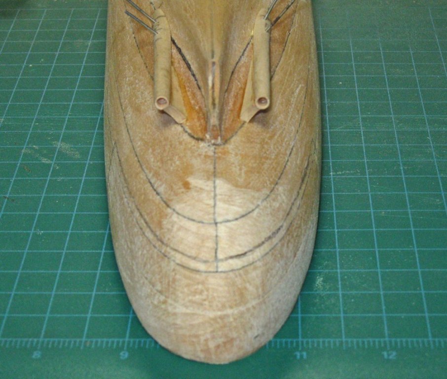
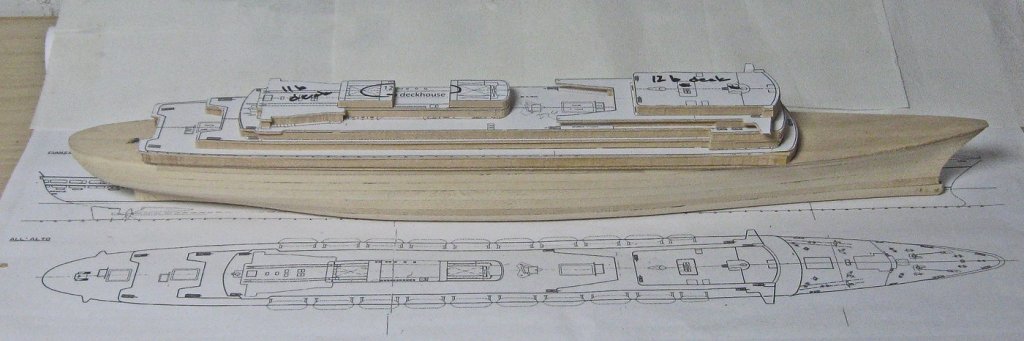
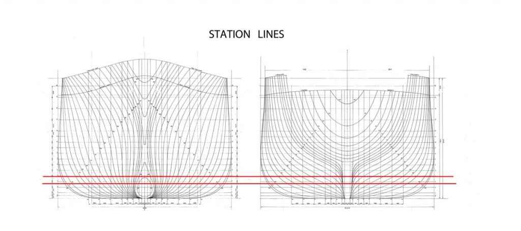
Hi all - When the last segment ended I was doing the initial shaping of the hull. Using the station lines plans I made some templates for the hull profile and worked the wood down to the proper shape. That lengthy and tedious task was made faster with power sanders, both belt and orbital. A light touch is needed, but after getting used to the weight of the tools they let me remove wood in a very controlled and delicate way. One thing I learned from the templates relates back to a discussion we had during the Doria build. There, I did not have the station lines plan until quite late, and even then they were from a commercial model kit, so I did not trust them. They seemed to show that the hull was narrower amidships just under the promenade deck than it was at the bilges. But after carefully examining a photograph of the Doria on the launching ways I did not see this at all. Others, who were more familiar with Italian liners, said that there was a tumblehome, just not much. It turns out that, for the Michelangelo at least, we are both correct, sort of. Here are the station lines, with a vertical guide line drawn from the top of the hull down on both the bow and stern views. Clearly, the lower hull is wider at its greatest breadth than at the sheer line. The difference is about 30 inches actual or 3/32” on the model. Not very large, but certainly some tumblehome. But when I lined up the station numbers I found that it only affected the center 20% of the length of the ship. Both ahead and astern of that area the hull either came straight down or started to curve the other way. In essence, what the hull has is not really tumblehome, but a pair of bulges amidships and just at the waterline. Saddlebags, really. Were these to get some more ballast lower down in the hold? Were they to artificially lengthen the waterline and increase speed? I have no idea. Nonetheless, this was noted and I tried to get the wood to take that shape in the carving process. Here is the hull taken down very close to final dimensions. At the bow you can see how the lifts had to be cut and pieced to achieve the line of the sheer. The third one down is that wedge that was mentioned in the last segment. At the stern the upper lifts have been cut short and pieced in. This block is secured with a screw and is removable. It holds the place of the deck houses and open decks that will be fitted later. I had an idea that I could drape form some plastic around this plug for the window units of these stern decks. Ultimately this did not work. I will discuss it and my solution in the next segment. The tapered propeller shafts and their webbing are being pinned in place. Having the black glue lines between the lifts was a particular help here near the rudder, where it showed me problems with symmetry as wood was removed. During breaks from sanding and shaping the hull I roughed out the superstructure. The plans were attached to basswood sheets with the photo spray adhesive as before and rough cut on the band saw. Deckhouses are cut from ¼” thick basswood, while the decks are 1/8”. The total from deck to deck is 3/8”, or just under 11 feet. Stacked on each other where they fit, there is a palpable feeling that a ship is starting to rise from the building board. Next I start the final finishing of the hull, and contrive a solution to the problem of the open decks and windows at the stern. Be well Dan

- 287 replies
-
- 19
-
-
- michelangelo
- ocean liner
- (and 1 more)
-
Hi Tom - Your Connie is coming together nicely. Really good work on the tops. And now, welcome to the wonderful world of rigging. This takes a completely different set of skills from the woodwork, etc. that goes into building a hull. This is more like learning to knit, or embroider. Best of success with the craft. I have been doing it for 30 or so years, and I am still learning and experimenting. For example, I have found that when I have a deadeye that is a little too high or low, I unlace the lanyard and spin it around before relacing. In one direction the shroud will unwind and lengthen, in the other, it will tighten and shorten. If you do that with two or so of the most out of line ones the deadeyes on your foremast will straighten right out. Don't worry that the upper deadeyes may end up at an angle, the sheer pole that you will be setting up later will take care of that. Hope that helps. Dan
- 1,350 replies
-
- 5
-
-
- constitution
- model shipways
- (and 1 more)
-
Hi Kenny - Mark is right about plans going out of true if you use a water based glue. After making that mistake, I now use a spray mounting adhesive used for photographs. 3M has a good one. It allows some repositioning when attaching the paper to the wood, and removes easily after the cutting is done. Hope that helps. Dan
-
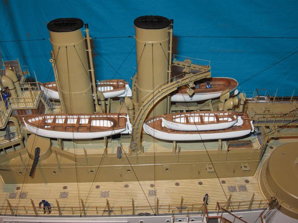
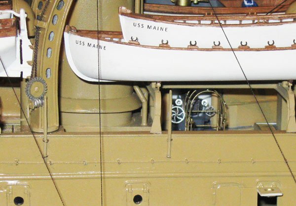
Got it. Now it makes sense. For the boats, have you considered doing vacuum formed hulls? That is how the boats were done on the USS Maine in the Brooklyn Navy Yard museum. The learning curve is about the same as for RTV casting, and there are small units available commercially so you don't have to reinvent the wheel. Dan
- 2,625 replies
-
- 12
-
-
- kaiser wilhelm der grosse
- passenger steamer
- (and 1 more)
-
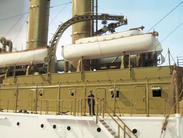
Nils - You are getting very good with those railings. Nice work. I understand adding "U" channel top and bottom, but what is happening in the 3rd photo, the one on the scorched building board? Dan
- 2,625 replies
-
- 5
-
-
- kaiser wilhelm der grosse
- passenger steamer
- (and 1 more)
-
Nils - really nice work. I never noticed the bolts holding on the blades of the propellers. Exquisite. Dan
- 2,625 replies
-
- 5
-
-
- kaiser wilhelm der grosse
- passenger steamer
- (and 1 more)
-
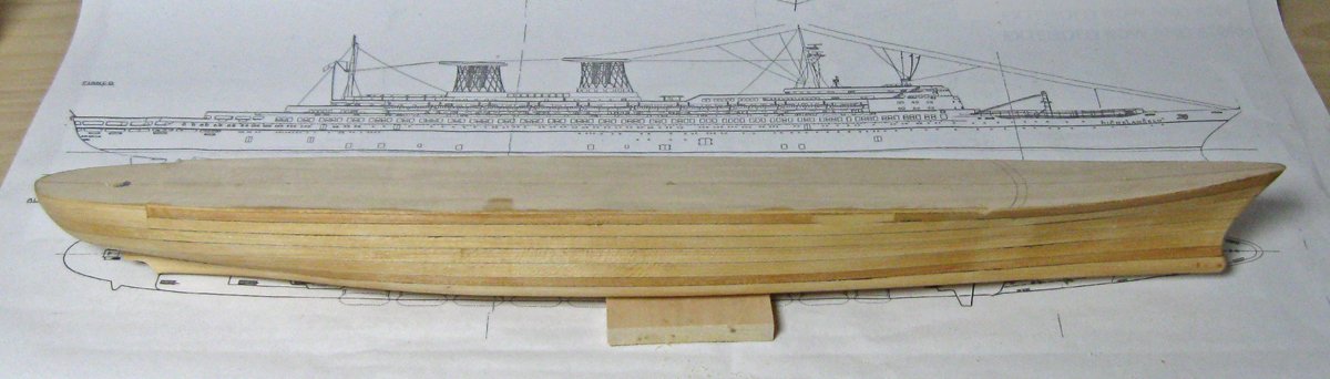
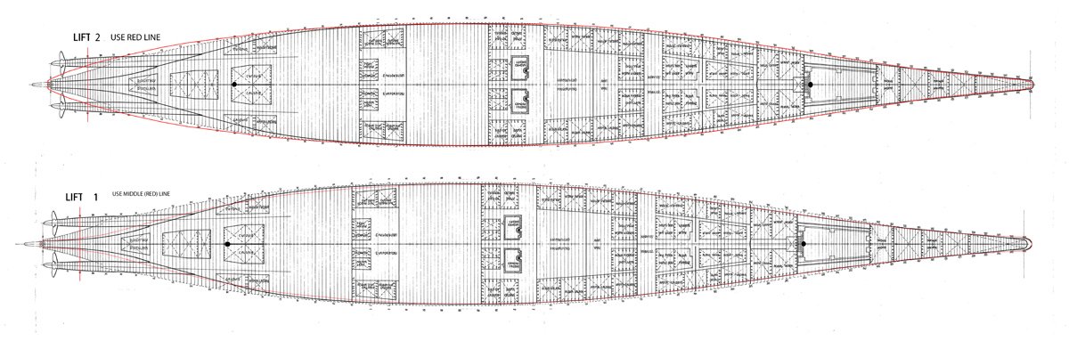
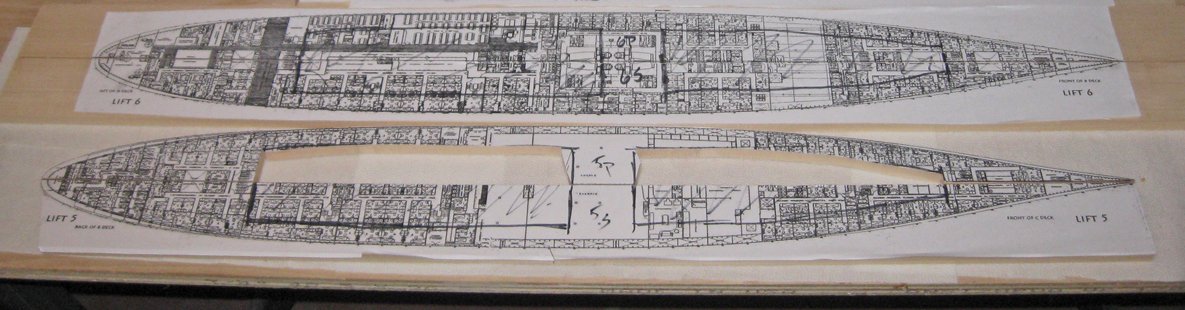
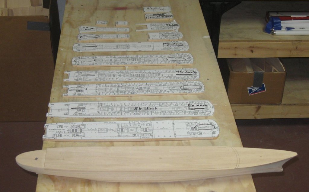
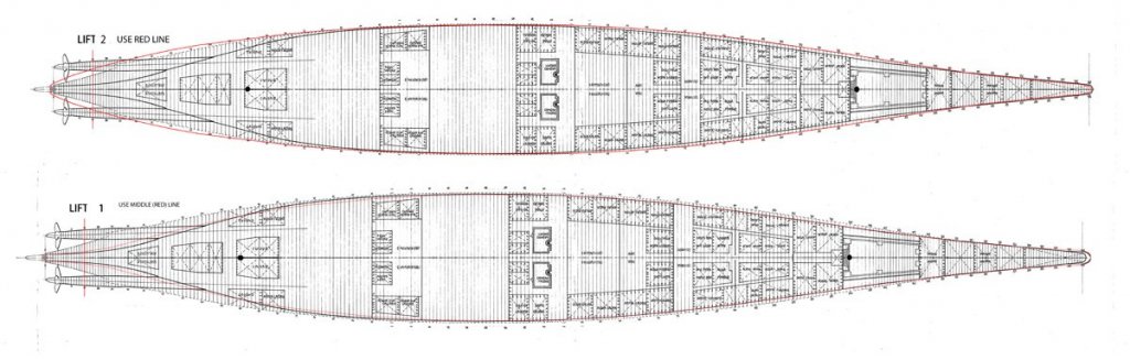
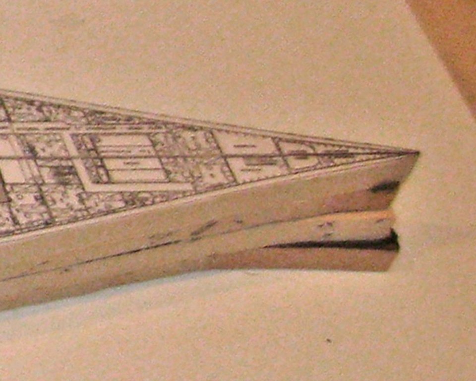
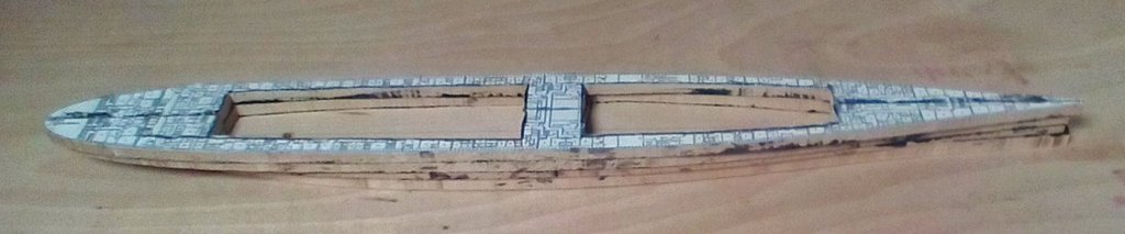
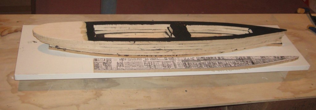
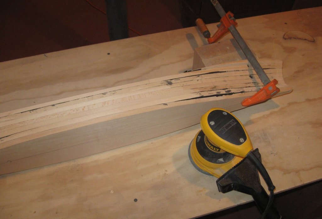
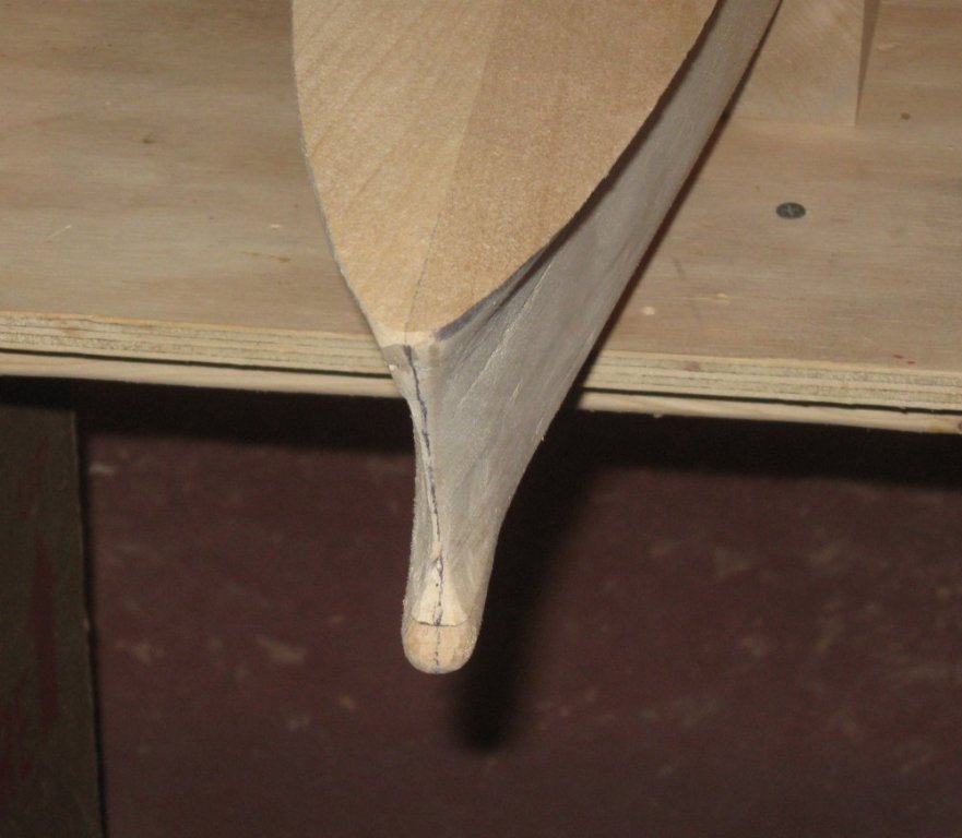
Build Log 3 – Shaping the hull Hi all – Thanks for the likes and comments, devilishly clever as some of them are. . . And thanks to Druxey, Michael, and especially Bob for helping me with the funnel cages. It looks like I will be working with Bob to have them printed in 3-D. I’ll report back on the progress and results. Leaving aside the issues with the funnel cages, the next step was to shape the hull. The first problem was that the plans did not have the specifics of the lower deck spaces, just a drawing labeled “steva” or bilge. It covered much more than the lowest two lifts, so the outline of the hull shape for these lifts was impossible to determine. I had to go back to my high school class in engineering drawing to plot them. I took the station lines plan and drew the horizontal lines for the locations of the tops of the first two lifts. Plotting the distances from the centerline for each station gave me the offsets, which were laid out on the bilge plan and joined by smooth curves. Here they are shown in red for the lower two lifts. The paper lifts were cut out and laid down on basswood planks along a drawn centerline. They were affixed with spray adhesive for photo mounts, which can be repositioned as needed and then removes easily. The lifts were cut along the plotted lines with the band saw. In the lifts plans you can see two black dots along the waterline. These located holes for the captured “T”-nuts which will be used for the future mounting hardware. The nut goes into the hole in the lower lift and its flange is then trapped by the upper lift. The hole in the upper lift allows free movement of the mounting bolt to any depth. At the bow some extra material was left on these lifts to build up the bulb that increases efficiency at high speeds. Here are the first 4 lifts laid up but before shaping. Above the second lift I made the hollows in the hull. This was first of all to lighten it a bit, but primarily to give any stresses from wood movement somewhere to go rather than deforming the exterior of the hull. Here are several lifts in the process. I first select basswood planks that are half the width of the overall model. Two of them are clamped side by side and the paper plan glued to them along that line. A sharp knife is run along the seam and the port and starboard sides are separated. The lift is sawn along the exterior line, and two large spaces are cut from the middle. A bar of wood is left amidships for strength. Sharp eyes will notice that these are not the lifts for the Michelangelo, but reprised from the Doria. I did not think that I was going to post this portion of the build, since the techniques are the same as on the Doria. But I decided that to tell a complete story I had to show how the hull was built up. Unfortunately, I had missed the chance to document the process, so I am using the old illustrations. As with the Doria, I used black glue to join the lifts. This is nothing more than a few drops of black acrylic paint mixed into the glue. It starts out messy, but gives an indelible line between the lifts and, because of the split lifts, along the centerline at the bow and stern. Here are the first 4 lifts of the Michelangelo glued up. You can must make out the location of the mounting hole in the aft hollow chamber. Later in the process the hull block is almost complete. The next lift to be added is cut short at the stern to make the space for the open working deck and fantail deck. It is also solid, to make a continuous surface that can be sanded to the curve of the sheer. Once the block was fully laid up the shaping process started. Using powered sanders and grinders the hull was brought to approximate shape. Where there were concave areas, such as under the stern fairing into the rudder post, or under the flare of the bow, various hand held curved rasps and sanders were used. Here you can see the benefit of the split lift and black glue. No matter how much material I removed, the lines always remained. Next time I will cover the final shaping of the hull block and the beginning of planning for the upper decks. As always, be well Dan

- 287 replies
-
- 17
-
-
- michelangelo
- ocean liner
- (and 1 more)
-
I have always said that I am a medium-tech sort of guy. I tend to cobble something together that does the job, like my ropemaker. But I am fascinated by all the things that the new technologies promise. I have seen some really excellent examples of 3-D printing at various meetings and conferences, and the products are getting better all the time. That said, I have yet to see the actual production process master a smooth curved surface without a lot of effort = time = money. But I am prepared to be convinced that it can handle these cages with their diagonal edges. I can always fall back on the lo-tech methods if needs be. Bob - would be very grateful for your help in working up the learning curve. I have all the plans at high resolution, and several other close-up photos to answer questions of detail. Let's talk. Druxey - am I really that old? When did photoetching become "lo-tech" ! ! Dan
- 287 replies
-
- 6
-
-
- michelangelo
- ocean liner
- (and 1 more)