shipmodel
-
Posts
941 -
Joined
-
Last visited
Content Type
Profiles
Forums
Gallery
Events
Everything posted by shipmodel
-
 Hi Pat - No, the lifeboats are all much further forward. But if there were inflatable or broken down life rafts on the Promenade deck, I guess these doorways could be used for emergencies. I am not enough of an ocean liner expert to know this detail. Dan
- 287 replies
-
- 3
-

-
- michelangelo
- ocean liner
- (and 1 more)
-
Hi Marc - All very good questions, to which I don't have a lot of answers. Here is what I think I know - There are, in fact, doors in the bulwark rail. There are two outlines drawn under the openings on the plans profile that fit the locations of the door symbols, and would make sense as access points for crew and light cargo, or emergency exits. None of my photographs are of sufficient resolution to be sure, but I can't think of another way to justify the plans to each other. Yes, they should be symmetrical. My speculation is that the reason is either 1) the doors swing both ways, like a restaurant kitchen, so they are drawn correctly, or 2) they are not drawn correctly. But since they are interior doors i didn't worry about it. Certainly a possibility. I couldn't make any feature fit both the dots and the dashes at the same time. Fortunately, as you say, they are mostly interior and covered. Yes there is a sister ship, the SS Raffaello, which is almost the same, but not quite. Most of the differences are cosmetic, so am using photos of her for structural details where I don't have a sufficiently detailed photo from Michelangelo. None of the photos of her show this area in any detail. Dan

- 287 replies
-
- 4
-
-
- michelangelo
- ocean liner
- (and 1 more)
-
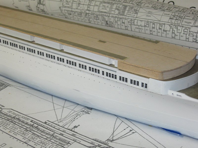
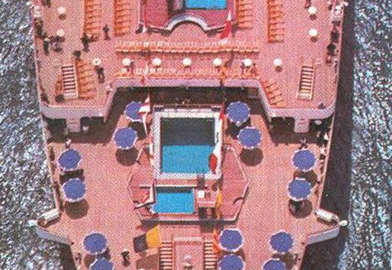
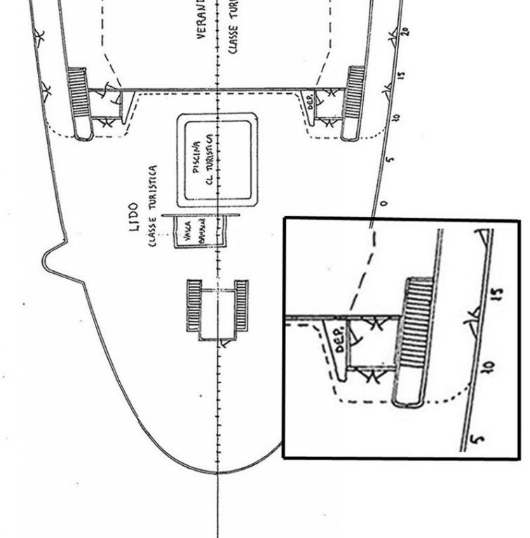
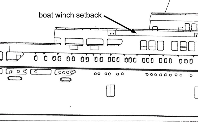
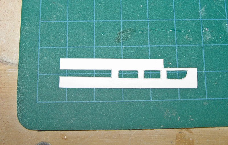
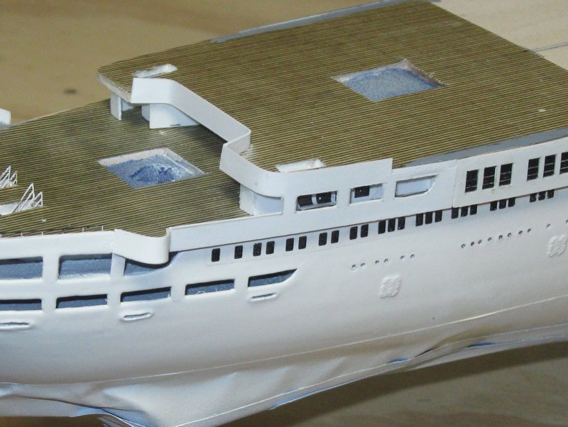
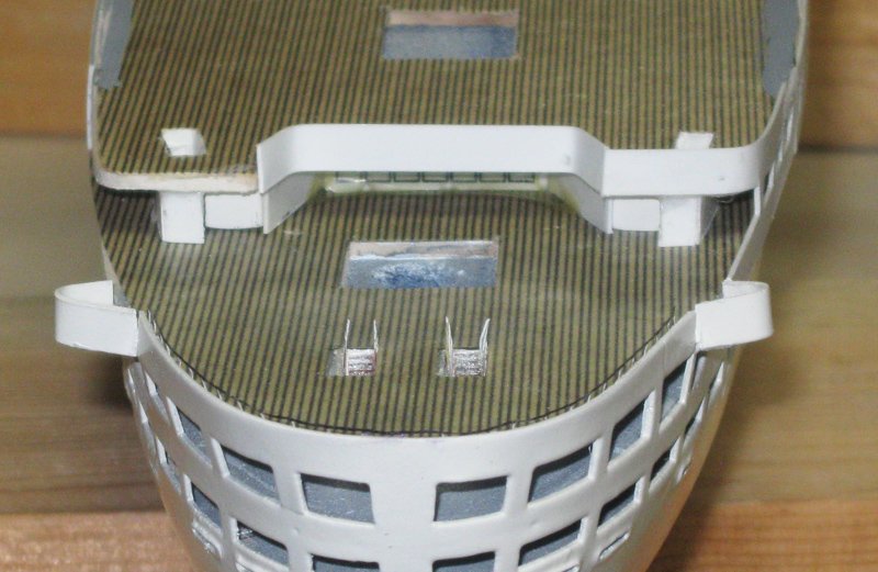
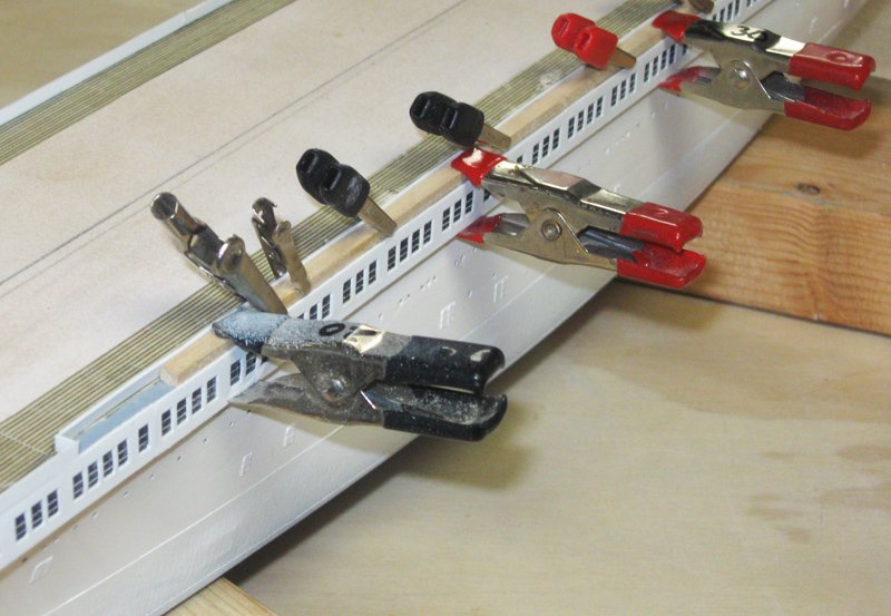
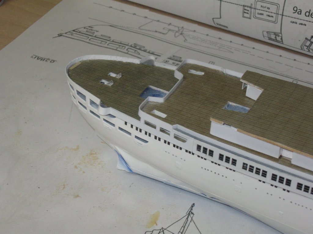
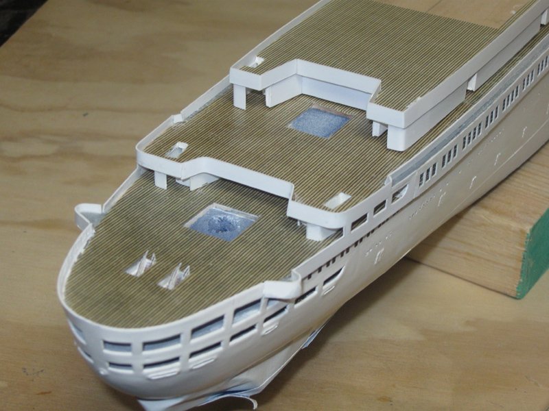
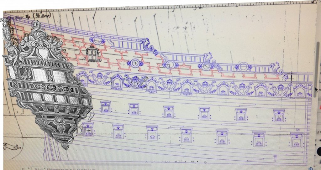
Hi all, and many thanks for the comments and likes. This model is turning into an exploration of a number of different solutions to problems which do not come up in a sailing ship model. I hope my experiments can shorten the learning curve for others, the way that all my reading has shortened mine. Druxey – although I cannot claim any direct relationship with the family shown, I have to confess that during my college years I often bore an embarrassing resemblance to the young man on the right. Thank god that phase of my life is over. LOL I hope all my American friends had a good 4th of July, and everyone else just had a great weekend. The Admiral got away from work for a week and we spent it with the family upstate. I managed to sneak away to the workshop, and made some good progress. I will post several segments in the near future. Here is the first: I was installing the window segments on the promenade deck when I left off. Here is how they came out after gluing. Above them you can see the Boat deck cabins after initial shaping and sheathing, with one of the inset doorways. On top is the rough unsheathed layer for the Upper deck. The seams between the segments were filled and overpainted with gloss white. The upper and lower edges were sanded so they fair into each other. At the forward end they butt and fair into the sheathing of the forward face of the Promenade deck. This is pretty simple. But at the stern the Promenade deck ends with three and a half openings that fair at the lower edge into the bulwark rails leading around the fantail. Their upper pieces form the bulwark rails of the Upper deck that surround the pool area. From overhead and aft you can see that this upper deck creates a large overhang that cradles the lower pool with access by a pair of angled staircases. The outer corners of the deck and bulwark rails are rounded and are the continuations of those bulwarks above the windows. An expanded section of the plans shows the structure of this area. Unfortunately, some details are still unclear. For example, in the enlarged insert you can see how the stairway comes down to what looks, for all the world, like an enclosed area. There are no doors indicated, as there are everywhere else. How is the staircase accessed from the lower deck? Also, is there a difference indicated by the dotted line versus the dashed line which both seem to indicate the shape of the upper deck? What is the small triangular area labeled “dep.” with a door into it? The side view in the plans does not help. There is not much detail, and it raises more questions than it answers. For instance, the area above the Promenade deck windows is drawn in to indicate a break in the line of the bulwark rail. Without going into all the photos that were examined, it turns out that this is a narrow setback that houses the boat winches. But there are no plans that show this feature from the top, so its depth could not be taken off as drawn. More on this later. In any event, paper patterns were made up based on my best guesses as to the answers to these and other questions, then tested before being used to lay out the styrene piece. This piece was set in place and the upper extension was wrapped around the Upper deck layer. This creates a semi-enclosed passageway leading to an entry door to the Promenade deck. I opted to semi-enclose the stairs with an L-shaped wall that is open to the inside of the deck area, as can be seen in the port side wing. A few windows were laid out along the inner wall of the passageway as seen in some of the photos. They were done by making up custom water-slide decals on my computer and printing out onto decal film. The line of windows that can be seen below the Promenade deck were done in this fashion as well. And here is the view from aft with the starboard and center bulwark rail pieces installed. The port side piece was shaped and installed, then all of the joints and seams were sanded fair and even. Looking closely you can see that the fantail curve has a dark handrail above the bulwark. It was my first attempt at this feature and turned out not to be acceptable. It has since been removed and future segments of the log will go into the various solutions that were tried. As of this writing I am still not satisfied with the results. Next I turned to the boat winch setback. It had to be made up of an unsupported bulwark railing that was perfectly straight and attached only at the bottom. I estimated that it would be about 4 feet wide to give enough room for the machinery. I cut a strip of wood just over 1/8” wide and clamped it to the top of the Promenade deck. A strip of styrene 3mm high was cut and clipped to the wood strip. The styrene was spot glued with cyano from the inside. When it could support itself the clips were removed and a bead of white glue was painted along the base. The railing came out just as I hoped. Here is how she looked. Unfortunately, the depth was wrong. With a 4 foot setback, when I placed the Boat deck on top, there was not enough room for the passengers to walk past each other between the railing and the deck house. After agonizing for a bit, I gritted my teeth and removed the railing as carefully as possible. It wasn’t carefully enough, and some sections of the decking came up with it. But after sanding away any glue residue, the decking sections were replaced and the bulwark rails relocated to form a 1/16” (2 foot) setback. Now when the Boat deck house is set in place, the walkway is much better sized for passenger use. As you can see, the Boat deck house is being sheathed and its deck and bulwark railings are being set up. This is where I will pick it up in the next posting. As always, comments and alternate solutions are very welcome. Be well Dan
- 287 replies
-
- 11
-
-
- michelangelo
- ocean liner
- (and 1 more)
-
Hi Nils - Just back from a week away and catching up. Nice work on the case, and some new construction ideas. Thanks. Be well Dan
- 2,625 replies
-
- 4
-
-
- kaiser wilhelm der grosse
- passenger steamer
- (and 1 more)
-
Hi Marc - Not sure how the windows would come out in 3-D printing. Probably pretty well. But the laser was the first thing I thought of. Not much more to it than that. Dan
- 287 replies
-
- 3
-
-
- michelangelo
- ocean liner
- (and 1 more)
-
Thanks, Keith - Even where the laser did not completely cut, the channels that it made were invaluable in guiding my knife blade. After that it was just a matter of magnification. The first thing I do when starting to work is to put on my optivisor. The last thing I do is take it off. Dan
- 287 replies
-
- 4
-
-
- michelangelo
- ocean liner
- (and 1 more)
-
Hi Nils - Thanks so much for the compliment. I think it is coming along nicely too. You seem to have duplicated my entire post before putting in your reply. Could you edit the post by taking it out and just leaving your comment? I don't want the log to end up too long. Thanks Dan
- 287 replies
-
- 4
-
-
- michelangelo
- ocean liner
- (and 1 more)
-
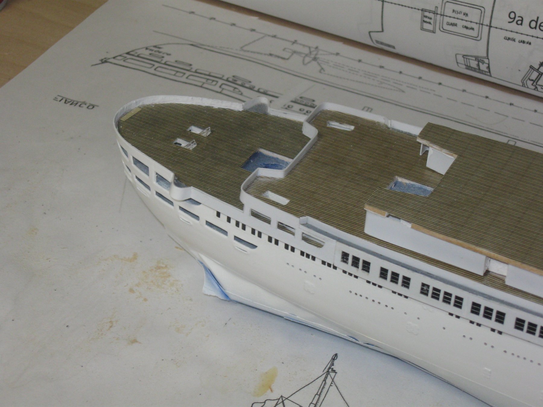
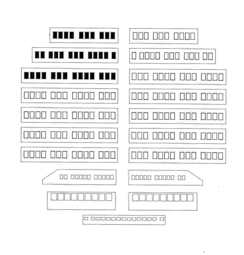
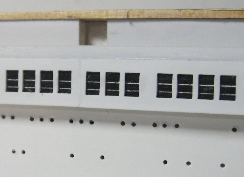
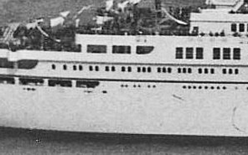
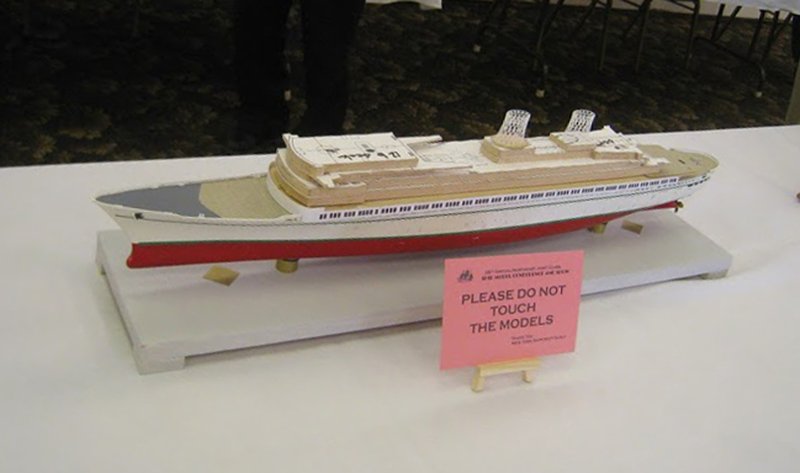
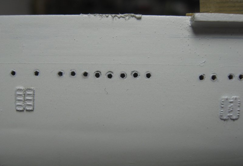
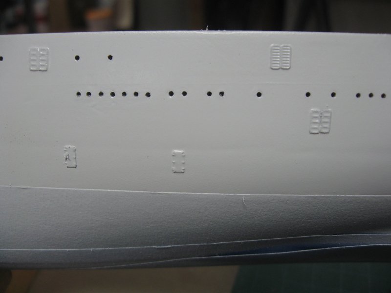
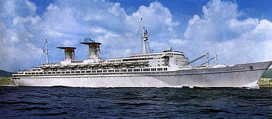
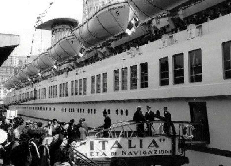
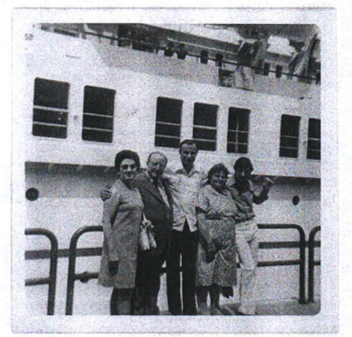
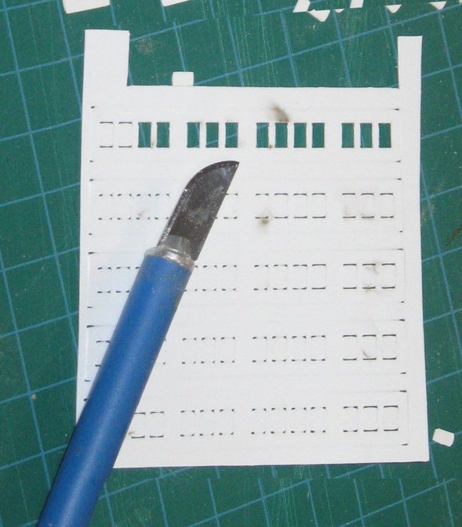
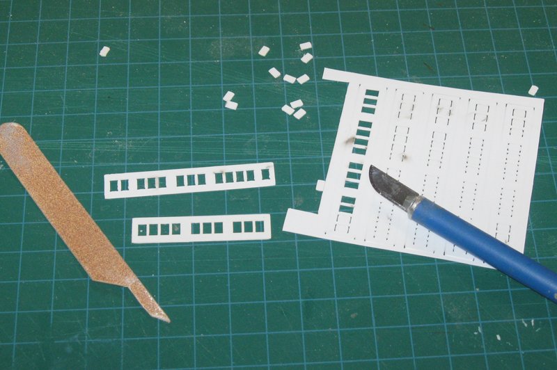
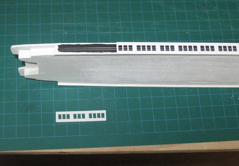
Hello again to all – I hope everyone had a good Father’s Day, whether you are a father or not. Between teaching swimming to grandkids and cooking on the grill I found a little time to work on the Michelangelo. Here is a short post. At last posting the portholes were being finalized and some extra details were temporarily added to make a better impression at the Northeast Joint Clubs Show. After the show the green stripes were removed, as were the anchors and railings. The lower hull was masked at the waterline and I got to work on the portholes. Here is how one section looked at the time. You can see that when they were adjusted up or down as needed to get a straight line they left small depressions around the brass beads. You can even see, looking critically, that the bead openings are rounded pentagons and not perfectly circular. Neither defect was very obvious, except in close-up photos, but I wanted to correct them if possible. I first took some white primer and decanted it from the rattle can, leaving it to thicken for a few minutes. With a small brush I filled each depression, mounding the paint up to allow for shrinkage as it dried. When it was fully hard the portholes were sanded flush with fine grit paper wrapped around a hardwood block. After sanding, the upper hull was spray painted with two coats of gloss white. This gave me a beautifully smooth finish, which I wanted, but the paint filled some of the openings in the beads, and left others visibly lopsided. Taking a 0.045” drill mounted in a pin vice, each porthole was opened by hand to a scale dimension of 16”. All 846 of them! Now they were round rather than pentagonal and matched the rimless look of the portholes in my photographs of the ship. Sometimes the correction of a problem leads to a better result than if the problem had never arisen. The next problem to tackle was the windows along the length of the promenade deck. They are a very eye-catching feature of the ship, and I wanted to try to do them justice. Detailed photos show that the windows are inset into deep frames, with two visible horizontal lines appearing in the lower half of the openings. These are probably protective bars behind the glass, but it is difficult to tell. Sometimes I get distracted by the attractiveness of the family in the lower photo. Working from the overall photograph I divided the promenade into seven sections of windows. The five center ones were made up of identical repeating sets of 3-4-3-4 windows, while the forward and end ones had irregular patterns. The seven had to total exactly 804mm long to fit the space on the model. At Joint Clubs I had fashioned some paper place-holders for them. This was not only to make a better impression, but as a trial run for my layout of the frames. On paper this was not too difficult. Using CorelDraw I laid them out over a cropped section of the plans. The program made it easy to adjust and replicate a prototype window, and to form the copies into sets and the sets into sections, then mirror them to create the windows for the other side of the ship. A few tweaks and reprints, and the paper sections laid out exactly. I also took the opportunity to lay out some window sections for the upper decks and bridge. Now to make them out of a more durable substance. To match the rest of the model they were made from white styrene sheet 0.020” thick. In the past this would have meant cutting out each opening individually, but I was fortunate that fellow NY Shipcraft Guild member, Charlie Zobel, had access to a laser cutter that accepted the CorelDraw file. Unfortunately, the laser did not cut equally in all areas of the sheet. Sometimes it did not go through, and sometimes it did. Increasing the laser power a bit might have finished all the cuts, but there were several scorch marks and at some corners the plastic looked a little melted, so increasing the power was not tried. I finished the cuts with a #10 blade and popped out the unwanted windows. This left me with somewhat rough edges along all sides of the openings, but a bit of sanding with a shaped emery board smoothed them out. Since there are 186 windows, this did take a few hours of tedious work, so I would have to say that this first attempt at laser cutting styrene was not a complete success. Nonetheless, I was happy with the finished sections, and when tested on the model, they fit within 1mm of the perfect length. To install them, the side of the promenade deck was painted gloss white, then overpainted with flat black. When the paint was dry a compass with a steel tip was used to scribe the two lines through the black to expose the white. The deck piece was set up on its side and the styrene segments were laid over this base from bow to stern using a slow-setting epoxy. The long open time allowed me to adjust each segment to the deck and to each other. Here the final section is about to be installed on the starboard side. When I was satisfied with the placement of the sections they were left alone for the epoxy to harden overnight before the process was repeated on the port side windows. Many additional details have to be added to the promenade deck before it can be secured to the hull, but by then it was time for me to get the burgers on the grill, so that was as far as I got. More soon Dan

- 287 replies
-
- 14
-
-
- michelangelo
- ocean liner
- (and 1 more)
-
And to add another quirk - the SR seems to have banners or ribbons running under the stern chase ports below the counter. Marc, you suggested this for the location of the motto, and I said that I never saw any evidence of such a decoration. Now here it is. Go figure Dan
- 2,699 replies
-
- 4
-
-
- heller
- soleil royal
- (and 9 more)
-
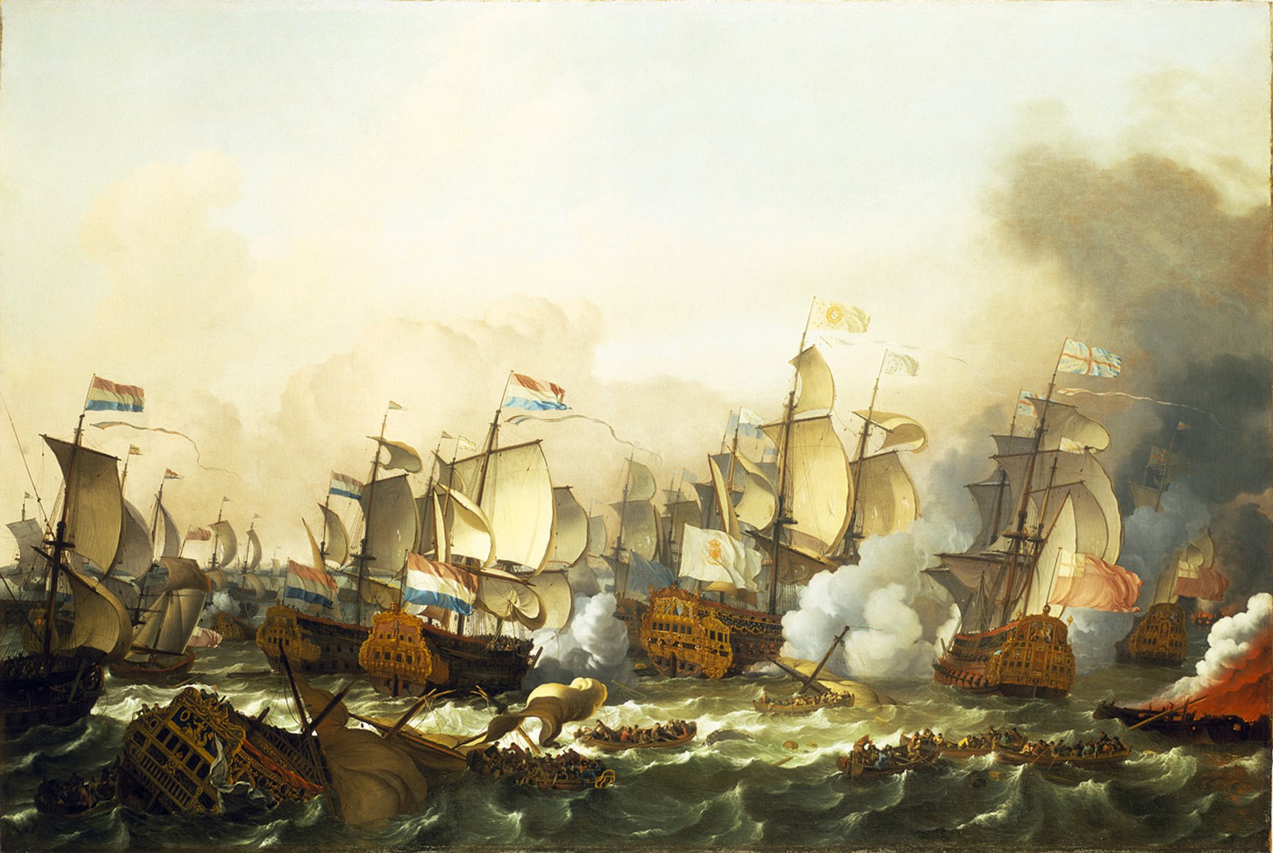
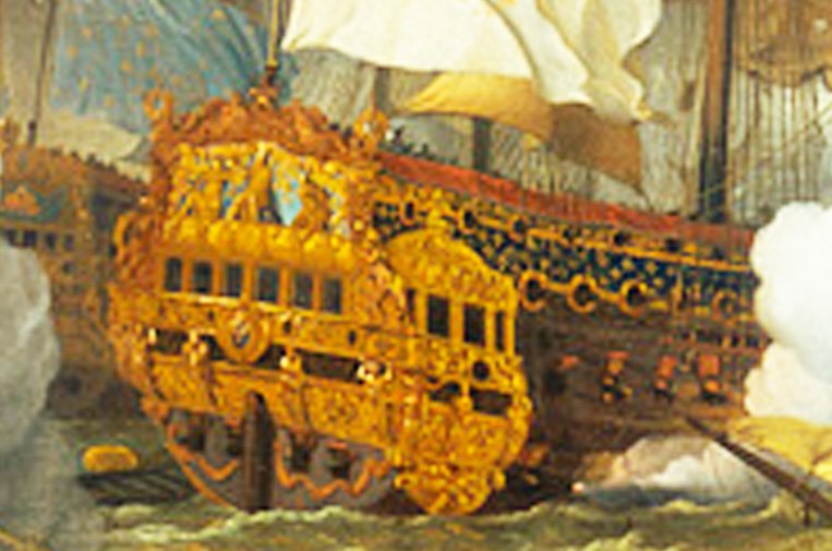
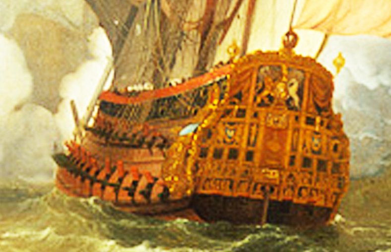
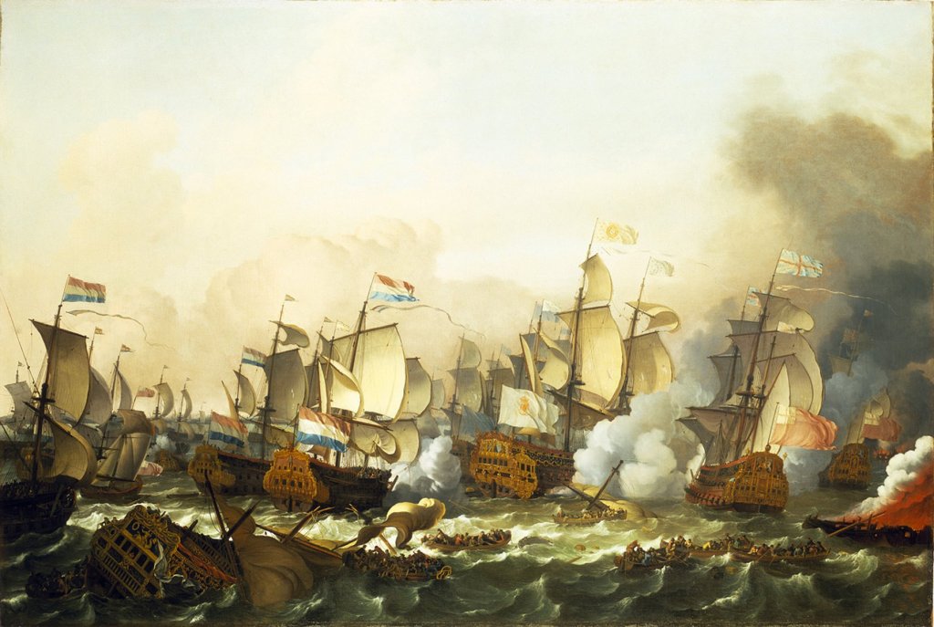
Hi all - In some spare time I have been trolling the net to see what other images of SR and other contemporary ships exist that might add to the discussion of the true shape of the ship, especially at the stern. Here is one that I found of the Battle of Barfleur (May 29, 1692) painted by Ludolph Backhuysen. He is known as the primary Dutch marine painter after the Van de Velde family left for England. And here is a close-up of the central ship, which is confidently identified as the SR. Note that the sheer at the stern is quite flat. Perhaps this is due to the perspective of the artist being much further away than Berain's image. It may be some unfamiliarity with the ship, but note that the Dutch ship to the left of the SR has a much steeper sheer, while the British ship to the right also has a flat sheer, which we know is correct. Just my way of adding to the confusion. Dan
- 2,699 replies
-
- 5
-
-
- heller
- soleil royal
- (and 9 more)
-
Hi Ken - You are really making good progress on the rigging. Soon she will be an eye-catching addition to your home. Could you tell me, in the first photo, what are the heavy black lines that seem to run from the topmast cap to the t'gallant yard? Thanks and congratulations, again. Dan
- 481 replies
-
- 2
-
-
- rattlesnake
- model shipways
- (and 1 more)
-
Frank - Welcome to the MSW family. No need to feel in any way intimidated by this collection of in-laws and outlaws. Your beautiful work speaks for you. What machines and techniques do you use to get such precise aluminum fittings? Congratulations on the successful models and thanks for sharing them with us. Be well Dan
-
Nils - Yes, attach those shelves VERY strongly to the wall studs. I once had to restore about 6 ocean liner models for a collector whose entire wall of shelves came crashing down one night. Not a pretty sight. Dan
- 2,625 replies
-
- 5
-
-
- kaiser wilhelm der grosse
- passenger steamer
- (and 1 more)
-
Hi Vossiewulf - Thanks for suggesting the 'perspective' adjustment function in Photoshop. I fooled around with it a bit and it really does do a good job of adjusting for the optical distortions of perspective and parallax. Dan
- 2,699 replies
-
- 2
-
-
- heller
- soleil royal
- (and 9 more)
-
Really nice, Nils - It is taking on the unmistakable compelling appearance of the ship. All of those little details add up to much more than the sum of the parts. Excellent work. Thanks, as always, for letting us accompany you on your journey. Dan
- 2,625 replies
-
- 7
-
-
- kaiser wilhelm der grosse
- passenger steamer
- (and 1 more)
-
Hi Dick - Glad you have it licked. Looking forward to seeing the results. I was just agreeing with Druxey that acrylic matte medium is a good stiffener and has worked for me. Dan
-
Hi Woodrat - I have had good success, like Druxey, with acrylic matte medium. I lay up the sail with all its details - bolt ropes, cringles, reinforcements, etc. Then I lace it to the spar and suspend it horizontally from the corners of the spar and the lower corners of the sail. The matte medium is painted on and allowed to dry completely. The simple weight of the liquid medium pulls the sail into a nice billow. This can be encouraged with a small bag of rice. Once dry, it hangs quite nicely, I think. You can read more about the method, and some mistakes, in my build log of the Queen Anne's Revenge. Best of success. Dan
- 632 replies
-
- 12
-
-
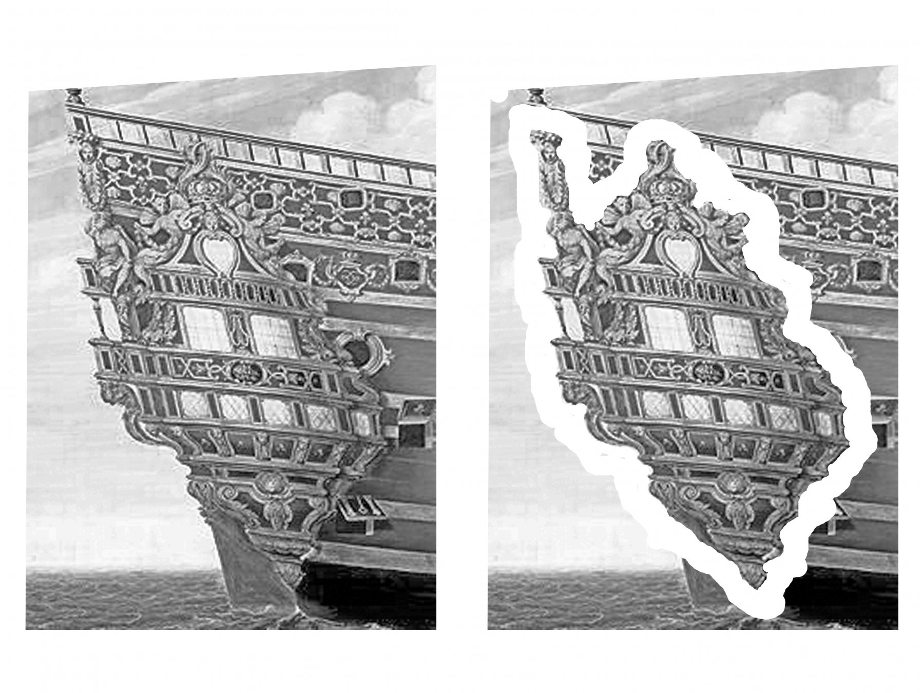
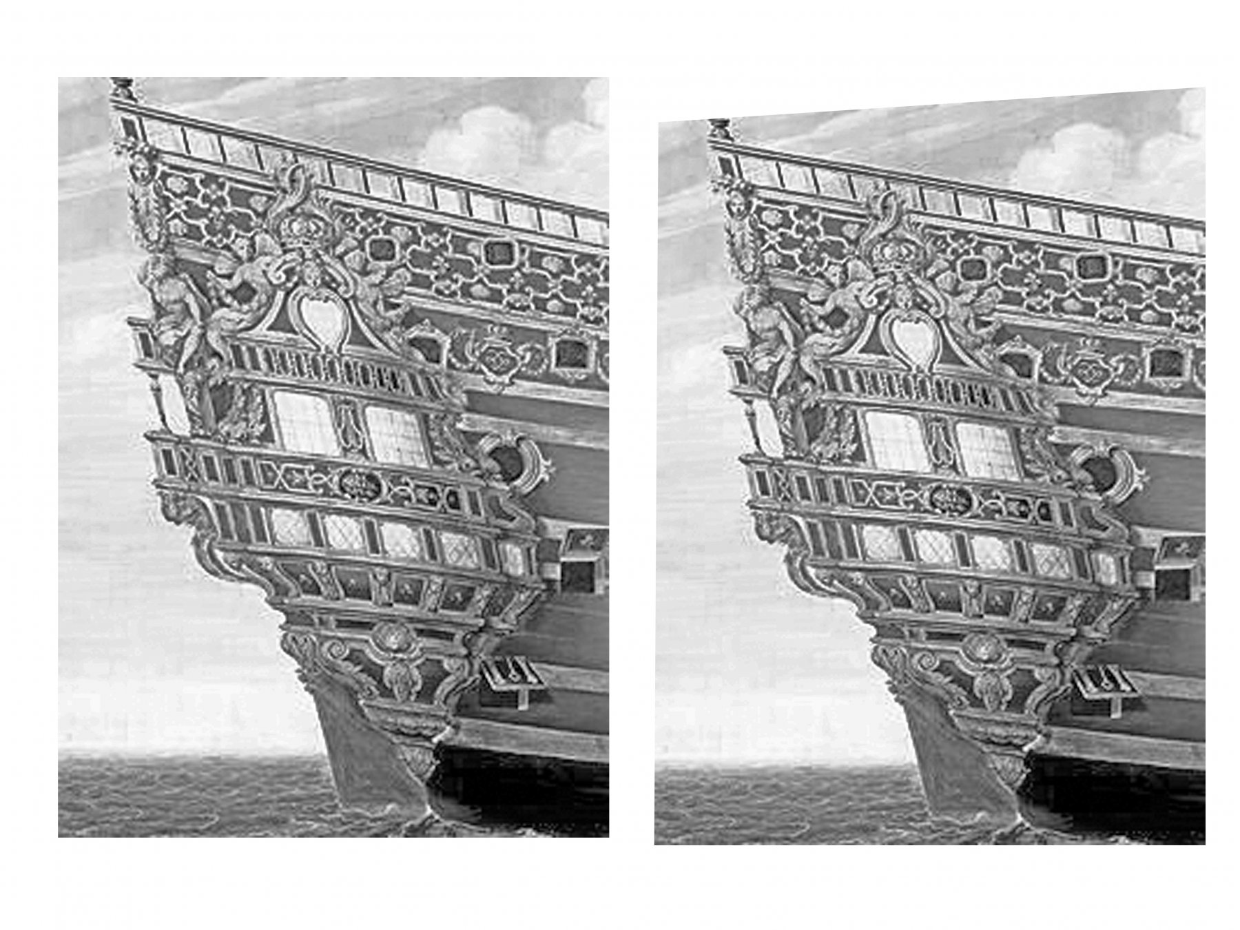
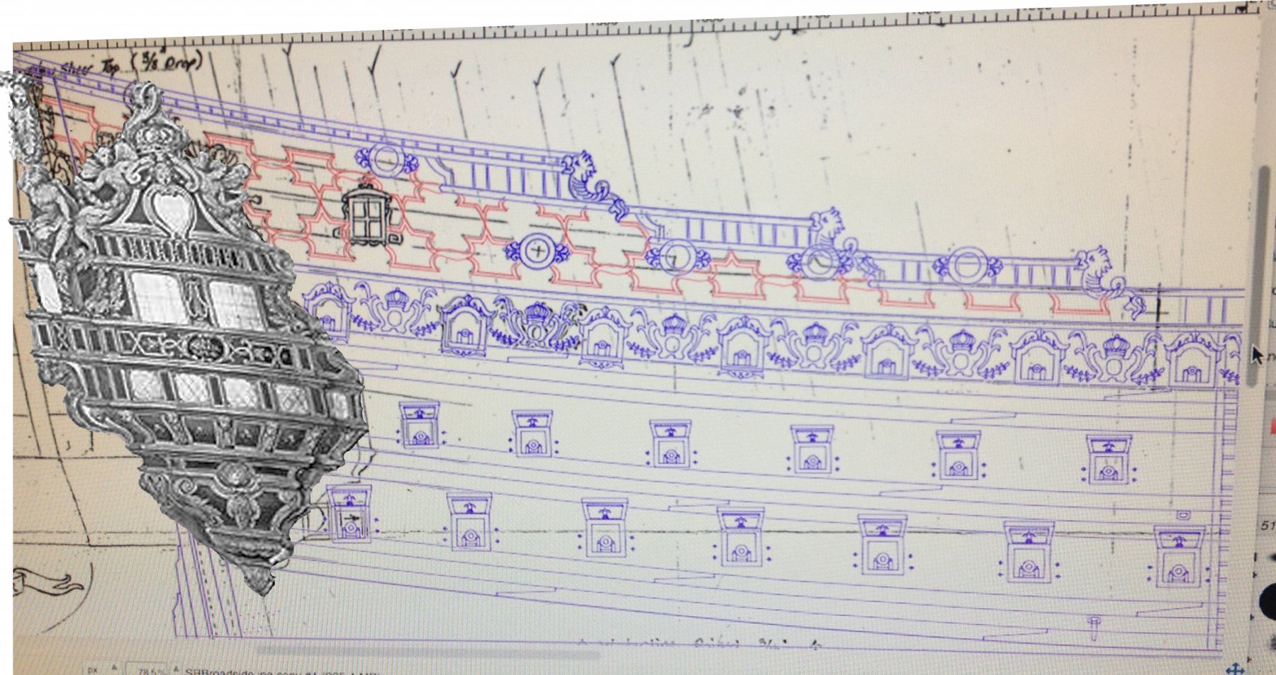
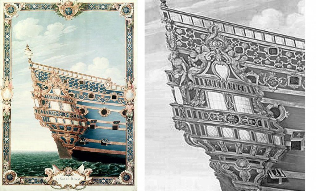
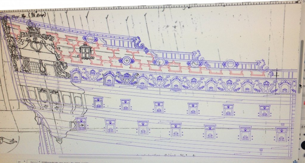
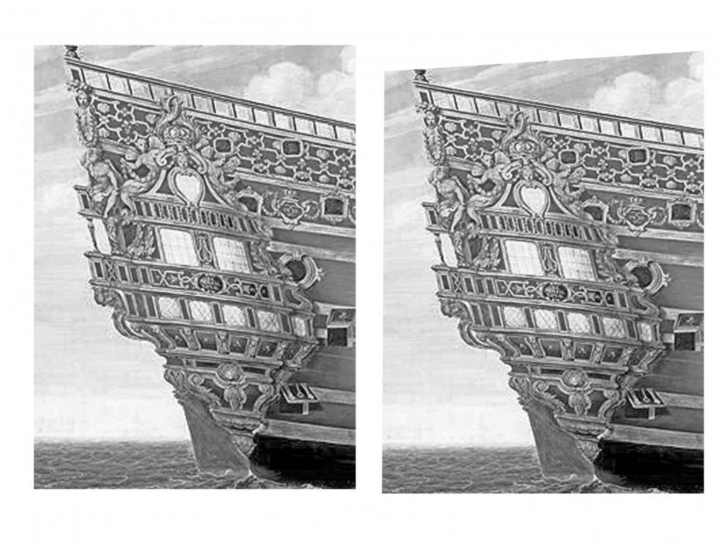
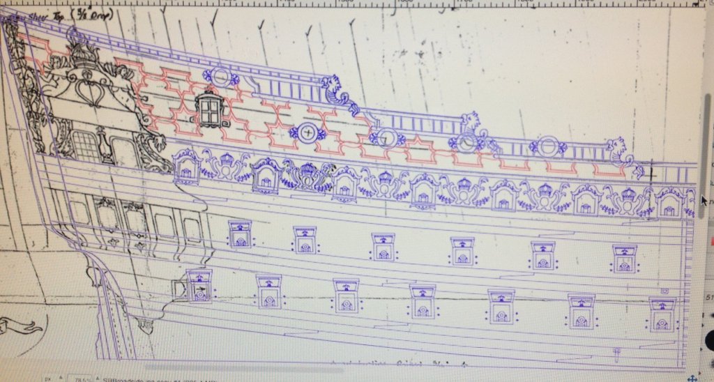
EJ's post got me thinking about what the artist sees and what he draws and, specifically, about the Berain stern painting. I think that there is an obvious artistic distortion that has been perpetuated as an engineering distortion. Maybe this is well known, but I haven't seen it discussed. Here is the painting. To improve clarity and detail I cropped and enlarged the QG section, then converted to black/white and adjusted the contrast. To me it looks like it was painted from an angle off the starboard stern. The way the size and angles of the lower lights diminishes towards the bow edge of the QG, the different perspectives of the dolphin pairs that flank the upper windows, and, most of all, the way the forward edge of the QG seems to overlap the two middle gunport openings. No shipwright would have built such an unworkable port once, much less twice. But it is exactly what an artist would see as the bulge of the QG obscured the ports. So, with the starboard aft corner of the ship being closest to the artist, it's size, and especially its height, would be increased by the optical effects of parallax. This artificially raises the rail and increases the sheer. It also increases the angle of the QG windows. Of course they do not necessarily match the sheer of the interior decks, as indicated by the lines of the gunports, but would the decks of the galleries really be so steep for the admiral and captain? The problem is that the painting is presented as though it was seen from directly athwartships. As though it is an engineering drawing without perspective. Unfortinately, the parallax issues were not adjusted and therefore any plans drawn over the painting will incorporate them. I suspect that the Heller kit does, too. To get an idea of what adjustments could be made, I did a little fooling around with the image. I put the picture into Photoshop and used the 'distort' function to put in about a 10 degree angle to a vanishing point at the horizon line. Here is how it came out Immediately the sheer dropped, the galleries leveled, and even the hull decorations took on a squarer, more regular appearance. This may not be the precise amount of parallax to correct, but it is a start. To see what this might look like with a larger area of the ship, I went to Marc's plans. Here they are without adjustment And here after putting in a similar distortion angle Finally, to see what effect this might have, I cropped out the QG from the adjusted drawing And dropped it onto Marc's distorted plans. Although this is just some doodling around, and without adjusting the designs and angles of the QG, I think it sits pretty well. Marc - I know that you are kit bashing the Heller, so you may be locked into its design, but this may be a consideration when you go to scratch-building your own. Or I could be completely wrong. LOL ! Dan

- 2,699 replies
-
- 5
-
-
- heller
- soleil royal
- (and 9 more)
-
Hi Marc - Those plans are getting better all the time. Tracing the Berain drawing is a good idea, but the sheer looks to be exaggerated, especially at the upper rail. Maybe the artist did this as an attempt to show perspective, because there seems to be a progressive tilt from deck to deck. If so, maybe your GIMP program has a "free transform" or similar function that would allow you to pull down just that corner to make it match your space a bit closer. Also, I just ran across this discussion of the Heller SR kit when I went to renew my subscription to FineScale Modeler. Don't know if you have seen it. http://cs.finescale.com/fsm/modeling_subjects/f/7/t/68138.aspx The discussion ran from 2006 to 2011 and was dominated by Dr. John Tilley, professor at East Carolina University and former curator at the Mariner's Museum. He hated the kit, though he built one. Lots of links in the discussion to some pretty well built examples. Judging from those, it can be turned into a very nice looking model. But the effort to do so is tremendous. One link I read said that it had taken the builder 14 years to finish, mostly in research and correcting kit problems. Whew! I don't have that kind of dedication. With all the research and work you are putting in, yours has all the makings of being one of the best, despite any non-correctable kit issues. Dan
- 2,699 replies
-
- 2
-
-
- heller
- soleil royal
- (and 9 more)
-
That knife is looking good! Maybe you can go on "Forged In Fire - The Miniature Show". I experimented with your pencil grip and found that even using a generic hobby handle armed with a #11 blade I could get clean, well-controlled cuts through thin sheetwoods of several species. Thanks for showing it. Dan
- 714 replies
-
- 3
-
-
- lady nelson
- victory models
- (and 1 more)
-
What an excellent discussion of your process. I may never make a knife, or its handle, but the story of your perseverence is inspiring, whatever the subject. Hope your wound is recovering nicely. Dan
- 714 replies
-
- 2
-
-
- lady nelson
- victory models
- (and 1 more)
-
Keith - What great metalwork ! I would be proud to own a yacht with fitting half so nice. Dan
-
Doris - What a great artistic eye you have ! Thanks for sharing your techniques and photos. Dan
- 1,035 replies
-
- 4
-
-
- royal katherine
- ship of the line
- (and 1 more)
-
Marc - It seems that my little seed has turned into quite the thicket. Sorry if I have caused you a bunch of extra work, but it seems that public opinion favors insanity. Don't worry, I am sure that I have a spare straight jacket in my closet for you, and I can tell you from personal experience that the rubber room and the shock therapy are not as bad as they seem. Ad astra per lunacy. Dan
- 2,699 replies
-
- 3
-
-
- heller
- soleil royal
- (and 9 more)
-
Maybe you could try the easier method of straightening the gunport sides on one or two ports. If you don't like the look, you can either backfill to the original configuration, or go with the insane amount of work needed to replace all of the surrounds. If you have truly lost your mind and decide to go the replacement route, you could consider 3-D printing for the surrounds. You could make up one in the computer, then copy it multiple times and attach them to each other with sprues to form a sheet which can be printed by Shapeways or other inexpensive service. In either case, I will be watching with interest. Dan
- 2,699 replies
-
- 2
-
-
- heller
- soleil royal
- (and 9 more)