HOLIDAY DONATION DRIVE - SUPPORT MSW - DO YOUR PART TO KEEP THIS GREAT FORUM GOING! (Only 24 donations so far out of 49,000 members - C'mon guys!)
×


shipmodel
-
Posts
941 -
Joined
-
Last visited
Content Type
Profiles
Forums
Gallery
Events
Everything posted by shipmodel
-
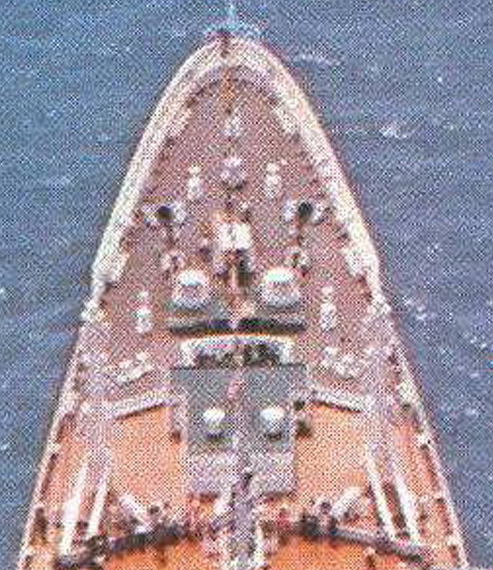
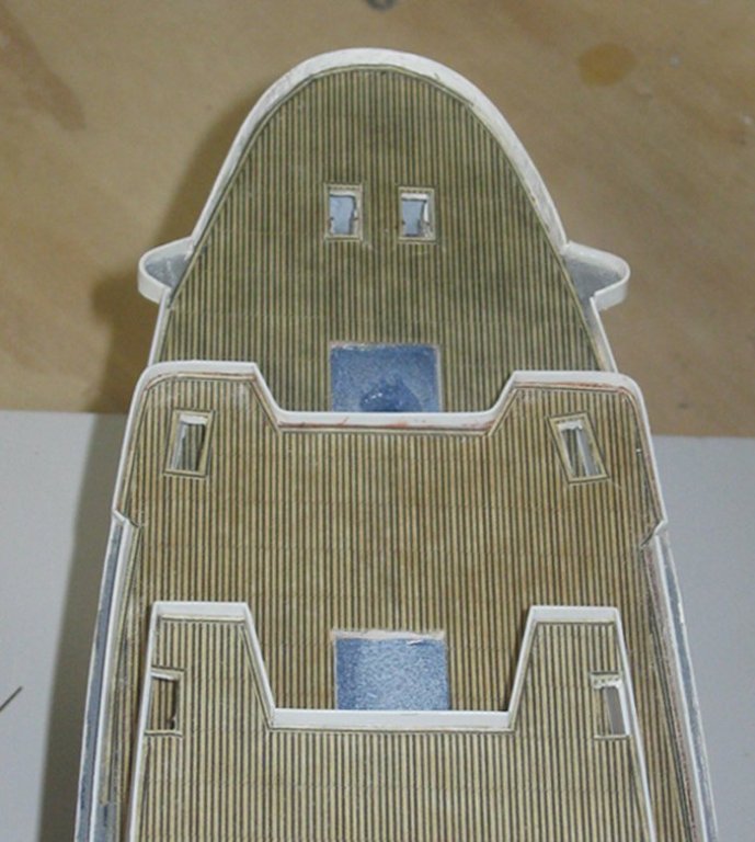
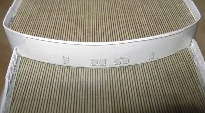
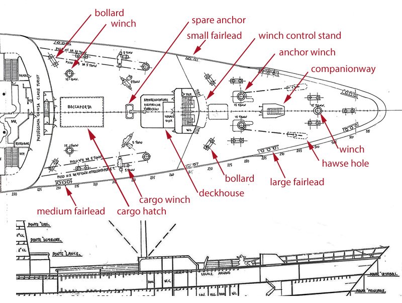
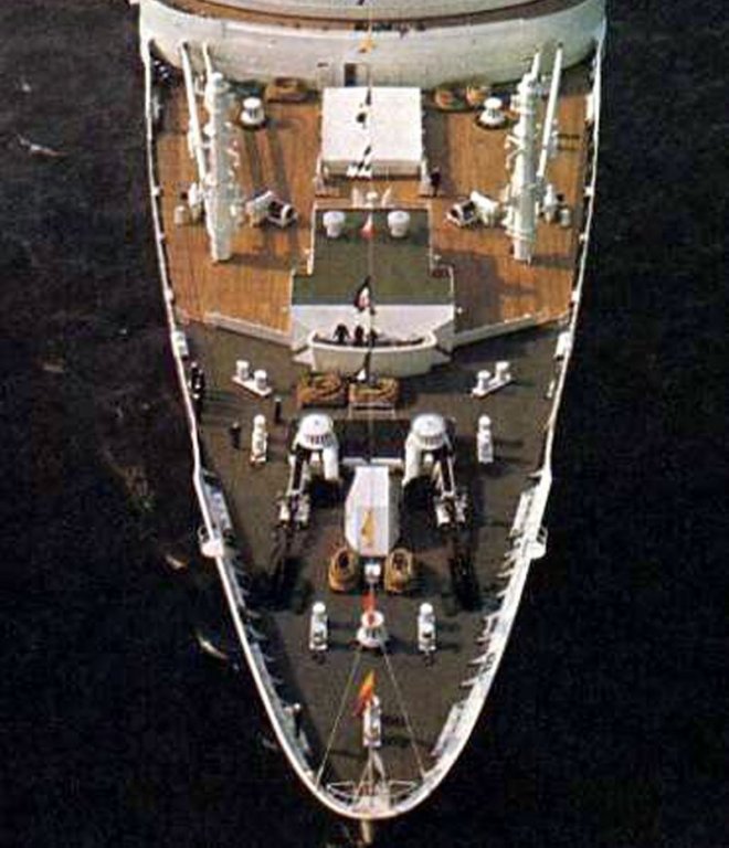
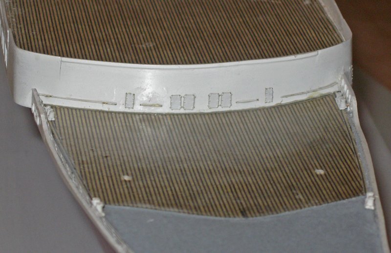
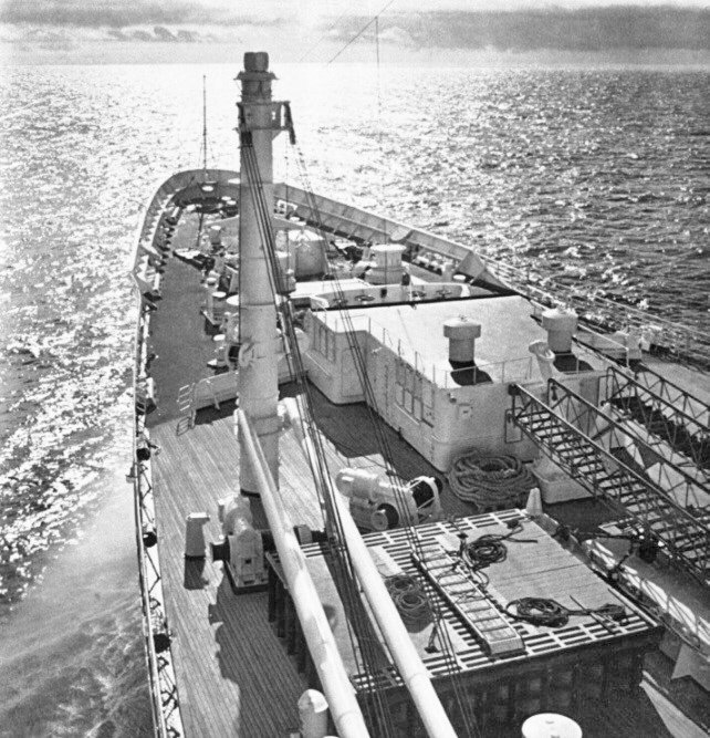
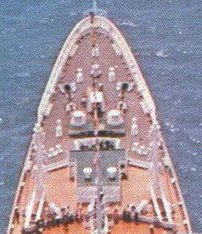
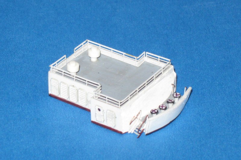
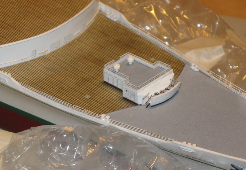
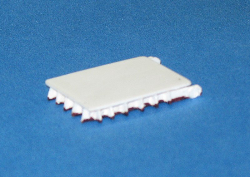
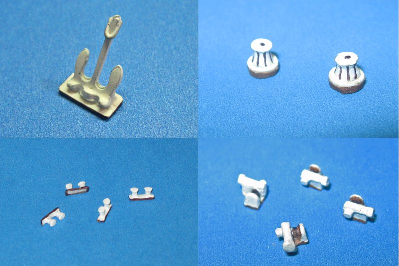
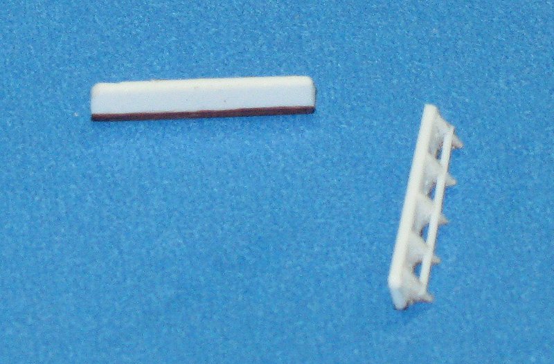
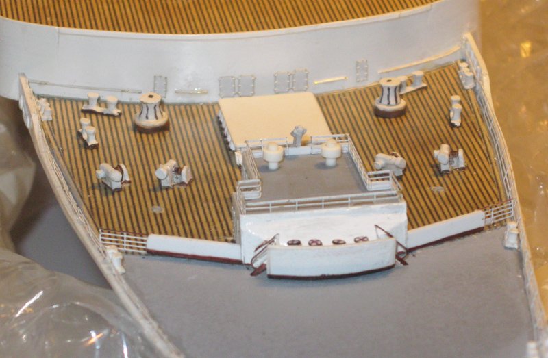
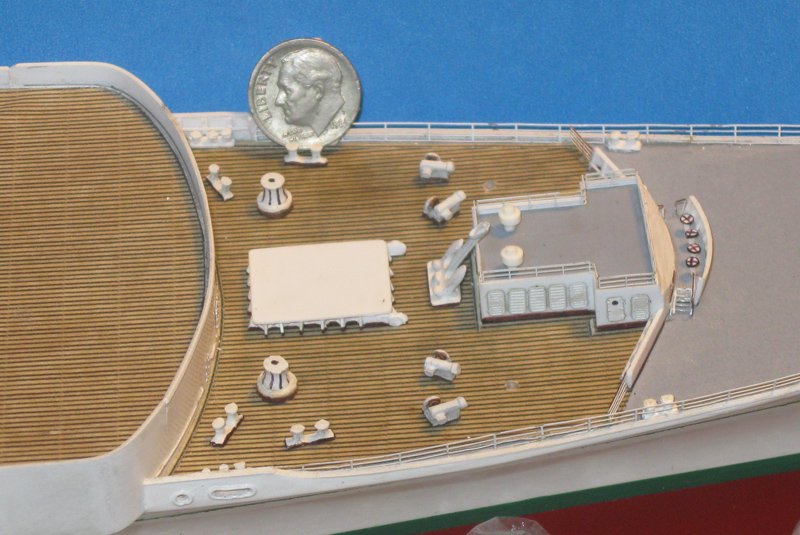
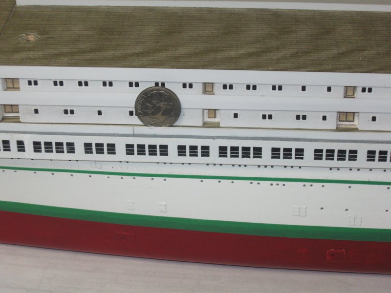
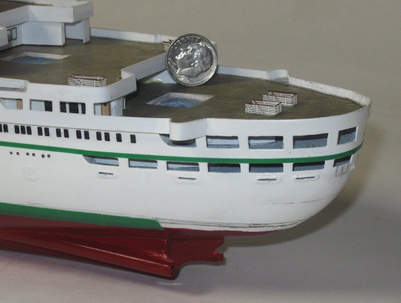
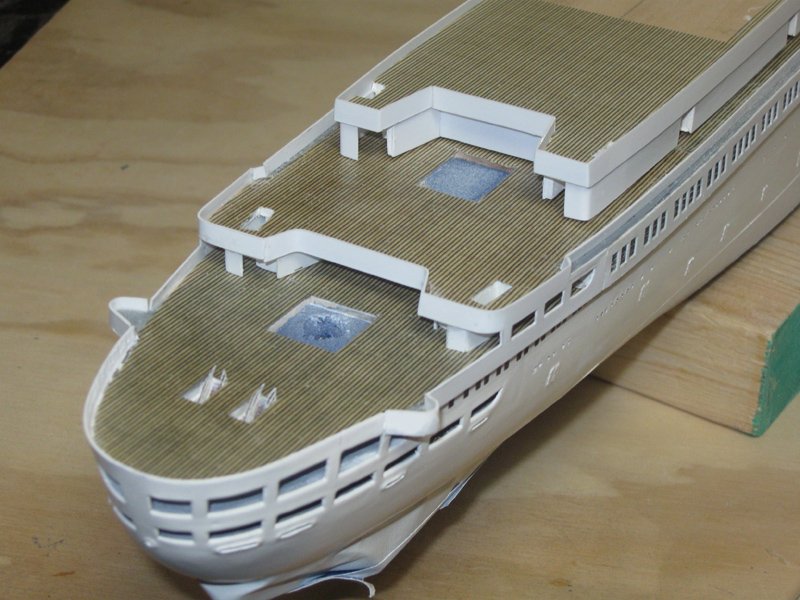
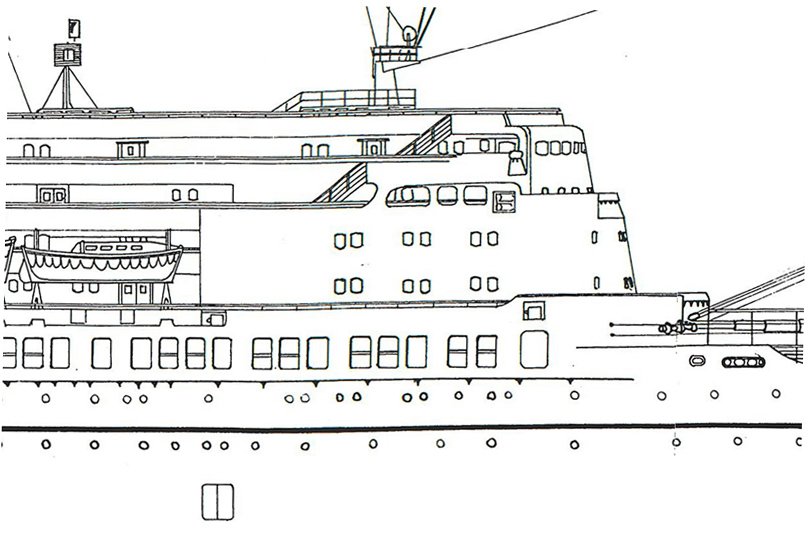
 Hi all - It was really nice to see several of you at the NRG conference in St. Petersburg last weekend. The conference was very enjoyable with lots of good models, informative talks and roundtable demonstrations. And, of course, it is always great to see and chat with modelers whom I would only otherwise know as a screen name. With the lower hull done I could start adding details to the decks. Many of the elements have already been prepared while I was working on the hull. The first details to be added were the margin planks around the edge of each deck and deck openings. Here you can see this around the fantail deck, Promenade and Upper decks, and the stairway openings in the three decks. The difference is striking when you compare those to the stairway openings in the topmost Lido deck, which have not been done yet. The margin planks are made by carefully slicing one plank from the sheet of paper decking with a metal straightedge and sharp blade. The ends of the strip are miter cut diagonally and softened with a misting of water before being attached with pH neutral white glue. This is only done where the margin plank crosses the line of planking. Where the opening is along the planking no margin plank is used, since the eye cannot distinguish their absence without significant magnification. At the bow a margin plank was installed along the edge of the working deck to set it off from the gutters that border the bulwarks. Another was carefully worked into a curve around the base of the Promenade deckhouse. These planks are barely visible, but without them the deck looks unfinished and the deckhouse seems to float above the deck below. Now I turned my attention to the machinery and fittings of the working deck at the bow. From the plans you can see how many different kinds there are. The side view does not have a great deal of additional information, but it shows how tall the deckhouse and other elements are. However, many of the fine details are not shown on either plan. To fill in the gaps I found a number of high resolution photographs which together show almost all or portions of the deck and the fittings. Here is one of the most useful ones showing the entire layout. It is even in color. You can clearly see the separation between the wooden deck with the cargo winches and hatch, and the composite deck with the anchor winches and ground tackle fittings. The first bit of detail that I started with is not shown on any of the plans, but in the photographs it is clear that there is a metal handrail across the face of the Promenade deckhouse between the several doors. I made it from .011” wire which was straightened by rolling between two hard surfaces. The pieces are attached with small drops of cyano fed to the wire with a toothpick as I hold it in place. After I was satisfied with their placement, the handrails were painted with clear finish to help hold them secure. Along the edge of the deck there is a scallop in the bulwark that is protected by a metal railing. Photoetched 4-bar railings were sourced from Gold Medal Models and sprayed white. On each side the railings were test fit and adjusted so one section set up just where a small fairlead had to sit, just forward of the wooden deck. The lower two bars of each railing were carefully cut out at that location and secured with both cyano and white glue. The 2-post fairleads, like the larger 3-post ones, were originally Bluejacket metal castings that underwent some radical surgery before being filed and sanded to final shape. On deck, the major eye catching element is the deckhouse. The plans only give a general idea of how it looks, so I turned to various photographs that had sufficient resolution to help. They gave me almost all of the details, and I puzzled out the rest. Here is how it came out. The most complicated area is at the forward end where the structure is not only curved, but angled as well. This face leads to a winch control platform with four handwheels on stands protected by a breakwater that not only curves, but is angled forward. Small sets of steps lead up to this platform from either side. The sides have doors and what appear to be awnings that can be opened if desired. The roof has a photoetched railing and a pair of ventilators made from styrene rod and tube. At the base you can see a brown edging. This was a feature of almost all of the structures, railings and bulwarks on the ship. It was applied with an indelible marker and overpainted with a clear finish for protection while handling and for UV protection on the model. Here it is installed on the centerline of the deck. It had to be very precisely located, so slow setting white glue was used which gave me the time to adjust and readjust. Once it was securely in place the back and wing edges were defined with margin planks. The next major fitting was the large cargo hatch aft of the deckhouse. Like the deckhouse, the overall size and shape were taken from the plans, but the details of the angled support pieces and the lifting mechanism were taken from photographs. (Sorry that the photo is a bit out of focus.) Most of the other elements started life as Bluejacket castings, but were extensively modified and/or cleaned up before painting and mounting. Here are (clockwise from upper left) the spare anchor, the large round winches, four small cargo winches, and a set of bollards. The final elements in this area, other than the cargo boom cranes, were the breakwater wings that extend from the sides of the deckhouse towards the bulwarks. They were built up from styrene strip with triangular buttress supports and a horizontal bar that was cut into the supports. The cargo cranes stick up and would be in danger of being broken off during construction, so they were left off until a later time. So here is that area with all its fittings in place, including the railing gates at the ends of the breakwater. And for size comparison, here is the area with my patented 6-inch diameter dime. Next, the fittings for the forward part of the working deck. Until then . . . Be well Dan
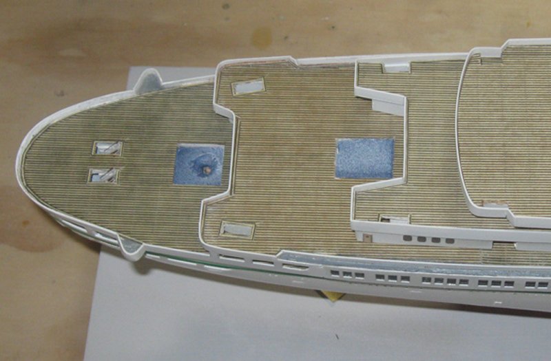

- 287 replies
-
- 10
-

-
- michelangelo
- ocean liner
- (and 1 more)
-
Hi Marc - Nice ingenious solutions to the problems of lengthening and widening the stern. They should work out well and the surgery should be invisible in the final model. Well done, mi amigo. I still have a problem with the outward flare at the top of the taffrail, but we have been through that and I respect your decision. See you soon. Dan
- 2,696 replies
-
- 3
-
-
- heller
- soleil royal
- (and 9 more)
-
Hi Chris - Looking forward to following your progress from the beginning. With such an ambitious building timeline it should be quite the project. One small word of caution - as much as I respect the work and scholarship of M. Budriot, I have found some significant issues when working with his monographs. He has a tendency to re-use his drawings from the 74-gun ship project for designs of smaller ships by simply reducing them in size, without taking into account the fact that humans cannot be similarly reduced. So check headroom clearances, ladder riser heights, and similar details before incorporating them into your model. Best of succcess. Dan
-
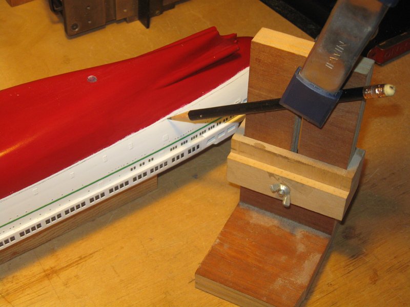
Hi again – Just a quick note. In the last segment I was uncertain about how the stern access doors were represented. Even though they are just 2mm x 4mm, the dark lines were visibly jarring. Others noted this as well, and one sent me a private message with his opinion that the doors did not match the quality of the rest of the work. He was, of course, correct. Taking that to heart, I removed the inked lines and, after several experiments, replaced them with lines drawn with a sharp, soft pencil guided by a flexible straightedge. Below, the before and after photos. I think you will agree that the look of the doors has been substantially improved even if, under magnification, they are still not perfect. On a side note, I want to thank the modeler who was brave enough to put forward a criticism of my work in a timely manner. Although I do appreciate and cherish the compliments and likes, we are none of us perfect. Certainly not me. So if you do see something that you think can be improved, please, Please, do not keep it to yourself. If I have stopped at ‘good enough’ I need my feet held to the fire until I go back and make it ‘good.’ PS - since I saw it under magnification, I removed the little green tab that sticks up from the green sheer stripe just to starboard of the doors. Not a big change, but I felt better after doing it. Thanks again. Dan
- 287 replies
-
- 8
-
-
- michelangelo
- ocean liner
- (and 1 more)
-
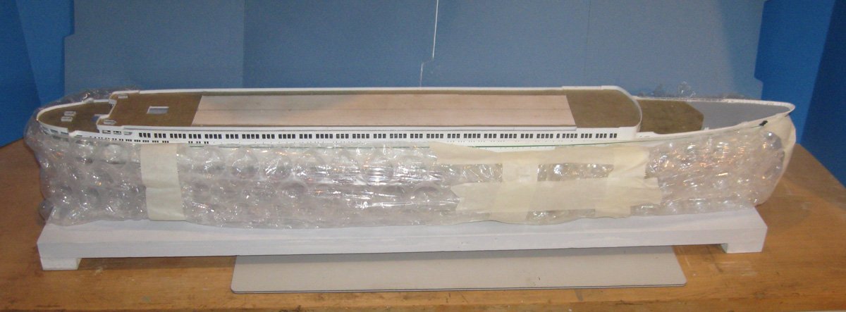
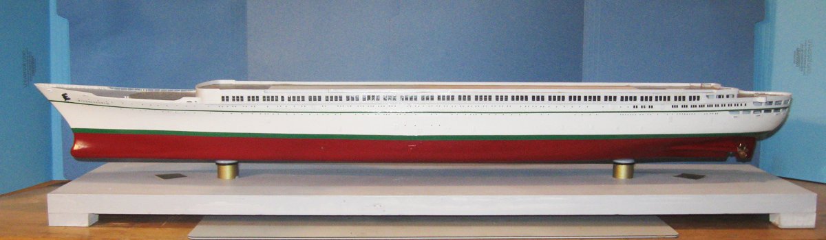
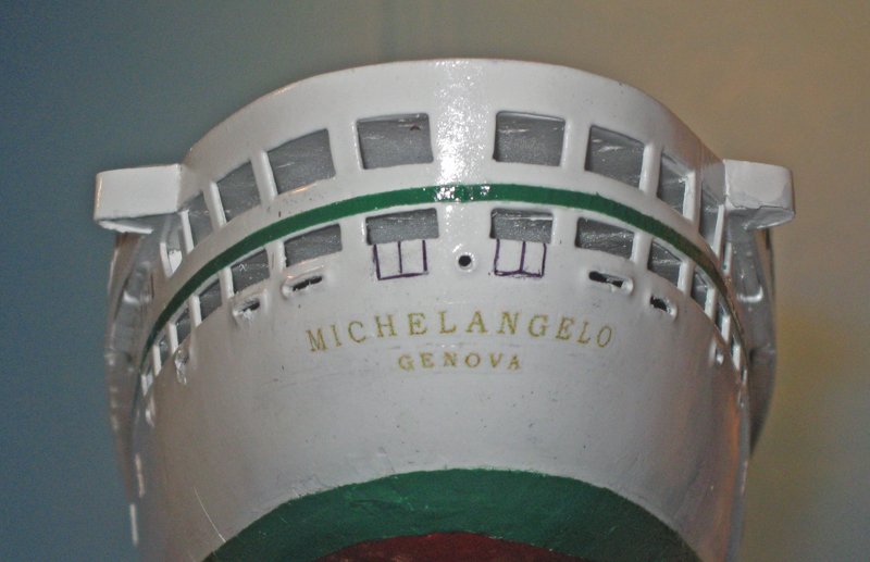
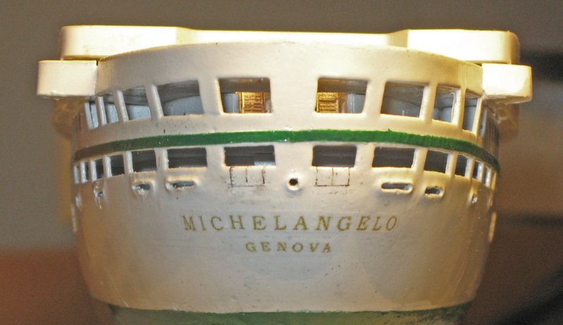
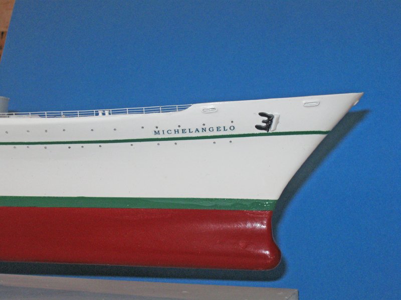
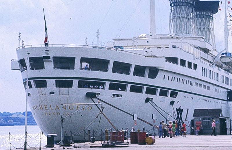
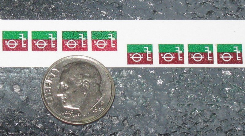
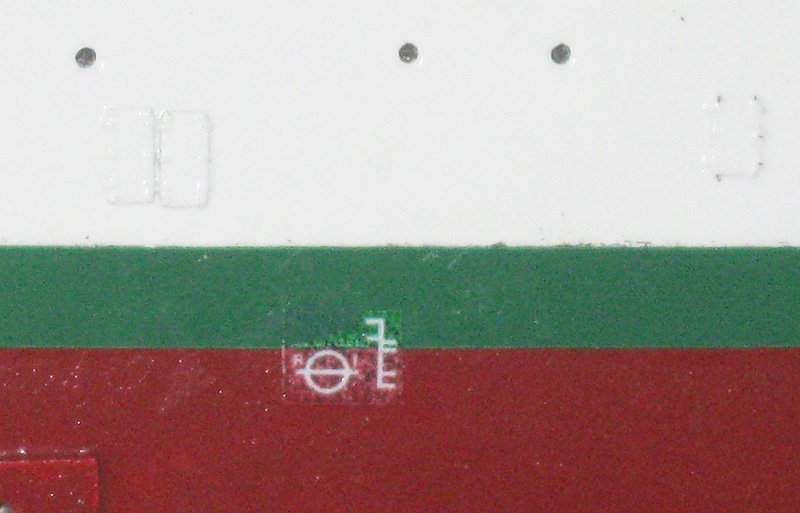
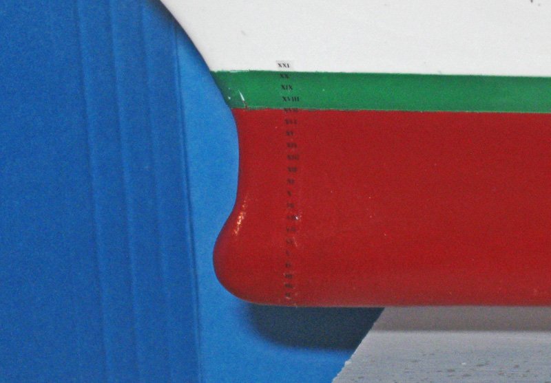
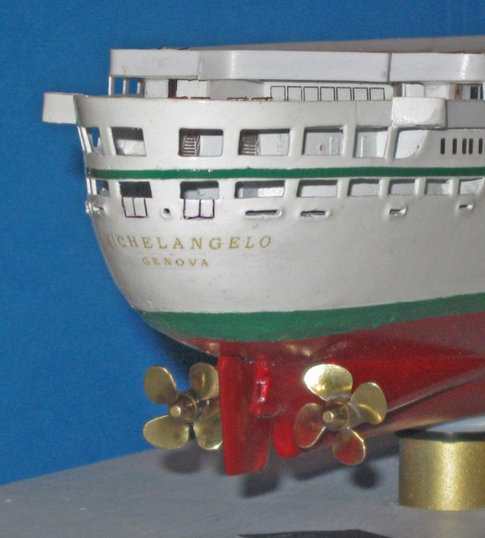
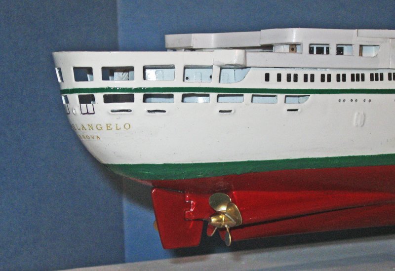
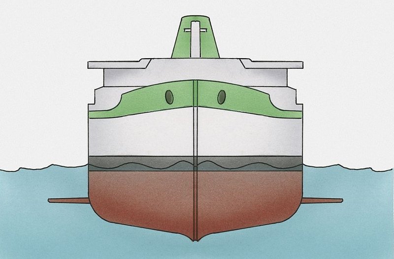
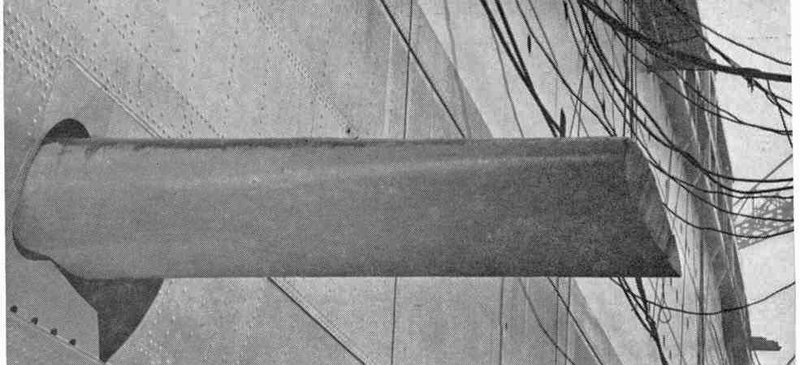
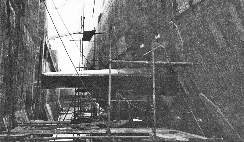
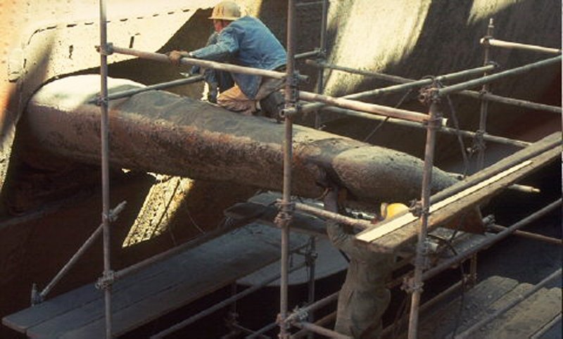
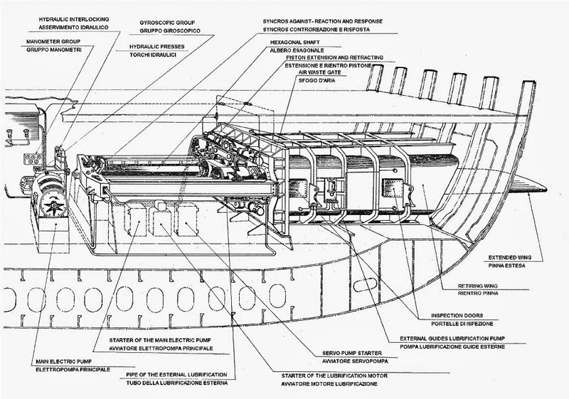
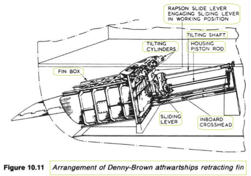
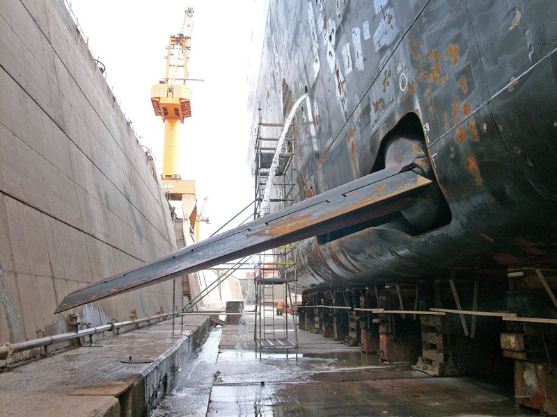
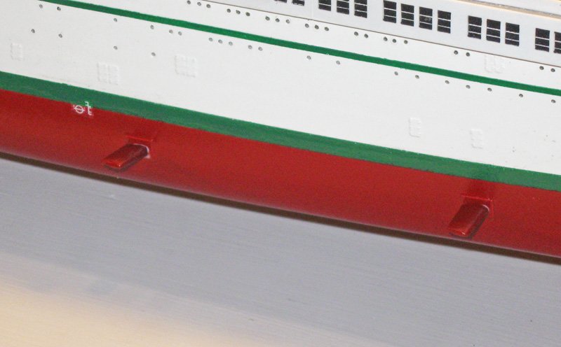
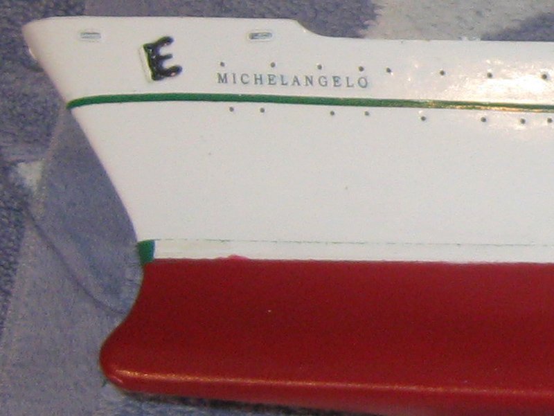
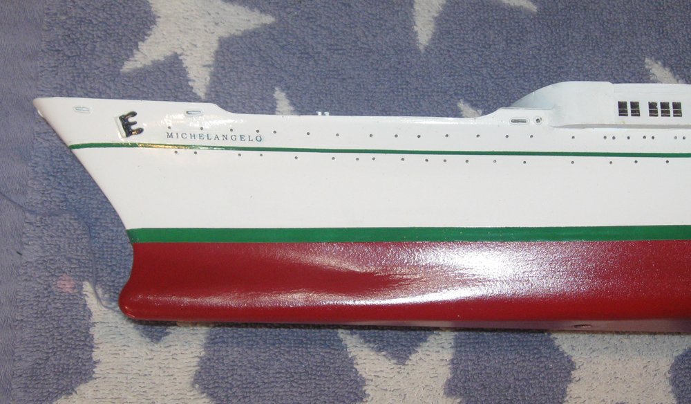
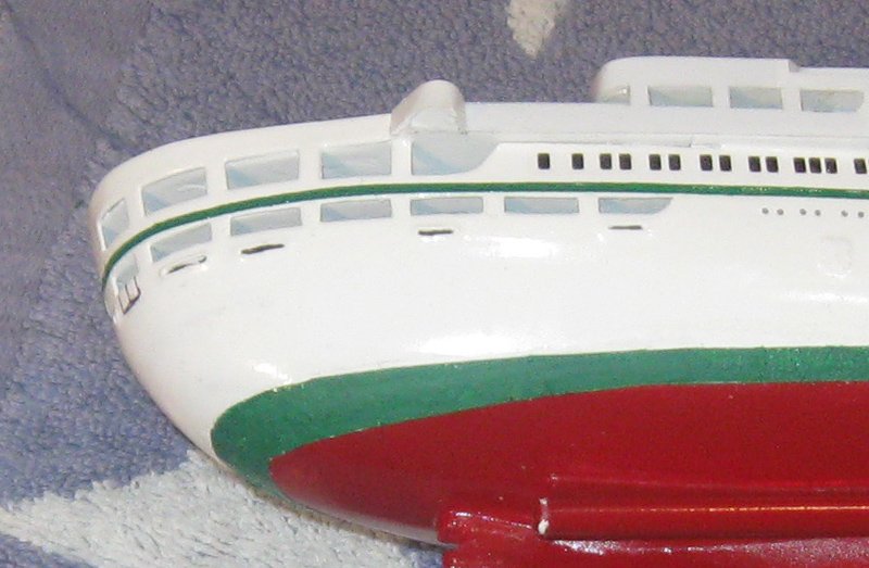
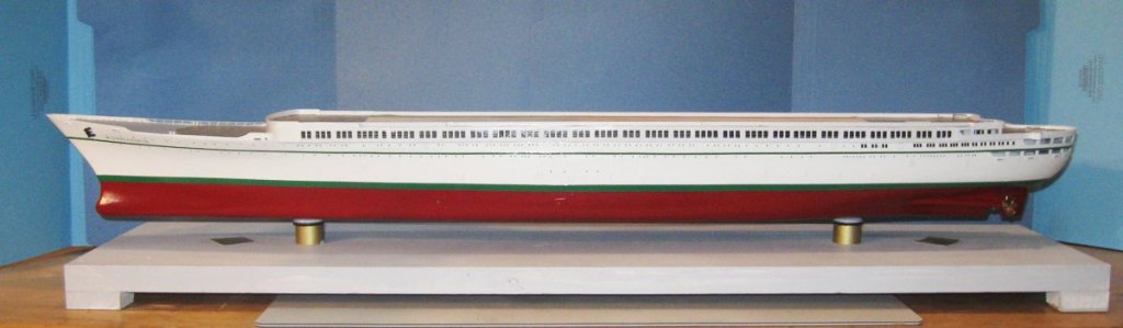
Hello again to all – A rewarding installment this time. No major problems at all as I finished the lower hull. While I was waiting for various deliveries during the boot topping odessey I worked on the hull details. The first were the two stowed anchors. These started life as Bluejacket castings, but were cut and ground to proper shape as shown in photos of the ship. They are not inset into the hull, as on most liners, but mounted on a triangular cleat and held with the stock in the hawse pipe. The ship’s name is a decal made on my ink-jet printer using a white decal sheet made by Testors. Clear sheets also came in the packet, but my printer works less well on it than on the white. You may have noticed during the last installment that the name appeared and disappeared out of sequence. That was because several were made, tested and rejected for one reason or another. It is not difficult to remove a bad decal with a little more water if it has not been overcoated with finish. This is the final one. At the stern the ship name is not done in black, but in gold. You can also see the outlines of the two sets of stern access doors that were mentioned earlier in the build with rust streaks coming down from the corners. The doors were simply inked on with an ultra-fine tipped marker. In the photo they look a bit too bold, so I may yet adjust them. The name and home port of Genova are decals. To get them to curve around the stern I scored between each letter through the decal film but not through the paper backing. I left a small band at the bottom to hold the letters at the right distance from each other. With careful manipulation with a small paint brush and a toothpick each letter was adjusted around the curve. Decals were made up for the plimsol mark. The mark is correct for ships flying the Italian flag, but at less than 10mm overall the letters “R” and “I” which denote the country are so small as to be almost beyond the abilities of my eyes, much less my printer. Several copies were made then varied slightly in tone before being printed out so I could select the closest match. Once the decal was applied and had dried the edges were overpainted with a bit of red and green decanted from the rattle cans. Decals for the depth marks had to be tiny Roman Numerals. They are beyond my printer, so they were ordered and installed. These were the last decals for the hull, so everyone was snugged down with setting solution and overcoated with clear varnish to secure them permanently. A pair of 20mm diameter counter-rotating brass propellers were sourced from Europe. A quick polishing with jeweler’s rouge on a felt cone and they were secured into the prop shaft tunnels that were tipped with brass collars. The rudder shape was taken from the plans and cut from 2mm hardwood. An airfoil profile was sanded into it from fore to aft. It was notched to fit the rudder hinge on the hull and a hole for a brass pin was drilled up through the rudder and hinge and into the hull. After a few coats of primer and final sanding it was painted to match the lower hull and installed. The final items on the hull are the fin stabilizers. These are small wings that take the place of the bilge keels to keep the ship from rolling. They were first reported on a Japanese cruise liner in 1933. As fixed wings they were not very successful, and were supplanted by gyroscopic stabilizers. These were too large and heavy, so they in turn were supplanted by automatically adjusted fins. It is known from newspaper reports and articles in engineering magazines that the Michelangelo had adjustable fin stabilizers, but none of my photos of the lower hull have any visible fins. I was never able to find more details, not even how large they were. Some fins are very small, and some very large, and some in the middle. Most stick out horizontally from the hull, but some angle down perpendicular to the curved hull. All modern ones are retractable to allow closer docking without the danger of damaging the fins. Some slid straight into the hull, while others, like the one in the photo, folded into slots in the hull. I found some drawings of the internal machinery of the retractable fins, and two are here just because I thought my audience would appreciate them. I made my fins from 2mm hardwood sanded to an airfoil shape and tapered from the hull outward. They are 5mm wide and 12mm long, which fits with the general appearance of fins in photos, and with my eyeball of what looks right for the size of the model. They are mounted horizontally in brass sleeves inserted in the hull. The lower hull is now complete and the model was firmly attached to its building base. This will be replaced with a presentation base once the model is finished. In the meanwhile, the fins were removed to safe storage and the lower hull protected in bubble wrap while work on the upper decks continues. So it’s off to the NRG conference in Florida. Hope to see many of you there. Be well Dan


- 287 replies
-
- 12
-
-
- michelangelo
- ocean liner
- (and 1 more)
-
Le Soleil Royal by Nek0 - 1/72 - Marc Yeu
shipmodel replied to Nek0's topic in - Build logs for subjects built 1501 - 1750
Magnificent, Marc. Your pre-planning of every piece is resulting in a truly outstanding build, first time or not. I am even more impressed by your dedication to such small details as making square bolt heads. Inspiring work. But is that Darth Vader standing next to your row of cannon? Do you have a battalion of tiny storm troopers who are actually doing the work? If you do, that's even more impressive. Dan Dan- 208 replies
-
- 5
-
-
- le soleil royal
- 104 guns
- (and 2 more)
-
Thank you all for the support and kind words. Love it though I do, there is only one thing more frustrating and rewarding than ship modeling, and that is golf. I have spent many masochistic hours chasing a little white ball around beautiful grassy fields. And into the woods, and streams, and sand traps. Now I do this. What was that definition of insanity again? Dan
- 287 replies
-
- 6
-
-
- michelangelo
- ocean liner
- (and 1 more)
-
Magnificent work, Keith. Your attention to detail and accuracy are inspiring. Your results are amazing. I am sure that you mentioned it before, but what is the purpose for the openings in your deck? Will there be any problem working on them with the sails rigged? Dan
-
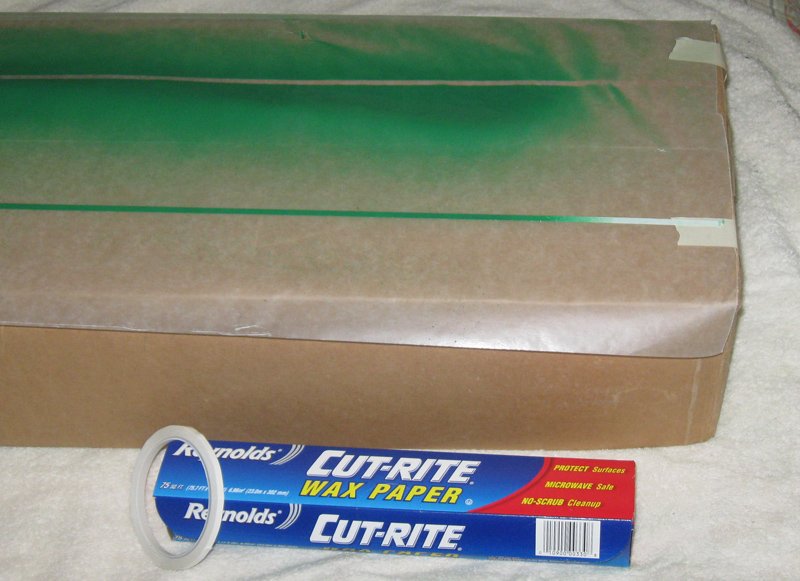
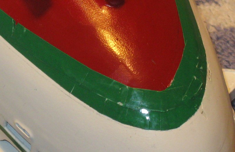
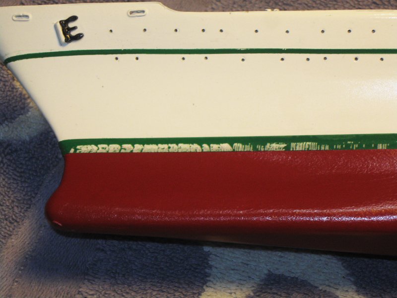
Hi again to everyone looking in - Thanks as always for the likes and compliments, and to all who made suggestions for my boot topping problem. I believe that it has been solved, but not without lots of backpedaling and redoing. Here is how it went – When the last segment closed I had the Promenade deck structure done and was working on the upper decks. The upper hull had several coats of gloss white and the narrow green sheer stripe had been successfully applied using 1/16” green vinyl pinstriping tape which is made for the car detailing market. The next element was the wide green boot topping. I sourced 3/16” vinyl striping tape from the same people who made the 1/16” tape so the colors would be identical. The vinyl is somewhat flexible and here in the midships area and at the bow I did not have any trouble laying it down along the waterline. There were, however, several problem with the tape. First, it was too thick, measuring out at .008. It was not very noticeable, but in glancing light the raised edge could be clearly seen. A bigger problem was that despite its thickness, it wasn’t really opaque, and the demarcation line where the red and white met was visible through the tape. Not a lot, but hard to miss once you see it. But the biggest problem was that it was going to be very difficult to do the area under the counter. Due to the curvature of the hull the boot topping has to bend in three dimensions and, to keep the same vertical distance, has to get wider as well. The vinyl tape could not bend to fit the curves, and the thickness would make it lumpy if it was layered to make up the added width. I could have tried to cut and piece it in, but with the other problems I decided to scrap this product. With some care I pulled the tape off the waterline only to find that it left green residue along the edges. RATS ! Fortunately, it was removable with mineral spirits on a cotton swab. And while I was at it I cleaned the entire hull, removing all my pencil marks as well. To replace them I carefully mounted the model upside down so the keel was perfectly parallel with the work table and the stem was perfectly vertical, or as perfectly as I could make them. Then I used and old waterline marking jig that I made about 25 years ago and kept around ever since. A sharp point on a soft lead pencil did the actual work. To replace the boot topping I located and ordered some striping tapes that were described as being very thin, and some Tamiya masking tape that is meant especially for curves. While I was waiting for delivery, I tried Druxey’s suggestion of making thin paper strips. I used the thinnest paper I have, some art quality tissue paper. I could, with some care, cut strips with parallel clean edges. These were misted with water to relax the fibers, then I laid out the strip on the hull without glue. The water was enough to make a temporary bond. The results for me were uninspired. I could lay out the tape fairly well, and could move it around with some additional wetting, much like a water-slide decal. But it never laid down completely on the curves, even some of the smoother ones, much less the tight curves in all three dimensions under the counter. Maybe it was my paper. Maybe my technique. Whatever, it would not work for me. It would all have to be removed and discarded, along with the work invested. DRAT !! But as long as I had the paper tape in place on the hull, I tried masking both above and below in preparation for spray painting the green boot topping. The Tamiya tape had not arrived, so I cut long 1/8” wide strips of painter’s blue tape and laid it above and below the paper strips. This, too, was not completely successful. No matter how careful I was, I could see that there were small crinkles in the edge that would let paint bleed underneath, even after painting with a clear finish. The masking tape would have to be discarded, along with the work invested in laying it down. BOTHER !! Finally the thin striping tape arrived. It was Chinese, of course, and I had to buy 5 rolls in 5 different colors of 40’each, none of them green. But it was only .002” thick, which was promising. I used the white tape and laid out strips about 8 inches longer than the model on a length of waxed paper. They stuck well, but came up easily enough when tested. They were spray painted green from a rattle can. Repeated light coats were laid on till I was satisfied that the tape would be opaque. After drying overnight I carefully lifted the ends of a strip and pulled it up, only to find that the dried paint was stronger than the bond to the waxed paper. Attached to both edges of the striping tape were flaps of paint, some large and some small, but more than enough to ruin the tapes and they all had to be discarded. GRRRRR !! For the next set of tapes I made them a bit longer, but did not paint all the way to either end. When I was happy with the depth of color the tape was removed while the paint was still wet using the unpainted ends. It was immediately stuck back down on a clean section of the waxed paper and allowed to dry. The next day the tapes were carefully set along the penciled waterline. They were lightly pressed against the hull until I was satisfied with their placement, then burnished down. I finally had a clean, crisp, boot topping in the right color with a tape that was barely thicker than a coat of paint, and - - - next time - - - will be easier to achieve. Under the counter there were still some issues. With the tape so thin I could layer it over itself without major lumps, but it still would not bend, so a good deal of piecing in was required. The photo looks worse than the actual model because I have already hardened the tape with clear varnish and have started to sand the overlaps smooth, which accounts for a lot of the white areas and lines that you see. Once the sanding was finished I hand painted over the tape with green paint decanted from the rattle can. This not only evened out the surface, I could fill in the small angles to make a smooth curving edge. The final result was, I think, more than satisfactory, even under photo magnification. WHEW ! Now that I had the boot topping done I did a final light sanding of the lower hull which had picked up some scratches and blotches while I was working elsewhere. After sanding and wiping it down, I masked off the boot topping with the Tamiya tape made for curves. I have to say that I am a fan of the product. It laid down easily, could be repositioned as needed, and went around the curve under the counter without a problem. I burnished down the edge, then built up the rest of the masking in layers of widening strips of painter’s tape until the entire upper hull was protected. I sprayed a clear coat along the edge of the masking, as several of you suggested, then laid the model on its side to spray the red from over and behind the masking so the paint would not be driven against the edge. I used light coats and only did one side at a time, giving each a full day to dry. When I removed the tape I had no bleeding under the masking. But I did have THIS - - - The Japanese masking tape had pulled up the American paint from all along the Chinese striping tape. I wonder if this says anything about global geopolitics? In any event, all of my hard-won boot topping would have to be removed and discarded. There was only one thing I could say – When I got back to it after a few days to clear my head the repairs went fairly quickly. I managed to save the boot topping under the counter with minor touchups of paint, and the rest of the tape came off easily and without leaving a residue. I was now proficient in making up the tapes and applying them, so only two days later I had restored the boot topping satisfactorily. So I guess I learned some valuable lessons in perseverance and dealing with frustration. But I would much rather skip that class next time. LOL ! Be well. Dan


- 287 replies
-
- 18
-
-
- michelangelo
- ocean liner
- (and 1 more)
-
Hi Nils - I am really enjoying following your build. Those barrels look quite lifelike. Excellent work. I do have some reservations about the gun carriages. To me they look very small and light compared with the size of the guns. Also, the trunnions are usually bedded down into the cheeks of the carriage so the recoil force is directed down into the wood. Before you do a lot more work on guns, you should check some sources. Dan
- 692 replies
-
- 3
-
-
- eagle of algier
- chebec
- (and 2 more)
-
Hi Cedric - A very nice start. You are setting yourself a very hard task, kit-bashing to such a great amount. I am watching with real interest. I do have a bit of confusion about your calculation of the the distance between gunports. You have divided the hull into 17 equal segments, including the one from the forward port to the stem and from the aft port to the stern. I am not sure that these two distances were the same as the separation between gunports. I am no expert and I would not be surprised if I was wrong and they are the same as the gunport separation. But to me it just doesn't feel right. Would it make sense to locate your forward and aft ports where they fit, depending on the sizes and locations of the quarter gallery, headrails, etc., then divide the space between the two by 15? That would give you the distance from center to center, rather than the planking distance between ports, but that is just a technicality. Dan
-
Outstanding, Michel - I would be tempted to frame it and call it a day - LOL !! Dan
-
Patrick - Thank you for showing your carving of the figure. It is a miniature masterpiece in its own right. I was also impressed with the ingenuity of how you made the scale stave that he is holding. Brass rod and insulation - genius! Dan
-
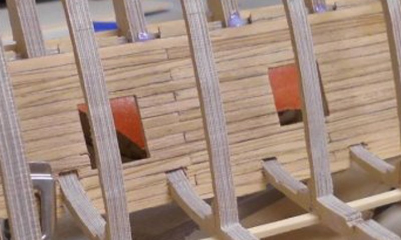
Hi Clare - Fascinating. It reminds me a bit of the mortice and tenon construction of early Mediterranean boats, as well as the laced planks of Egyptian boats. Am I right in interpreting the photos to show that the butterflies go all the way through? Won't that cause weak points, especially where the butterflies are close together? Dan
-
Hi Nils - Really nice work on those spindles. The framework is coming together well. I can almost see her scudding across the waves. The gratings are nice and clean. The deck planking is coming along too, but I have a small issue with the three butt joints in the short planks between the gratings. Although they fit in with your planking pattern for the deck, I don't think a ship builder would add in an extra joint unless he was really short of wood. It's a really small point, and this deck will rarely be seen, but it's something to keep in mind for the upper decks. Dan
- 692 replies
-
- 11
-
-
- eagle of algier
- chebec
- (and 2 more)
-
Patrick - Thank you so much for posting your build of Renommee. You are doing excellent work and I look forward to following and learning from your experience. The scale figure is wonderful. Is it carved from wood, or other material. Dan
-
Bob - I have some thin white striping tape coming, which I was going to paint green and try to apply. After your suggestions, i will add some coats of clear on top for strength. Marc - I have some Tamiya masking tape for curves coming, and will try to do the masking that you suggest. Or I will gladly ply you with Maker's Mark after you have done the masking for me. Druxey - Failing everything else, I will cut a nice horizontal line across my forehead and slip in a layer of green jello as a boot topping. By then my brains will have turned to goo anyway. Later Dan
- 287 replies
-
- 5
-
-
- michelangelo
- ocean liner
- (and 1 more)
-
Hi Bob - I have some decal film, but did not think that it was strong enough to make a striping tape out of. Another thing to try. Thanks. Marc - I am bad . . . make that HORRIBLE . . . at masking and painting. No matter what I do I always get some bleeding under the mask. Then I have to clean that up, then I have to clean up the cleanup, etc. etc. I am also not confident that I can mask both edges of the green so it is a consistent width. If I had done some prior planning I could have done a reverse mask of the green lines, but now that the hull is painted, that option is gone. Maybe next time. Dan
- 287 replies
-
- 3
-
-
- michelangelo
- ocean liner
- (and 1 more)
-
Hi Druxey - Good suggestion. I will add it to my experiments. How do you get the paper to achieve a smooth horizontal line across surfaces that curve in three dimensions? Do you cut the curve beforehand? Thanks Dan
- 287 replies
-
- 3
-
-
- michelangelo
- ocean liner
- (and 1 more)
-
Hi Clare - Just caught up with your fascinating build. Great work. I especially like how clean your woodworking is, one misplaced mortice notwithstanding. Everything fits together perfectly, like a Japanese puzzle box. I found a folding chair and will join the appreciative audience. Dan
-
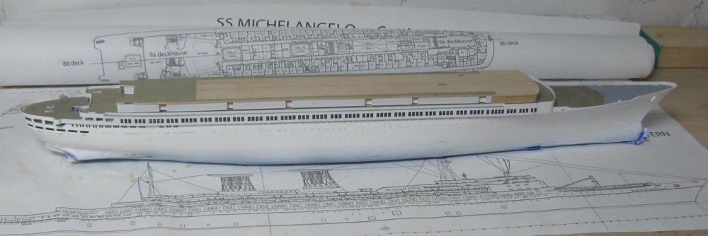
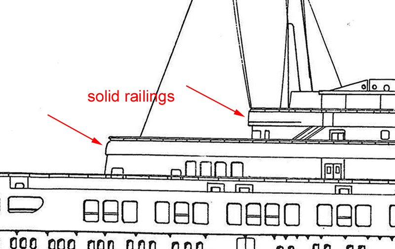
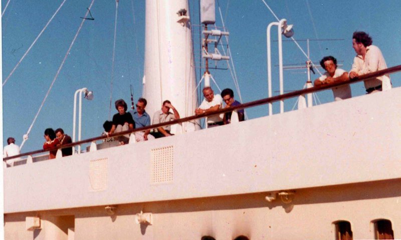
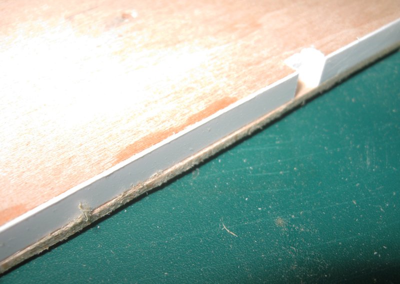
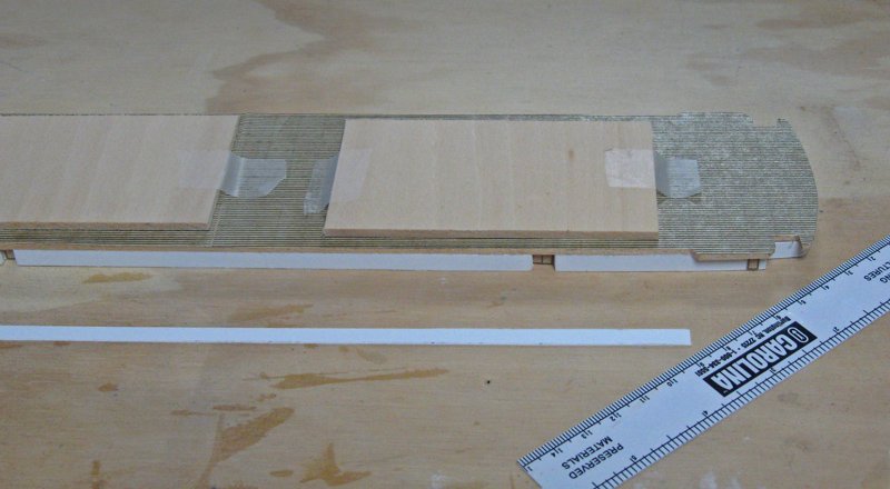
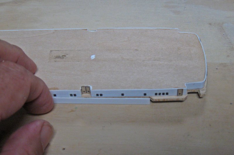
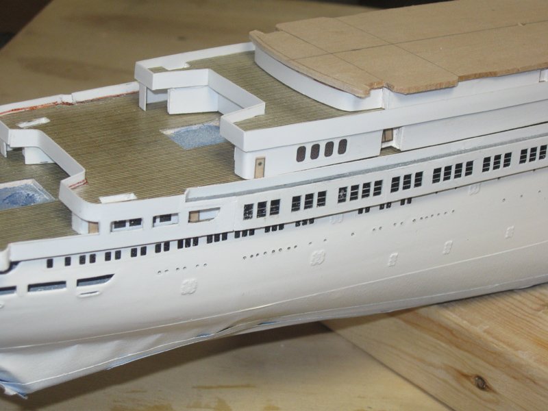
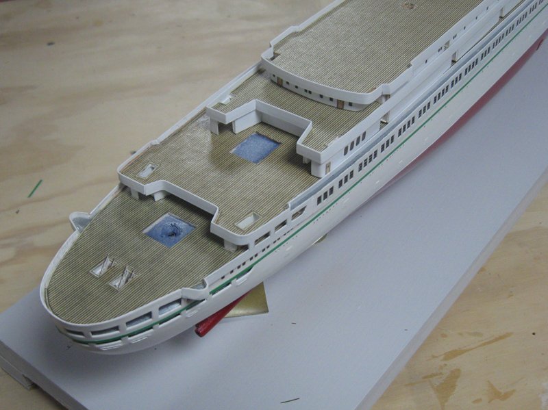
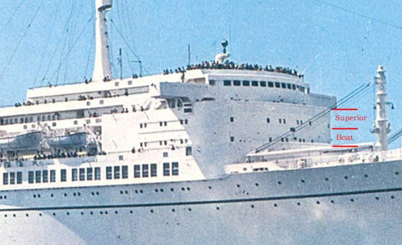
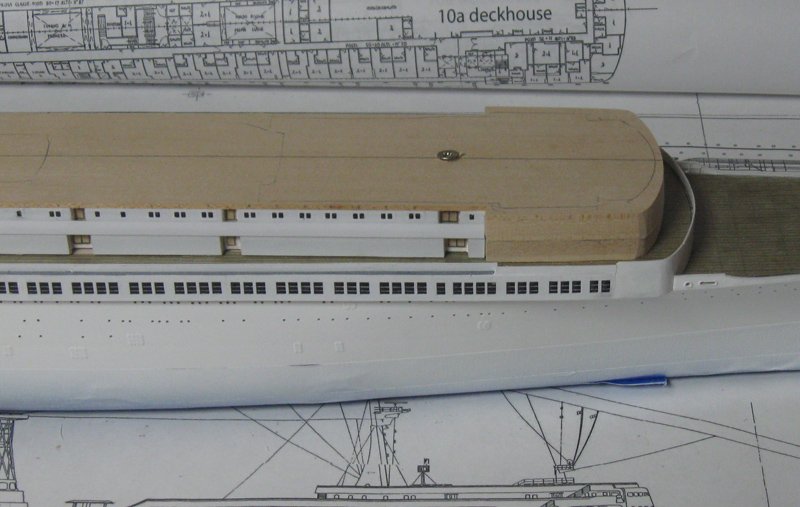
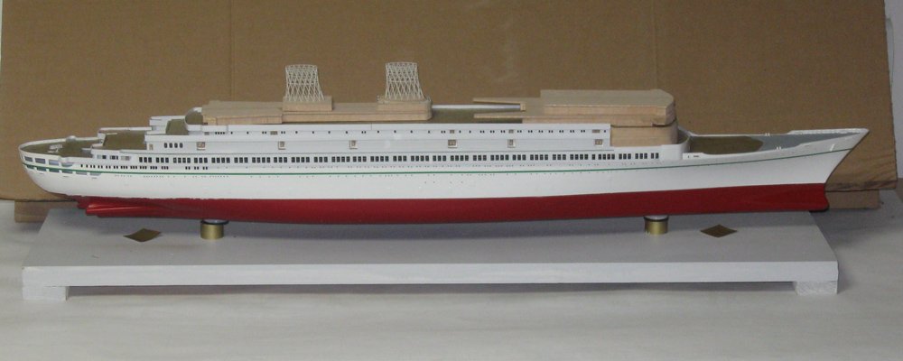
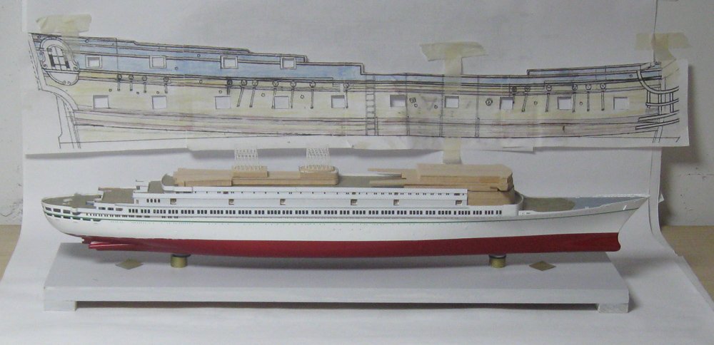
Hi all – Thanks for the likes and compliments, and for following along. Now that the QAR 2 is done and delivered I can get back to this project, and to posting progress reports. Sorry for the long delay. Here is where I had reached last time, the hull shaped and painted, with the Promenade deck done except for some small details. The Boat deck has been shaped, both the deckhouse and its ‘roof’ which becomes the surface of the next deck up, the Superior deck. The Boat deckhouse, including several inset doorways, has been mostly sheathed. Decking sheet has been applied to the Superior deck surface where it will show around the deckhouse. From here the solid railing was applied around the perimeter of the deckhouse. It was important to make sure that it rose a consistent height of 3mm (42”) above the deck surface so it did not look uneven. In addition, this solid railing here and around the Superior deck is shown on the plans and the photographs as overhanging the deckhouse below. The overhang is only about a foot, but it creates a shadow line that had to be replicated. My solution to these two problems was to first shape and sheathe the lower deckhouse. The roof piece was cut slightly overlarge, then trimmed and sanded to sit exactly flush with the sheathed deckhouse. In the photo the deckhouse is upside down with the untrimmed edge of the roof to the left and the finished edge to the right. This is actually the Superior deckhouse and its roof, but the technique for the Boat deck was the same. After finishing the roof edge my paper planking sheets were cut oversize and glued down parallel to the centerline. When the glue was dry the paper was trimmed to the edge. This has to be done now, since it would be much more difficult to cut the decking to fit after the railings are on. On top of the roof several spacers of 3mm sheet wood were loosely taped to the planking Now the deckhouse was turned over again on a clean, level spot on the workbench. A plastic strip 5mm wide was cut, then set down on the bench and offered to the trimmed edge of the deckhouse roof. It covered the edge and, because of the spacers, always rose a consistent 3mm above the deck. Piece by piece it was permanently attached to the roof edge. Here is the railing of the Superior deck overhanging the Boat deck. The shadow line is just enough, I think, to indicate the overhang without being too stark. And here the Superior deckhouse has been capped by the overhanging Lido deck rail. This worked very well for the aft ends of these two decks. At the bow, however, there was a problem. As you can see in the photo, the forward faces of the Boat and Superior decks are flush with each other, as are the sides, aft to a common setback just ahead of the boats. Not only are the two decks flush, but the forward face is sloped aft quite a bit, as seen on the plans. To produce this smooth slope, I needed the two decks fixed together, but to work on the details of the deckhouses, especially the handrails that go above the solid railings, they had to be separate. I have to say that I have not yet solved this problem. I did clamp the decks together, drilled pilot holes and screwed them together without glue. This allowed me to do the rough shaping of the combined bow end, but I found that the positioning was not exactly repeatable, so I am still working on a better solution and leaving the forward area unfinished for now. As a bit of an incentive, I removed the masking from the lower hull and applied the upper, narrow green line with 1/16” vinyl pinstriping tape. I am not happy with the product. It is too thick and does not take the needed curves at the bow and stern very easily. The 3/16” boot topping was impossible to work around the counter at the stern without radical and obvious surgery, so it was removed. Unfortunately, I have not been able to find thin striping tape in green in the right widths. I am still experimenting with other solutions without a lot of success. But with the remaining deck pieces and funnel cages stacked up, I can see that there is a light at the end of the tunnel. And here she is posed in front of the model sized plan for the QAR. Quite a contrast, nu? More soon. Be well, everyone. Dan
- 287 replies
-
- 15
-
-
- michelangelo
- ocean liner
- (and 1 more)
-
Nek0 - Well said, sir. Very well said. I am also on the artistic side of the artist/engineer spectrum of model ship builders. I do not think of myself as building a miniature ship, but creating a sculpture that resembles, to a close degree, the look of a particular ship. The historian in me insists that I get as close to the actual look as I can, but I recognize that this is forever to be out of reach due to the limitations of scale, technique, and my poor talents. It is nice to see that this philosophy is shared by others. Dan
- 2,696 replies
-
- 3
-
-
- heller
- soleil royal
- (and 9 more)
-
Marc - I take it all back. I took a look at what .033 actually looks like, and I am impressed that you got even one centered hole. Great work. Will you be applying them to the hull before or after you paint the planks? Dan
- 2,696 replies
-
- 3
-
-
- heller
- soleil royal
- (and 9 more)
-
Hi Marc - The bolts and washers look good. You are much better at slicing off tiny pieces of rod than I am. I don't know if it is too late for this suggestion, but there is a technique that works for me in situations like this - I drill the holes for the bolt heads before I part off the washers from the styrene strip. A simple jig will give you a line of holes .033" from each other and centered along the strip. Then you just have to cut between the holes. You can drill into the hull where you want the bolt to go, then pin through the washer and into the hull with your bolt. Glue, clip and clean up. Hope that can help you. Dan
- 2,696 replies
-
- 3
-
-
- heller
- soleil royal
- (and 9 more)
-
Roter Löwe 1597 by Ondras71
shipmodel replied to Ondras71's topic in - Build logs for subjects built 1501 - 1750
Hi Ondras - This looks like an interesting project, a build of another 16th Century ship, and quite difficult, with your having to compare and adjust two different sets of plans. I read through your prior build log, and you clearly have all the skills and talents that you will need for a fine rendering of the ship. I have pulled up a chair and look forward to enjoying your progress. Be well Dan