shipmodel
-
Posts
941 -
Joined
-
Last visited
Content Type
Profiles
Forums
Gallery
Events
Everything posted by shipmodel
-
 Hi Sherry - Really nice work. She will be beautiful when fully dressed up. Dan
 -
Hi Michael - I go away for a week and look what progress you have made. Really nice hinges and doors. Dan
-
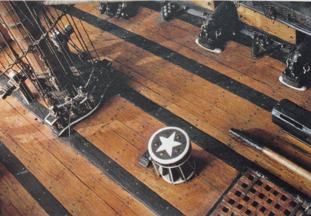
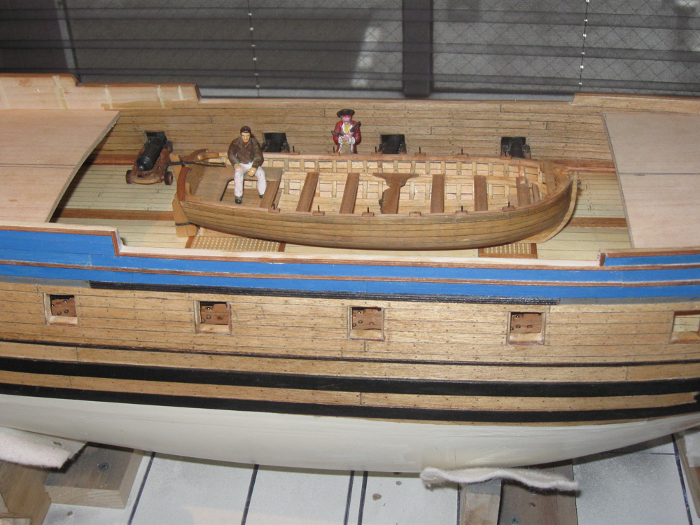
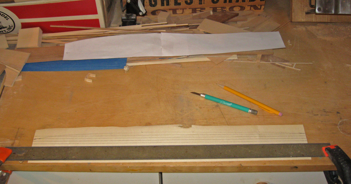
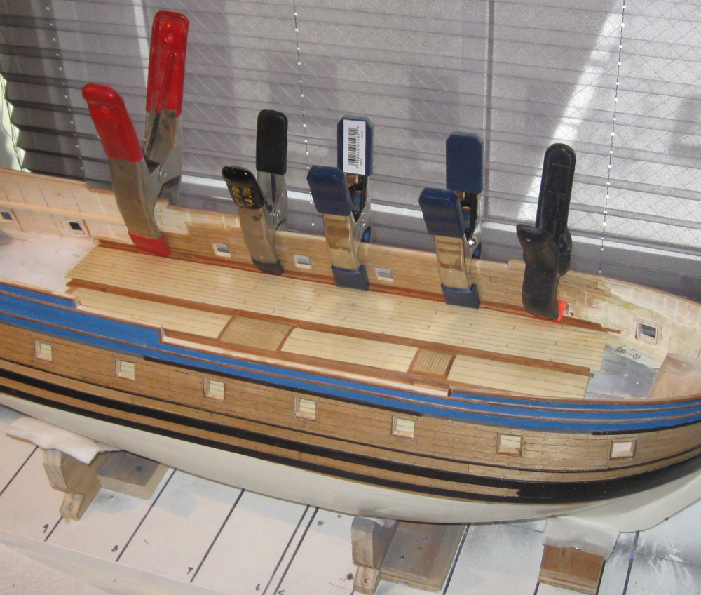
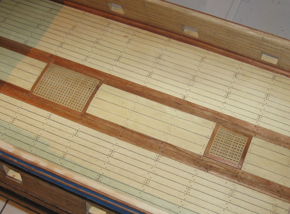
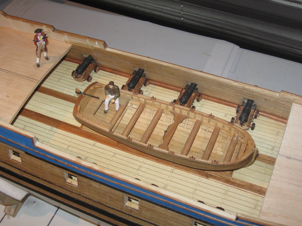
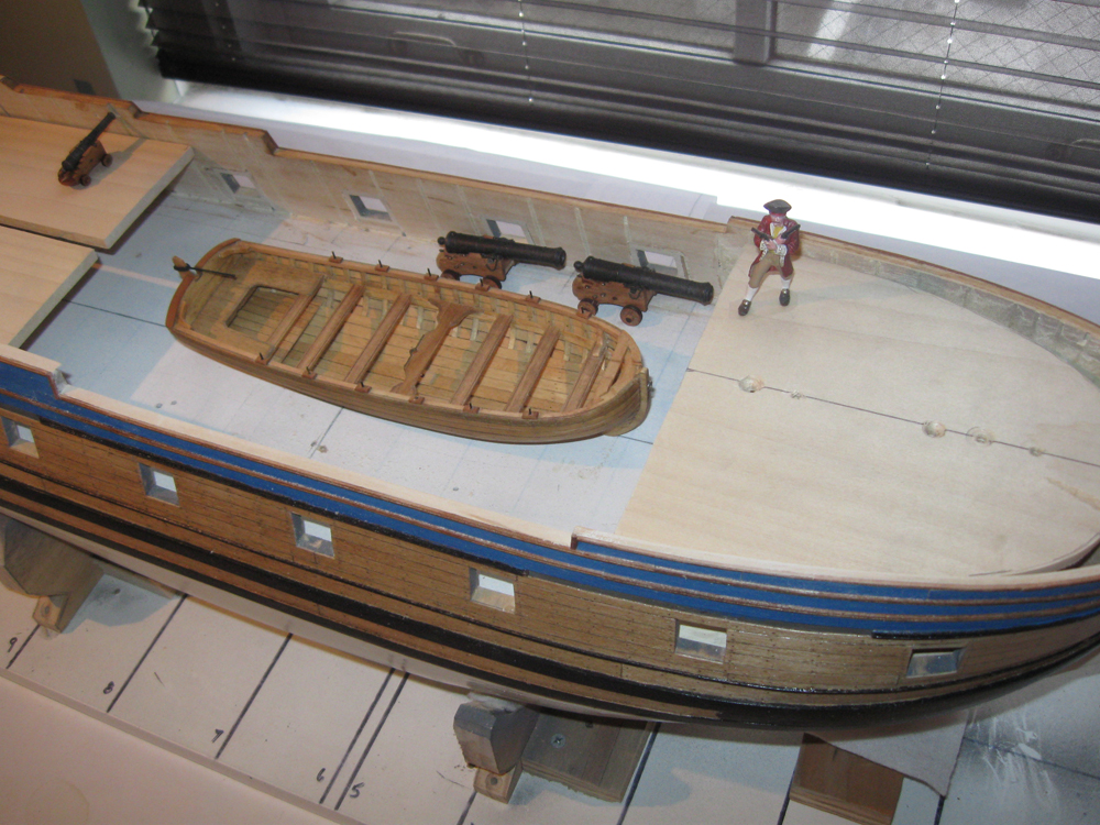
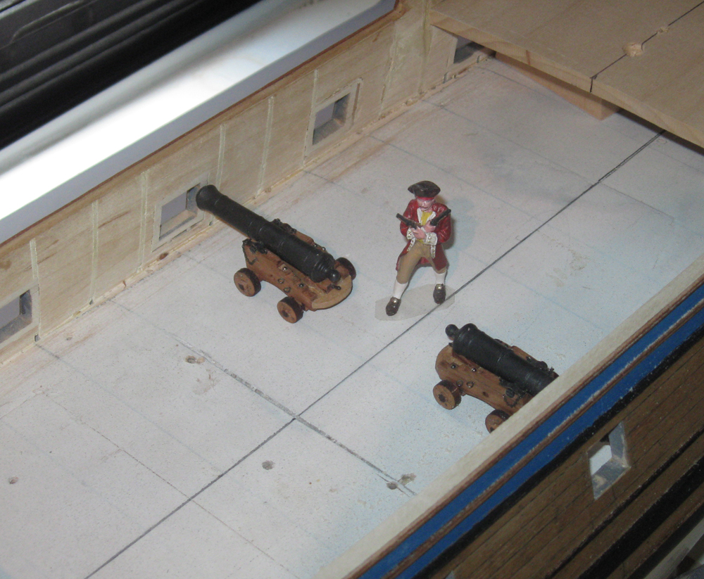
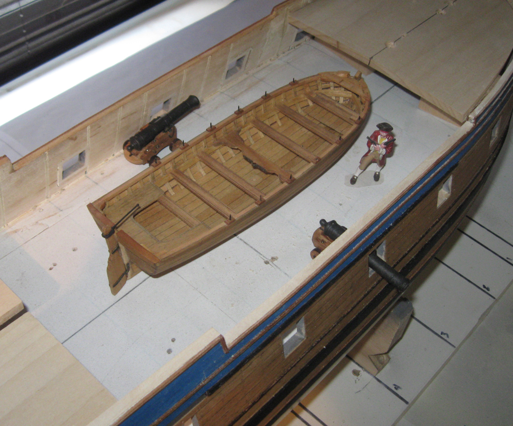
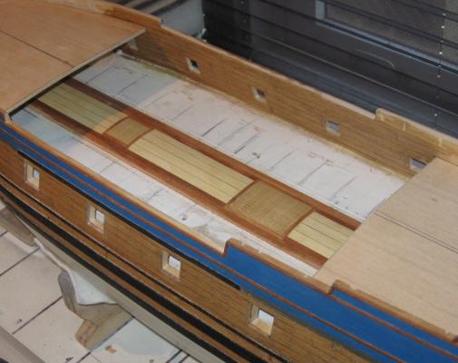
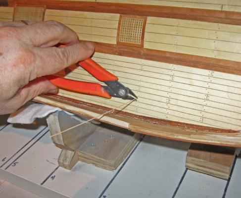
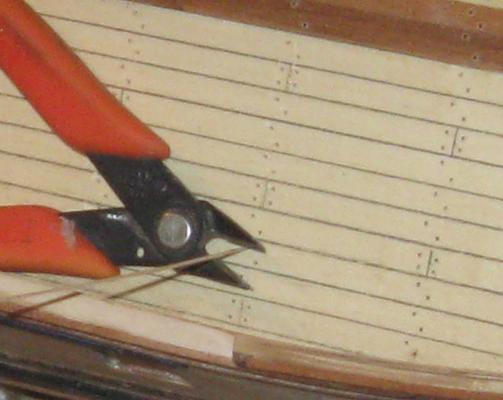
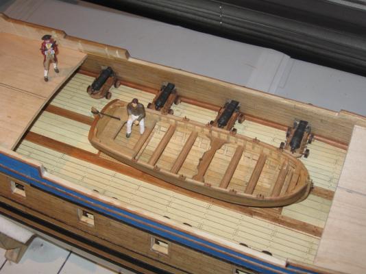
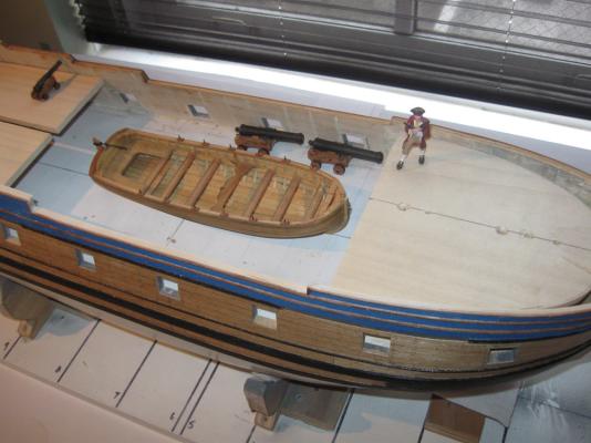
Hi again to everyone following this log. Thanks for all the support, comments and likes. Here is the work that has happened in the last week. I usually put two or more weeks of work into a log entry, but I am going on vacation with the family all of next week, and didn’t want to postpone it. At the end of the last entry I noticed some symmetry problems at the bow. The thin molding was low on the port side, and the starboard bulwark was too high. Here I have corrected the problems. I think that the fix is satisfactory, but I will continue to examine the model to see if there are any others that need work. Next I started on the planking for the gun deck where it will be visible in the waist. The insides of the bulwarks were planked just like the outer surface of the hull, with individual planks of birch veneer glued on with contact cement. Planks were trimmed to cover the gunport frames and linings. Treenail fasteners were done in the usual manner. The planking of the deck in the waist is a little different. Budriot’s plans indicate that the central section of the deck was made up of thicker planks than the rest of the deck. The outermost of these planks were let into the deck beams beneath and are known as binding strakes. They helped lock the deck to the deck beams and strengthened the entire core of the ship. On the model I did not lock them into the structure so they are not binding strakes, but they are made of thicker stuff than the planks. Examination of photos of contemporary French models in the Musee de la Marine (Budriot, Historic Ship Models) indicates a pretty consistent look to this section of the deck. The binding strakes and the gratings are dark, even painted black, while the central planking is lighter and matches the color of the rest of the deck planking. I started with the gratings which I made earlier. These were made on the English pattern, so I crowned them and set them down into the raised strakes so they are nearly flush. These are the first of the early pieces to be permanently attached to the model. The binding strakes are cherry, like the coamings for the gratings, while the central planking is holly. This is a veneer and was glued to crowned sections of basswood to match the curve of the gratings. Once this section was in place and pinned to the deck substrate, I drew the locations for the deck beams, starting with those at each end of the gratings and filling in from there. They laid out with a pretty consistent pattern of 4 scale feet center to center. Now I used the holly veneer to plank outward from the center section. I was going to saw up a bunch of individual planks and do the deck as I had done the outer surface of the hull. But then I decided to try using one large sheet of veneer with the planks marked and scribed on. After a satisfactory test piece was made I decided to go for it. A paper pattern was made that fit the area from the binding strake to the base of the bulwark. This was laid out onto a piece of holly veneer, but not cut. Using a long metal ruler as a straightedge a series of 6mm wide planks were laid out on the wood. With the veneer clamped under the ruler a pencil line was drawn with a 0.5mm mechanical pencil so all the lines would be a consistent width. Without unclamping I scribed the line into the wood with two light passes using the back of a #10 blade. The markings were made permanent with two coats of spray satin finish. With the planks lined out I cut and trimmed the veneer piece until it fit snugly into the space from binding strake to bulwark. I test fit the piece in place and lightly marked the beam locations onto the veneer. Using the straightedge and a small square the butt joints were marked out, penciled and scribed as before. I used a 3-step pattern with a 1-3-2-4 stagger. I don’t know if this is historically correct for French ships of the period, but it looks right. After a final sanding to smooth the deck substrate several coats of thinned contact cement were painted onto the deck and the veneer piece. When dry the piece was laid in place and burnished down to the substrate. This is a permanent bond, like a kitchen counter, but the treenails that will be installed doubly guarantee adhesion. At the base of the bulwarks a margin plank, finish plank, and chamfered waterway were installed. They are cherry and contrast nicely with the birch of the bulwark and the holly of the deck. Now all the fastening holes could be drilled. Careening the model in the cradles gave me access without straining. As with the hull planks, I used square treenail sticks pressed into round holes and clipped short, leaving just nubs of wood above the surface of the planks. When all the holes were filled they were painted with dilute white glue. When the glue dried the nubs were cut off flush with a small sharp chisel. The fastenings are birch which subtly contrasts with the holly without becoming overbearing. The fastenings in the cherry binding strakes were made of walnut, also for a bit of contrast. With the waist planked it will soon be time to work on the upper decks. Here I have laid up the substrates for the three sections. They are made up of two layers of 1/16” basswood glued over a curved form. The laminated pieces held their shapes quite well after the glue dried. Paper patterns were used to get the right outlines. The pieces were cut on the band saw and refined with a bench disc sander. With the deck pieces temporarily installed I fitted out the waist with cannon, the ship’s boat, and my figures. I don’t see anything when I examine the model or in the photos that looks obviously wrong, but my eyes are getting old and I am a bit biased. If anyone sees anything, please tell me now while I can still get at it to change it. Thanks Dan


- 241 replies
-
- 17
-

-
- queen annes revenge
- pirate
- (and 2 more)
-
David - sure thing. Best wishes for a speedy and complete recovery. Dan
-
HI all. Thanks for the comments and likes - Hexnut - I plan to bring her to New London, if there is room in the car. I am giving a lift to some of the other NY club members, so it may not be possible, but I will do my best. Michael - I think of my modeling as a pointillist painting. All of the really small details, like the fasteners, may not be visible individually in the finished model but overall the effect gives it a 'texture' that it would not have without it. David - At the end of a long treenailing session I relax with two fingers of Maker's Mark on the rocks - repeated as often as needed. Sorry that Manitowoc is beyond my range for such a large model. I have no idea how Ozzie Thalman schleps his Bismark or Arizona out there. More power to him. I can't wait to see Micheal bring his Bristol cutter to a show :-)) Be well Dan
- 241 replies
-
- 1
-
-
- queen annes revenge
- pirate
- (and 2 more)
-
ROYAL CAROLINE 1749 by Doris - 1:40 - CARD
shipmodel replied to DORIS's topic in - Build logs for subjects built 1501 - 1750
Really wonderful, Doris. I' ve never seen a model with as much 'life' as yours. Thanks so much for sharing. Dan- 883 replies
-
- 1
-
-
- royal caroline
- ship of the line
- (and 1 more)
-
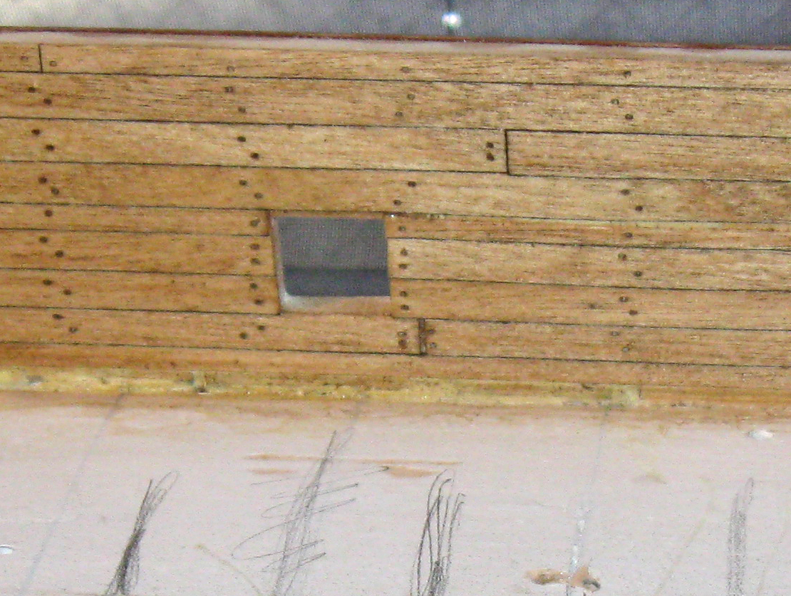
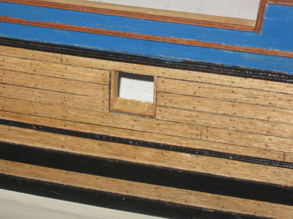
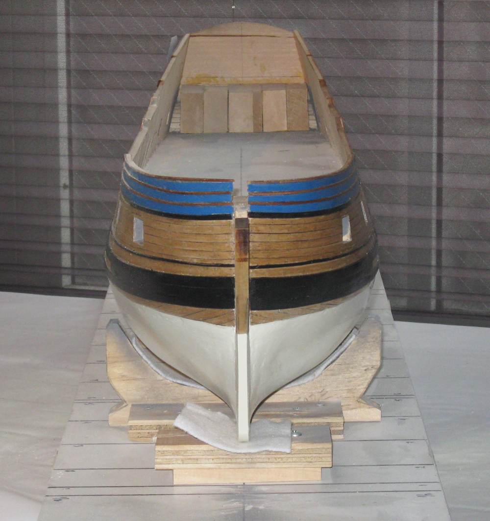
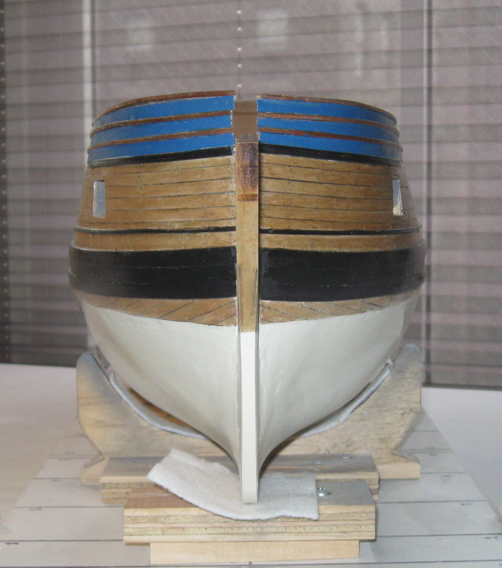
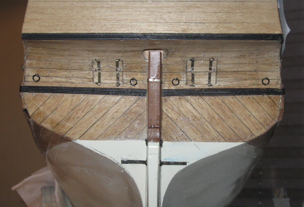
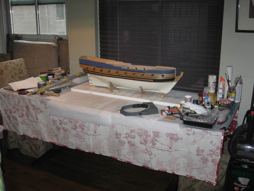
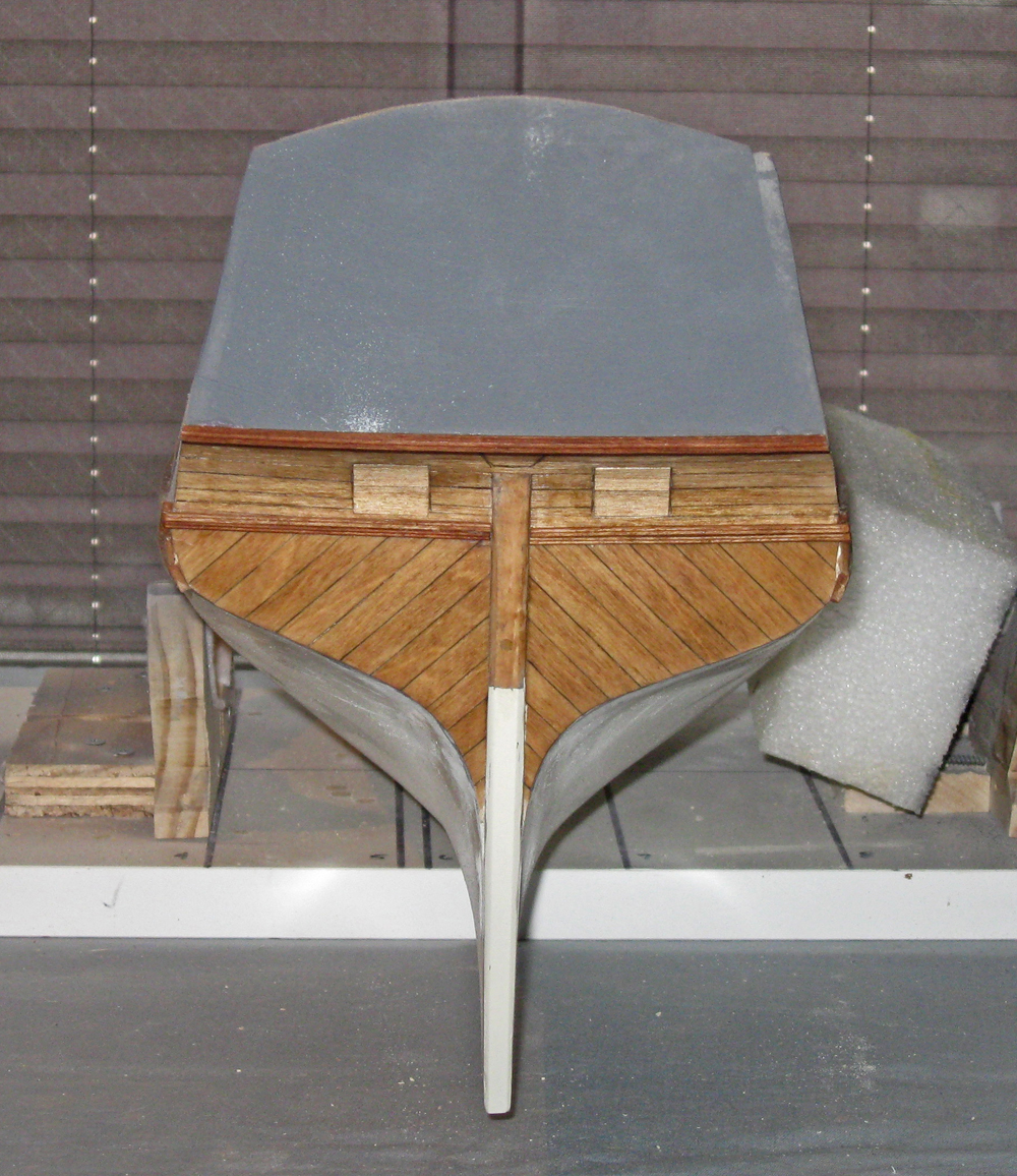
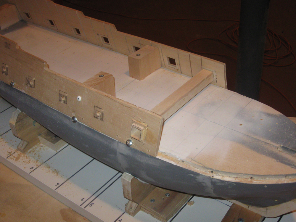
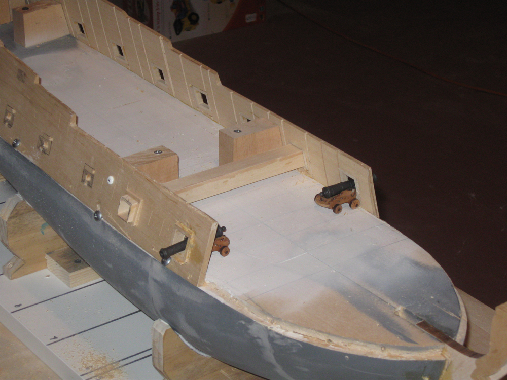
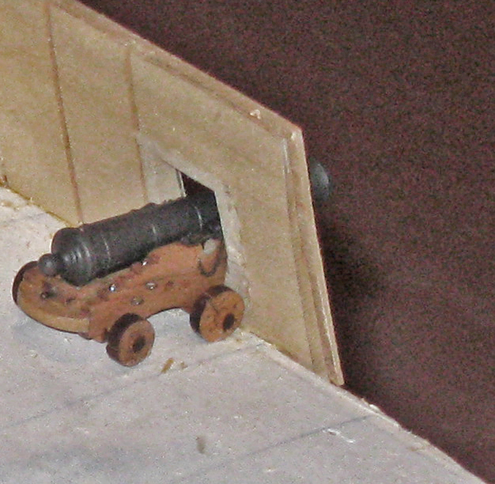
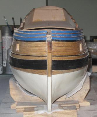
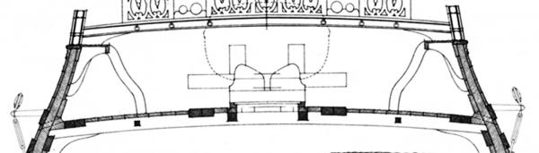
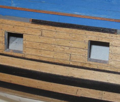
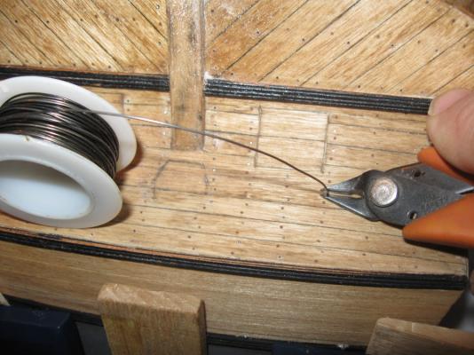
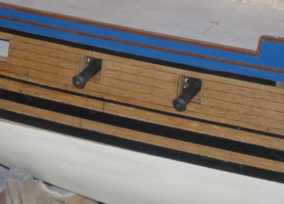
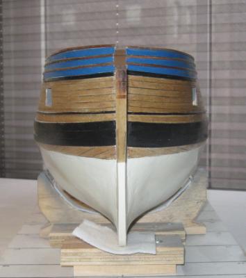
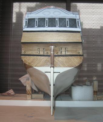
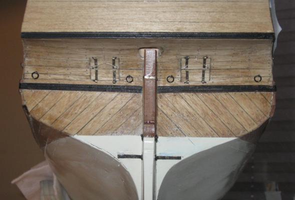
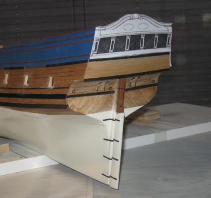
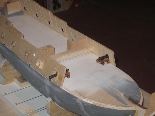
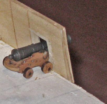
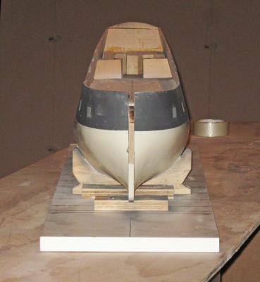
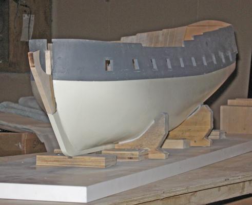
Hi to all, and thanks for the comments and questions. Please keep them coming. Many eyes and brains will always spot problems that one set will not see until it is too late to easily correct them. The last entry ended with the hull planked and the upper works painted as requested by the museum. The next task was to install all of the plank fastenings. French practice at the time, as far as can be determined 300 years later, was to alternate wooden treenails with iron spikes. That is, each time a plank crossed a frame there were two fasteners, one iron, one wood, set at a diagonal to each other. At the neighboring frames to either side the pattern was flipped over, so if the first frame had a treenail at the top, the neighbor had a spike at the top. Butt joints between planks were secured with four fasteners, two of each kind, also set diagonally. Here is what the finished pattern looks like on the model. The experiments that I did on the practice gun station led me to the following sequence, which got the thousands of fasteners done in a reasonable amount of time: After installation, the planks were given a coat of pale stain, then a first clear coat to protect them from glue spots and dirt. This coating also helped when it came time to remove the pencil lines that were drawn to indicate the frame locations under the planks. Without it the graphite gets into the grain of the wood and is really hard to remove. Next, the holes for all of the treenails were drilled. I used the cordless Dremel 1000 which has a pistol shape. It lets me simply point at the desired spot and just lean forward to make a 1/8” deep hole. With some good music in the background and a repetitive chant under my breath, I would develop a rhythm that made the chore go pretty quickly. Multiple strips of treenail stock were cut from cherry veneer on the Preac. They were 0.025” square, or about 0.035” on the diagonal. The holes were drilled with a 0.0325” bit so that the strips could be inserted to the bottom of the hole with a friction fit and then clipped or snapped off. Again, music made the task bearable. Once all the holes were filled they were painted with heavily diluted white glue. It was thin enough to wick down the sides of the strips to the bottom of the holes. This not only secured the treenails to the planks and the hull, but it swelled the fibers so that the square strips now filled the entire round holes. No lengthy, fiddly pulling through a drawplate was necessary. This is a good thing, because I am really terrible at it. I usually end up with more splinters on the floor than treenails in the cup. Once the glue dried the stubs of the treenails were cut close to the plank surface using a small chisel, then they were sanded flush, which also removed the pencil lines. Now the holes for the spikes could all be drilled, using the treenail locations as the guide. This time the holes were only 0.025” diameter and were filled with 0.022” soft iron wire. Clippers were used to cut them as close as possible to the plank surface. Here I am filling the holes in the planks of the counter with the model turned upside down. Once a large section of spikes were inserted they were peened or pressed into the hull until they were almost flush with the surface. Then they were painted with a second clear coat of finish. This not only secured the spikes from coming out, but darkened the tops of the treenails so the cherry stood out from the birch of the planking. Even without doing the fasteners under the painted sections there are over 3,000 fasteners in the hull. Using this sequence, the fasteners were done, start to finish, in three 6-hour workdays. With the planking done, the gunport linings were fitted using the square wooden tube as explained in the earlier log for the gun station. Here is how it came out after staining to match the planking. And here are two cannon protruding from their ports as they will be in the finished model. As we all do, I use the photographs to check my work. Some things seem to appear only under the light of a flash. Here I am checking the symmetry of the bow. It looks generally good, but there are two problems that I have to correct. First, the thin molding just above the wale does not match, port to starboard. The port side is about 1/16” low at the stem. It will be pried up and relocated before re-gluing and final pinning with metal spikes. The second problem is less clear. The cap of the starboard bow is higher than its corresponding shape on the port side. You can see it a bit better with the photo taken from a lower angle. The cap molding will be removed, the shape adjusted, and the molding replaced. Otherwise, I am happy with the symmetry of the hull both here at the bow, and here at the stern. You can see that the two ports in the counter have been detailed. Although the hull details will mostly be done later, it was easier to do this area while I could still turn the model over and work on it upside down. The ports have two half-lids with four hinge straps each and a lanyard to open the top half. These were made in the same way as the hinge straps for the companionway that was shown in an earlier log. I used my orthodontic pliers to bend 1/16” brass strips which were then drilled and chemically blackened before gluing and pinning with wire. The four rings above the lower molding are for the preventer chains that will attach to the smaller rings on the sides of the rudder just above the white stuff. The rudder itself is built up from two pieces of cherry which were cut, shaped and tapered according to the plans. The gudgeons and pintles were bent up from 3/32” wide brass strips, blackened and drilled, then secured in the usual manner to the rudder and the hull. At the transom you can see the paper pattern for the latest iteration of the stern gallery of windows. This was originally taken from the Mercure plans, but heavily modified to fit the internal deck layout of the Advice Prize. It was pushed, prodded, resized, and details were changed and changed back again in Photoshop before being printed out to test size and suitability against the spacing and layout of the hull moldings. More changes will be made, I’m sure, before I am completely happy with it and can start cutting wood. I’m having to do a lot of testing like this to reconcile the shape and layout of the Advice Prize with the details from Le Mercure. Here I have installed rough place-holders for the quarterdeck and forecastle deck so I can plan the layout in the waist. The museum asked that one broadside of cannon be mounted through the ports with the lids opened. The other side will have the guns “housed”. But when I tested the layout of the guns with their muzzles hard against the bulwark it was clear that there would be no room for the ship’s boat on the centerline. A check against the plans confirmed that this was so. Instead, I suggested that the cannon not in use be housed fore and aft against the bulwark. This is one way that it was done on the real ships. Now, with the opposite cannon through the port, there is enough clearance for the boat and to work the guns. And here is what the broadside looks like before the gunport lids and the rest of the hull details are installed. Finally, lest you think that I work in a clean and orderly manner as implied in the heavily cropped photos in the log, here is our dining room table on a fairly neat day. It looks much worse on a daily basis and for months at a time. I can’t say enough about the forbearance and good humor of my wife. Without her this would not be remotely possible. I can only wish you all the same happiness with your spouse or significant other. Be well Dan


- 241 replies
-
- 21
-
-
- queen annes revenge
- pirate
- (and 2 more)
-
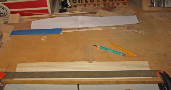
Hi David - Although both ways can get the job done, I have to disagree a bit with your take on safety. Kickback is caused by the workpiece being trapped and squeezed between the blade and fence. When it catches the spinning blade throws it back at the worker. The way Mark has his saw set up, the larger piece of wood is in this position. If it kicks back it could cause some damage. If the small piece kicks back, a strip 1/32" x 1/8" can't do a lot of harm. As for pinkies, that's what push sticks are for. I use them all the time. Dan
-
Hi Mark - Nice work on the boat. The keel looks right. Once you get the garboard and sheer strakes planked it will really take shape. I am a bit confused about the sawing method. It seems as if you are using the featherboard as the fence and the fence as your featherboard. I would think that the inherent flexibility of the featherboard fingers will give you uneven plank thicknesses, depending on how firmly you push the wood against them before you set the fence for each cut. If you have an accurate mini table saw (it looks like you have a Byrnes saw) you should have no trouble setting the fence to a 1/32" distance from the blade and then ripping off multiple identical planks without moving any part of the setup. Just another way to get the job done. If your method works for you, go with it. Following with interest, as always. Dan
-
Hi Sherry - I was taught that quarter badges are the small "bay window" looking bulges on the aft hulls of small ships. On ships of the line like yours, the large constructions that rise several decks are known as quarter galleries since they were connected to the galleries at the stern. In either case their purpose is to house the officers' washstand and other conveniences. The piece at the bottom that you have carved so excellently is called the drop, possibly because this is where the waste from the toilet dropped into the sea. Keep up the good work, I truly enjoy watching your progress and am glad to be a tiny bit of your inspiration. Dan
-
Hi Sherry - Just found your build log and got a little time to look it over. Wonderful work-woman-ship. It's just a shame that there are only so many hours in the day and days in the year to study, appreciate, and learn from talented builders like you. Whenever I can I will go back and read all the pages from the beginning, and all the future pages as well . It sure beats watching reruns of CSI . . . Be well Dan
-
ROYAL CAROLINE 1749 by Doris - 1:40 - CARD
shipmodel replied to DORIS's topic in - Build logs for subjects built 1501 - 1750
Doris - You are really bringing your work to life with your figures. Bravo . . . I echo everyone else's respect for your work. Please can you tell me where you found the hooks for your train tackle? They are just what I am looking for. Thanks. Dan- 883 replies
-
- 1
-
-
- royal caroline
- ship of the line
- (and 1 more)
-
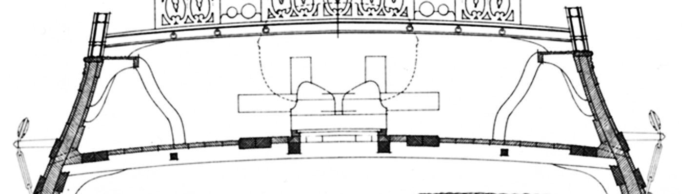
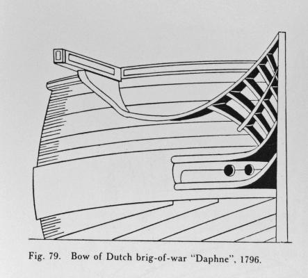
Hi Mark - I have not made any specific study of the development of the hook scarf planking feature. If the French took their cues from the Dutch, it lasted quite long, and possibly through the entire Era of Sail. Petrejus shows it in his book on the brig "Irene", launched in 1807, about 100 years after the QAR, and has references to other Dutch ships from the late 18th century. Here are two illustrations from the book Frolich also shows this kind of planking on some of his models. However, there are a number of inconsistencies in his spiling work that keep me from relying on him as the final word on the subject. Hope that helps. Looking forward to watching the Licorne take shape. Dan

- 241 replies
-
- 4
-
-
- queen annes revenge
- pirate
- (and 2 more)
-
Hi David, Michael. Thanks for the compliments. Why birch or why veneer? I used veneer because once I knew that the hull was going to be solid, it seemed the easiest way to render the appearance of planking without the work of cutting, bending and fitting thicker stuff. The actual thickness of the planks is almost never exposed, just as the thickness of the paint on a painting is unimportant. In this scale veneer is thick enough to allow a little sanding without going through it to the substrate. I just had to make sure that the shape of the hull was smooth and fair before the planks were applied. I used birch because it was the best choice among the available veneers, which mostly run to exotic figured woods for the furniture market. Once it was stained it took on a warm tan color that closely matches an aged pine planking, which the original ship would have used. I am using cherry veneer for some of the decorative moldings, and the decks will be holly veneer. Michael, the contact cement is Weldwood’s original polychlorprene formula in the red can. I experimented with the water based formula, but did not like it as much. Here is the link to the Minnesota Historical Society study. http://www.mnhs.org/preserve/conservation/reports/exhibits_handbook.pdf Hope this answers your questions. Dan
- 241 replies
-
- 2
-
-
- queen annes revenge
- pirate
- (and 2 more)
-
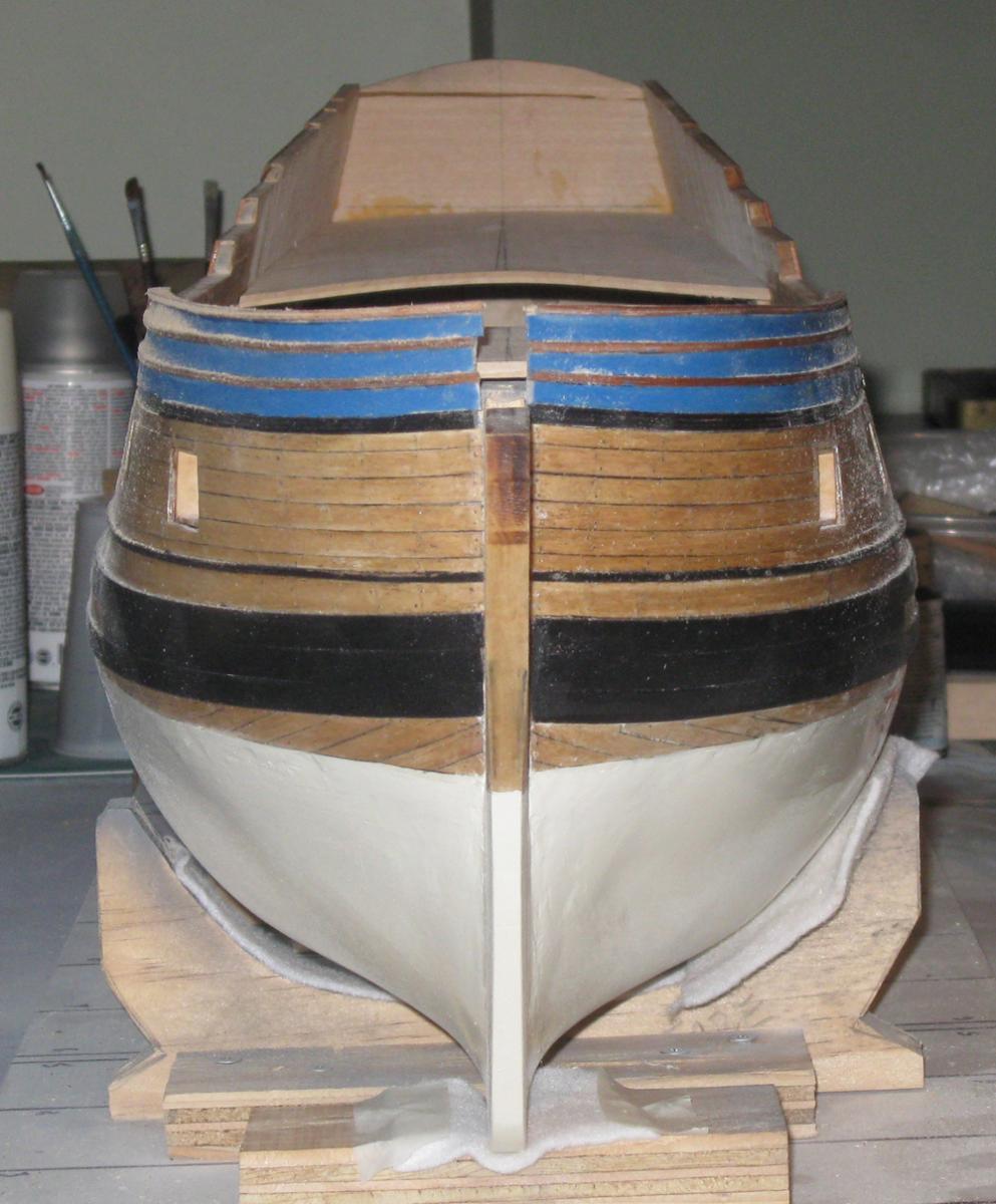
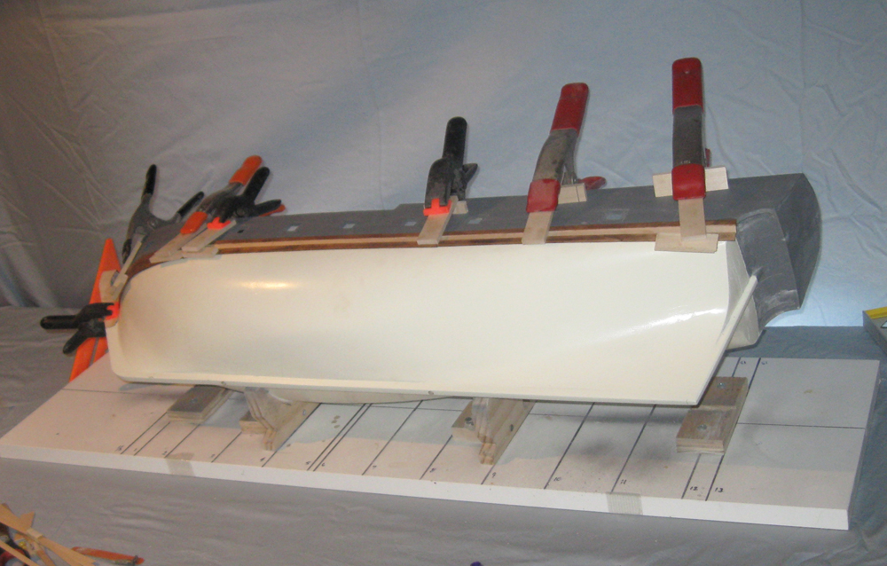
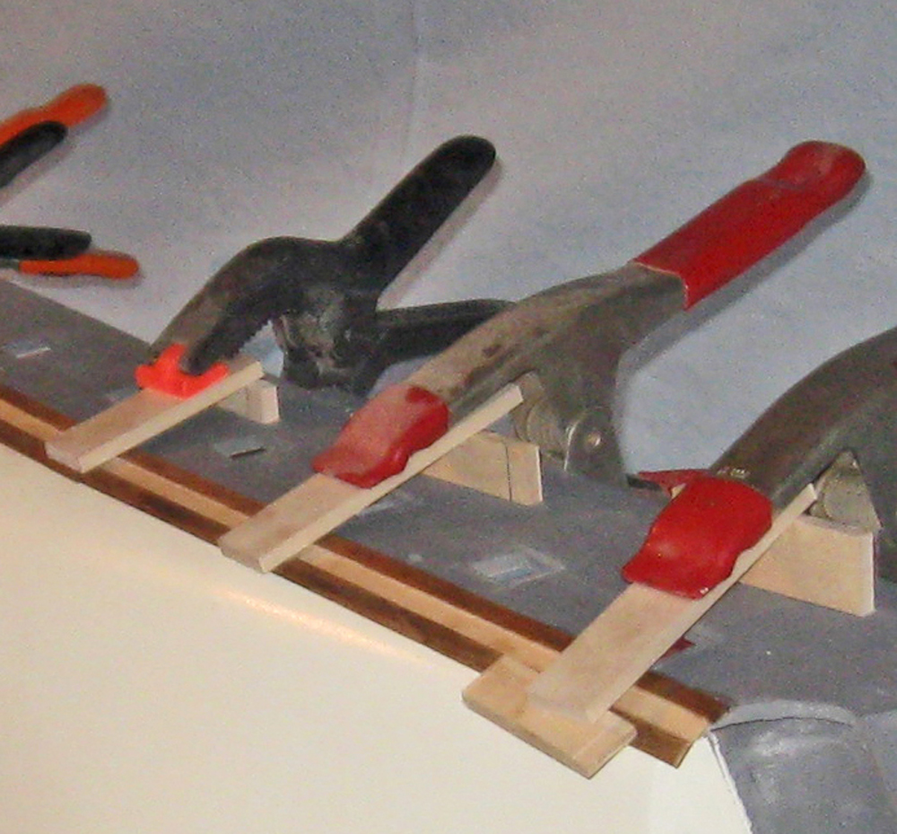
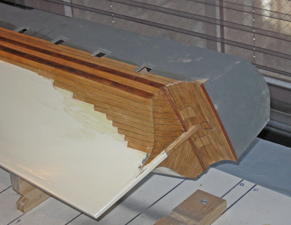
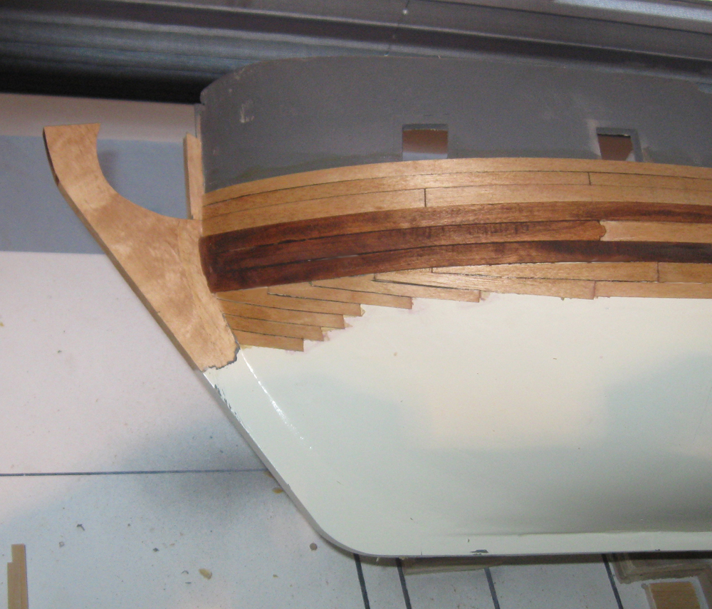
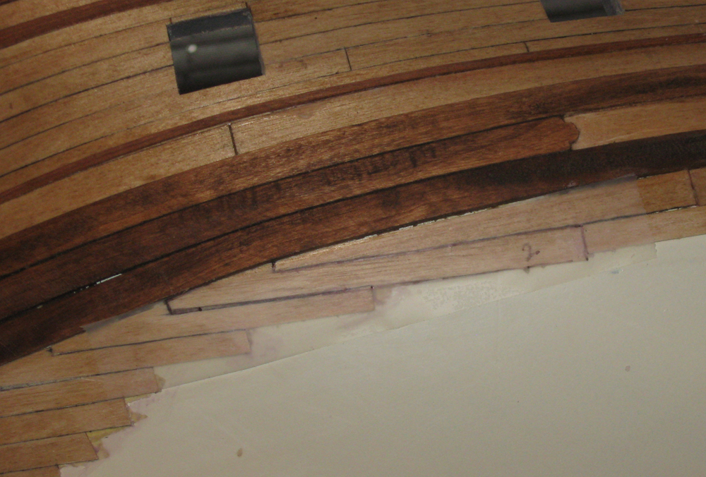
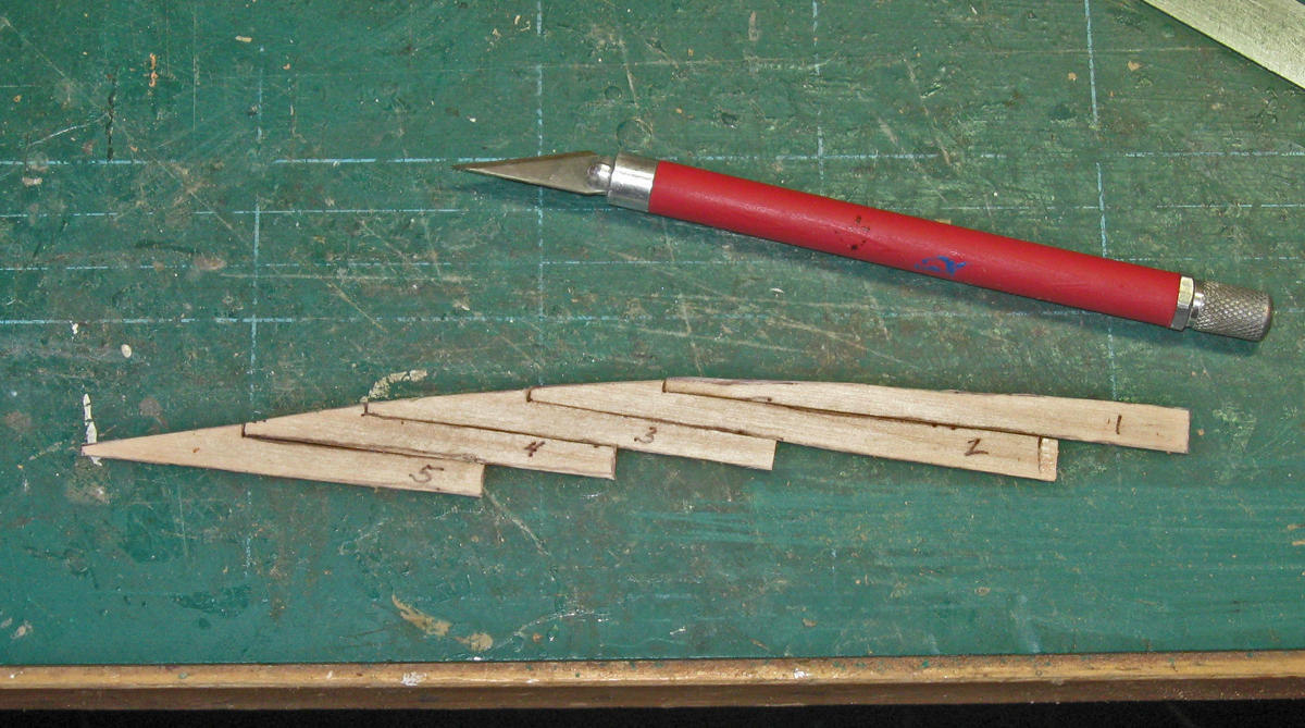
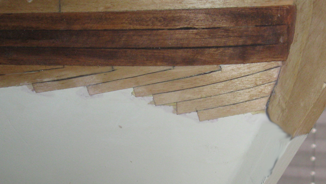
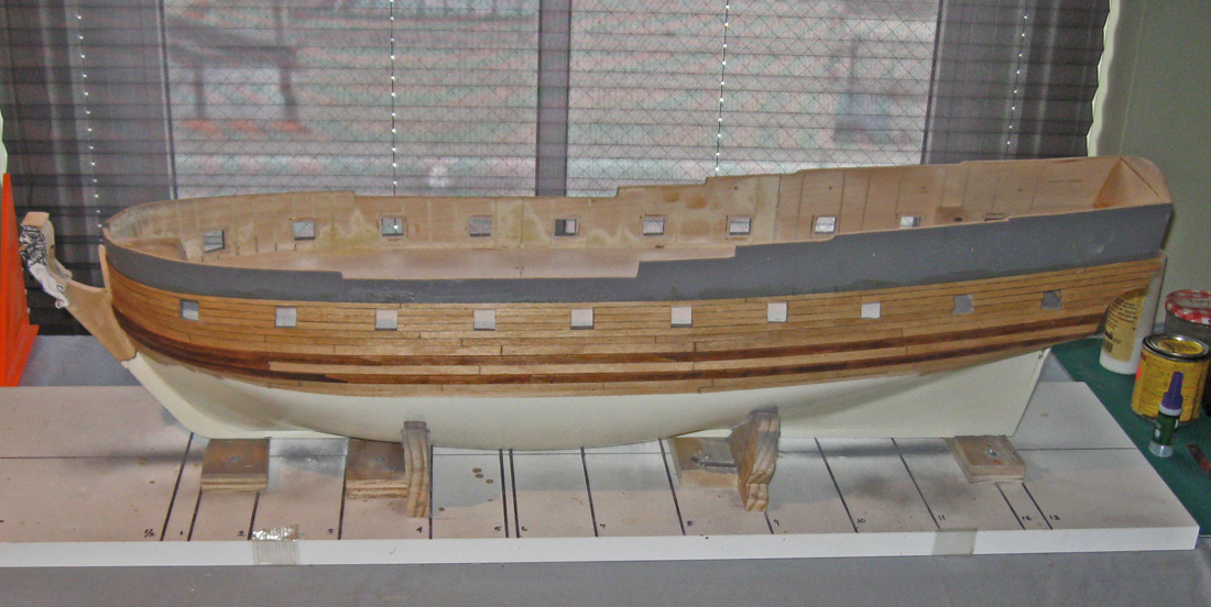
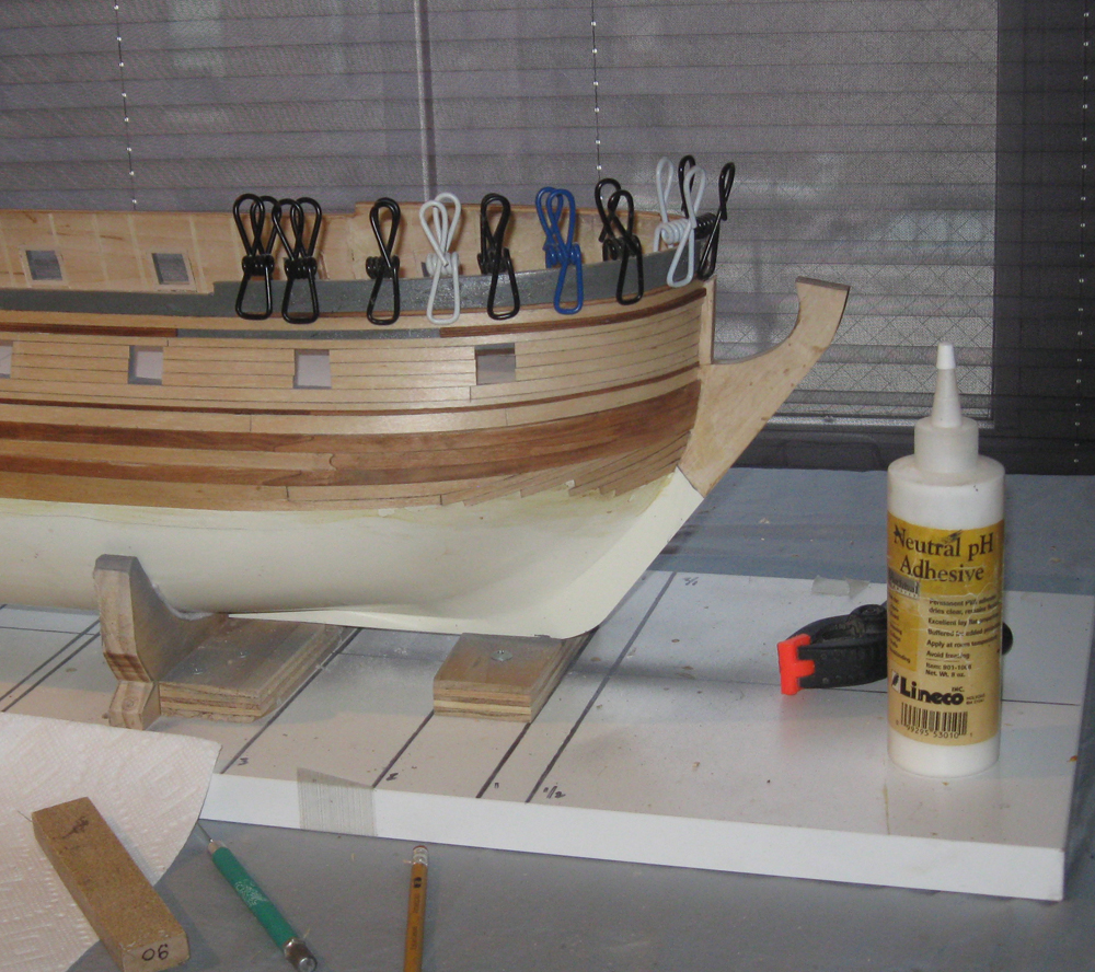
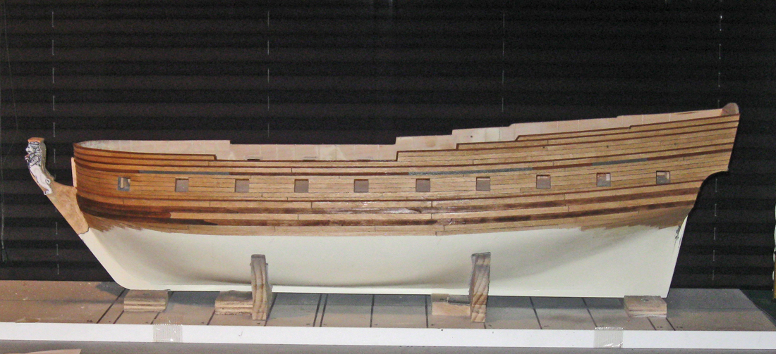
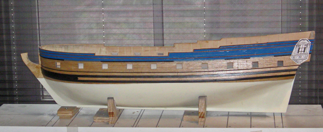
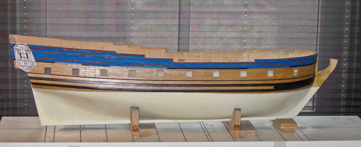
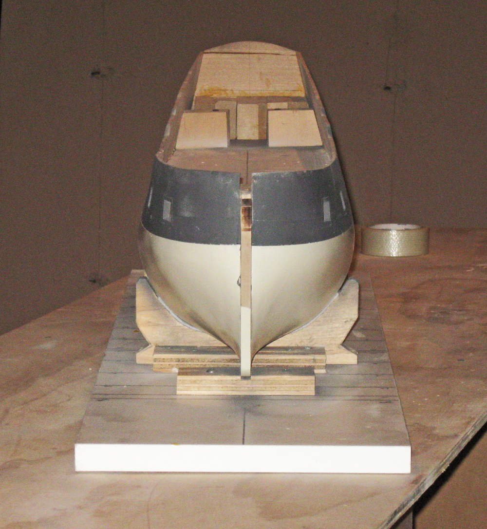
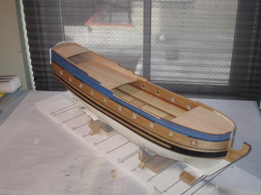
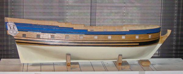
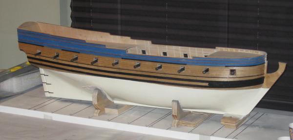
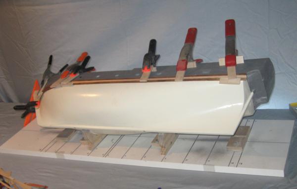
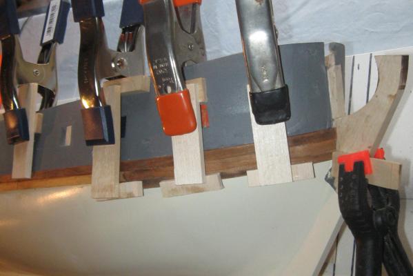
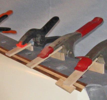
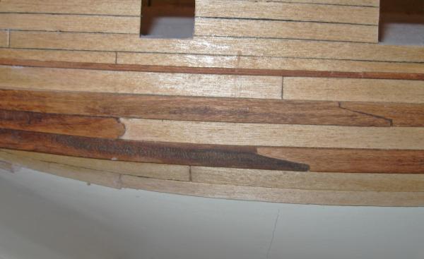
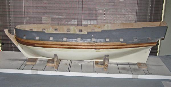
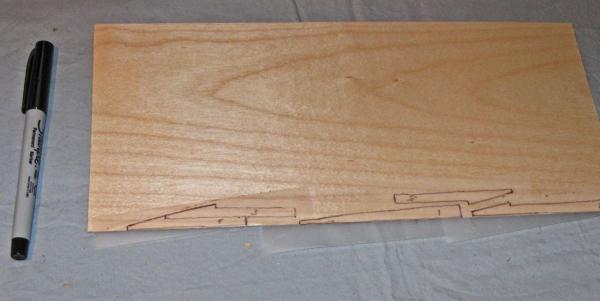
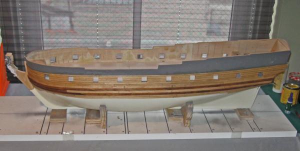
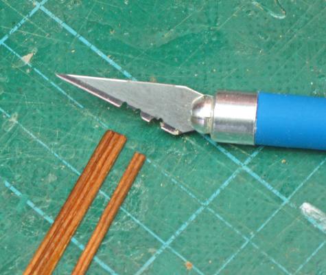
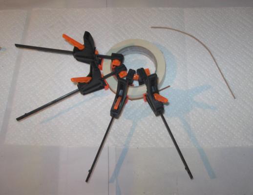
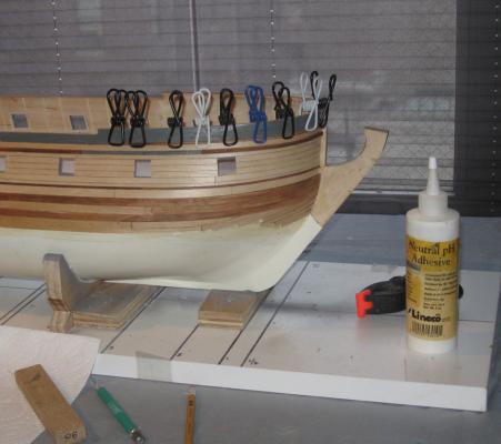
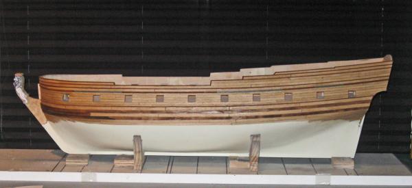
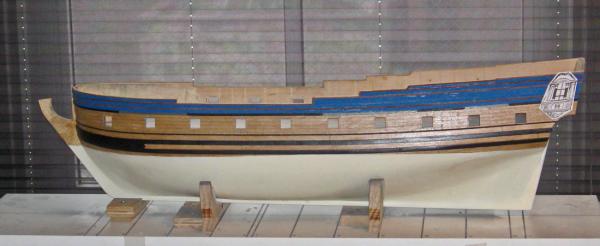
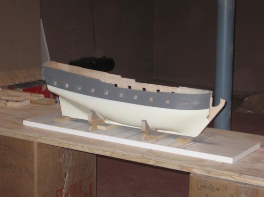
Hi to everyone who is following this log, and thanks for your interest. Druxey - I believe in catch and release. She will come back, I'm sure. Now that the hull structure was fully shaped, smoothed and primed, I turned to the main wales. French practice, as derived from some of the contemporary models, was to have two strakes of dark, heavy planks run the length of the ship, separated by a strake of slightly thinner planking that was not as dark. I selected cherry for the outer strakes and birch for the inner one, to match the woods used on the rest of the model. The upper cherry strake was laid in sections along the line of the hull paint and glued down. It will be pinned for security later. A good deal of care was taken with this first strake as every following strake takes its curve from this one. Once I was happy with the first wale strake, the middle strake of birch was laid against it, then the lower strake of cherry. Because of the curvature of the hull, the edges of the planks all had to be undercut so they could lay tightly against each other. The curvature of the hull also made clamping difficult. The lower strake is substantially under the curve, especially at the bow and stern. Since the bulwarks do not go down to the level of the wales, I could not get any direct clamping access. I came up with a system of cantilevered scraps of wood to do the job. Here at the bow the problem was not that acute, and you can see how the force from the spring clamp is exerted between the upper fulcrum and the load at the lower edge, even though it is around the curve. It’s crude, but it worked. At the stern the more extreme curve required raising the fulcrum and, at the aft end, even adding an angled caul to hold down the wood. Each section of the wale was joined to its neighbor with a long scarf joint. These were all marked out with a pattern cut into a plastic strip so they were consistent, cut on the band saw, and cleaned up by hand. The forward end of the middle strake was as thick as the outer strakes, probably to reduce the chance of the anchor fluke catching an edge, much like the billboard did in later ships. It was finished off with a decorative scallop, a detail again taken from another contemporary model. Now that the wales had been set, the planking began. I used birch veneer with a thickness of 0.025” – about ¾” in scale. This had some good attributes, but required some new techniques. Doing it this way owes more to the art of marquetry than the engineering of a ship. The thinness of the planks means that they can be cut easily from a veneer sheet with the Preac using a fine toothed blade, and even shaped with scissors. But they are somewhat delicate until they are glued to the hull. They are also quite prone to warping if they come in contact with any moisture, including water based glues. So to secure the planks I used contact cement. I had used it before for the copper plates on models of later ships, but never on wood. First I had to clear its use with the museum. I found a study online from the Minnesota Historical Society which approved its use in conservation applications, so I was given the go-ahead. I thinned the glue with mineral spirits and painted a coat onto the hull and the backs of the planks. When it was dry I colored the edges of the planks with an indelible marker. The hull got a second coat of glue. You can see it as the shiny area above the planking on the primed hull and the yellowish area below the wales. When this second coat was almost dry, the plank was seated in place. This gave me just a little wiggle room to adjust the fit of the plank yet still gave lots of adhesion. Once the concept had been proved out, I planked the stern and counter so that the hull planks could run past their ends before being trimmed to fit. Below the wales the planking was carried down about an inch below the final location of the waterline. The ends of the planks will be feathered into the solid hull and covered by the “white stuff” of the lower hull. At the bow the planks do not all run into the stem, as in English practice. Following the lead of Budriot, Petrejuus, and Frolich, the last five planks have hook scarfs and run up to the lower edge of the lower wale. Once these shapes had been resolved for the port side by trial and lots of error, I transferred the shapes to the starboard side. A piece of translucent tape was laid over the planks and the outline of each plank was drawn on it. Here I am doing plank #2. Once the shape was drawn, the tape was removed and laid on a sheet of veneer. This was done for all five planks. It did not matter that the tape overlapped since all the tape would ultimately be removed. I packed them against each other so there would be little wasted wood. They were cut out with a new blade in the knife and fit together quite well. With a little fine tuning they laid quite well against the starboard hull and match the lines of the port side planks. The planks were continued up the hull, cutting out the openings for the gunports as I went. Just above the gunports is the line for the channel wale. This is a wide and thick molding made from 1/16” thick cherry. There also needs to be a lot of thinner decorative molding. The moldings were made in the usual way. I ground the profiles into a used hobby blade with a thin cutoff wheel in the Dremel. Others use old hacksaw blades for this, but I have a lot of old knife blades and it lets me use a handle, which is easier to hold and helps with my trigger finger issues. After the profile was scraped into the stock the pieces were stained and set aside. At the bow there is a significant curvature, so the sections of the moldings were soaked in hot water for about an hour then clamped to a handy form – a roll of masking tape. When dry there was some springback, which left the piece matching the shape of the hull. The curved pieces were soaked again briefly to soften them, then attached with neutral pH white glue and lots of clamps. These clamps are some of my favorites. They are plastic coated and have a firm but not hard grip, so they do not mark up the wood. I used to find them in the paper clip section at Staples, but they have all but disappeared. I found the last set in the kitchen section at Target, marketed as chip bag clips. So here is the port side of the hull fully planked, but before establishing the waterline or installing all the treenails and metal spike fastenings for the planks. The plans indicated a ¾” drop at the keel from the gripe at the bow to the sternpost. The model was blocked and leveled and the waterline penciled in with a height gauge in the usual manner. Below it the planks were feathered, filled, sanded, hardened, sanded some more, etc., etc., until they disappeared into the surface of the hull. The line was masked with tape and several coats of off-white enamel sprayed on. At this point the museum decided that the wales and moldings up to the channel wale should be painted black and the planking, but not the moldings, above the channel wale should be French blue. This meant some tricky edge painting, and it covered up all the work I had done on the scarf joints in the wales. Oh well . . . The silver lining was that I did not have to show plank fastenings under the paint, although the thinner moldings were pinned for security and strength. Here is how it looks today, with a paper pattern for the future quarter badge. More soon. Dan


- 241 replies
-
- 13
-
-
- queen annes revenge
- pirate
- (and 2 more)
-
Beautiful work on the triple block. The lettered cover plate is a brilliant touch. Dan
-
Michael - Beautiful metalwork as always. Your hawse linings are cleaner and neater than some I have seen on some full sized boats. Best of success with the new cockpit cap. I think cherry will come up to a nice color against the mahogany. I sometimes use a thin metal strap as an outer binding layer when I do laminate bending. It reduces the chance of splitting the outer layer of wood. Dan
-
Mark - That should work well, given your usual excellent workmanship. Looking forward to seeing it. Dan
-
Hi Mark - Best of success with the small boat. Since you are using a lift method for their hulls, here is a tip from Dynamite Payson that I have used with good success: You probably know it already, but if not, it's one to add to your toolbox. Once you have carved the outer shape of the boat, get a strong light source and hold the boat up to it as you carve the inner shape. When it starts to get to the right thickness you will see light coming through. The strength of the light will show you where you have different thicknesses of wood and where you have to thin it some more. Hope that helps. Dan
-
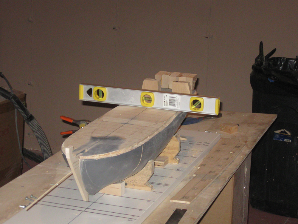
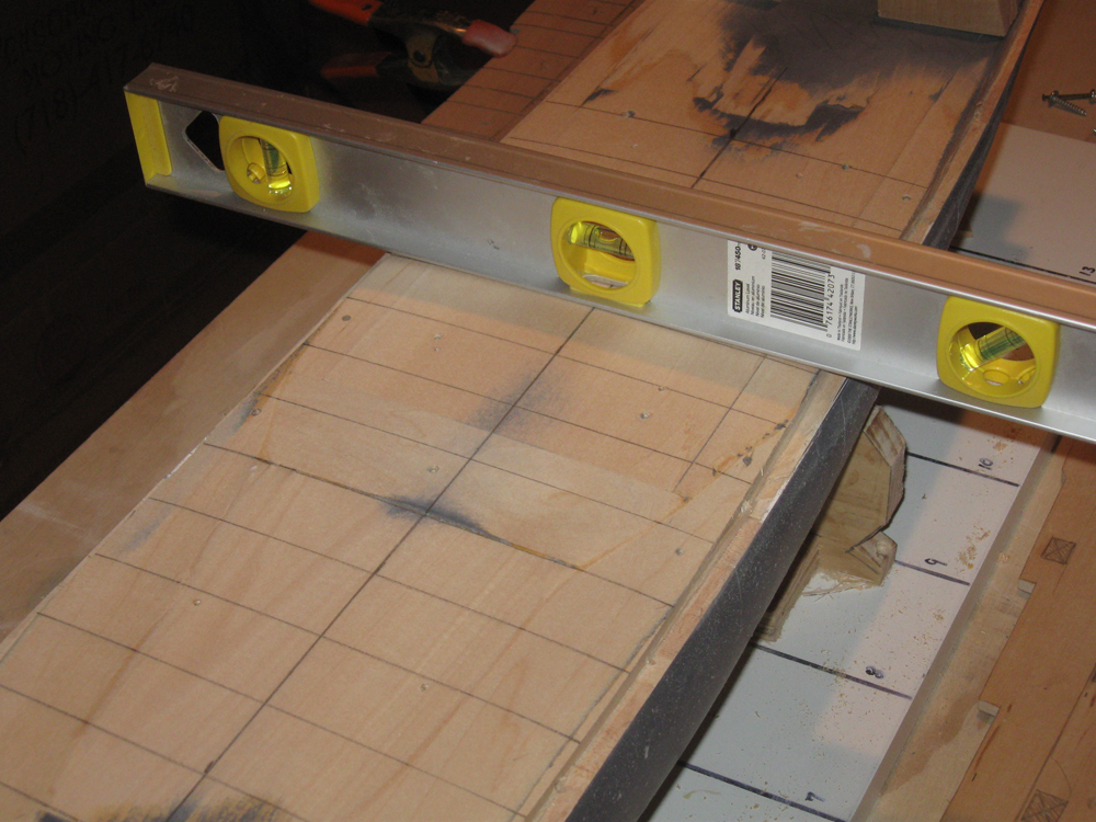
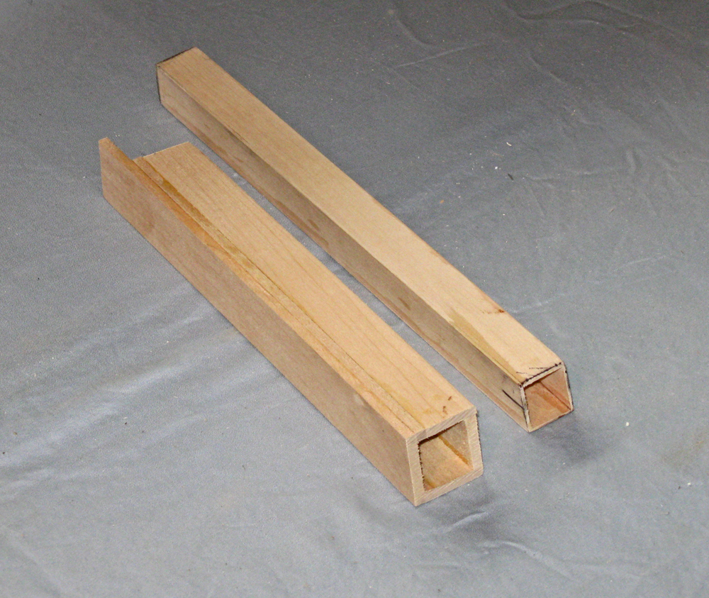
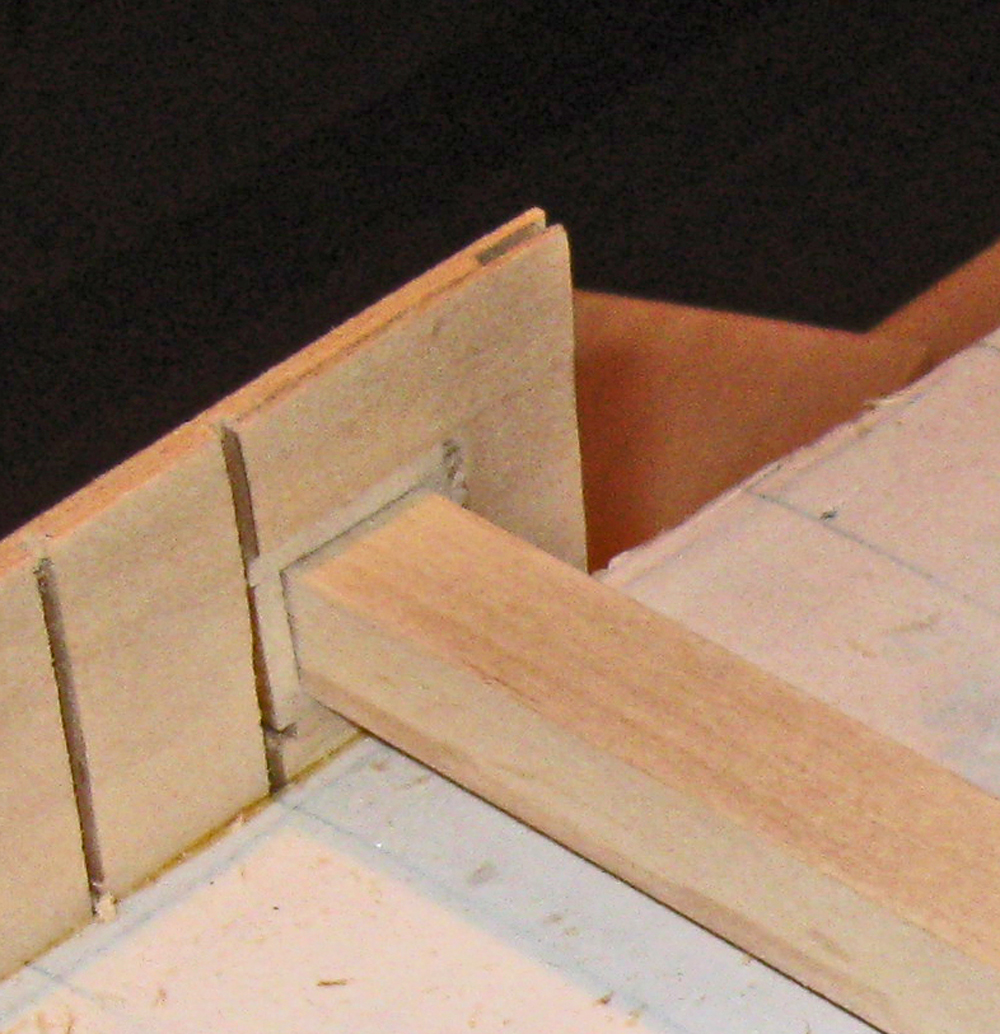
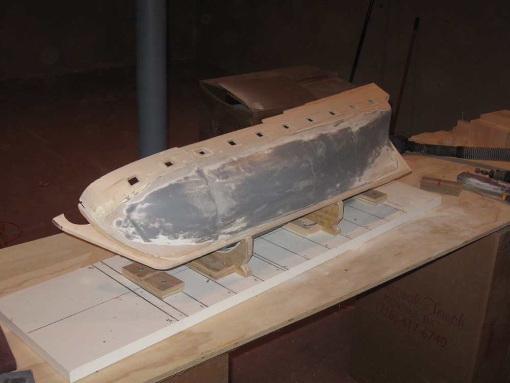
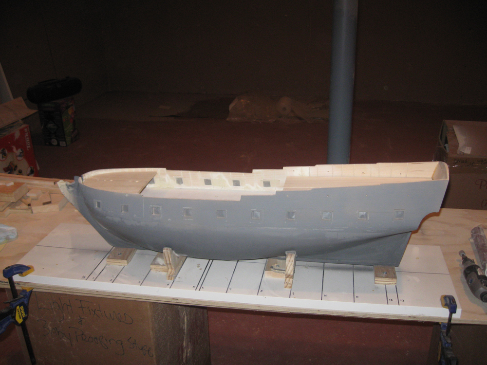
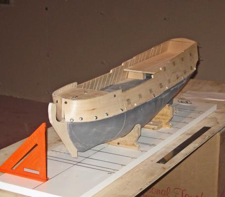
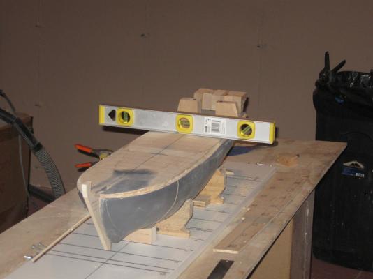
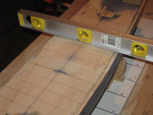
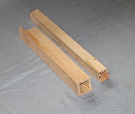
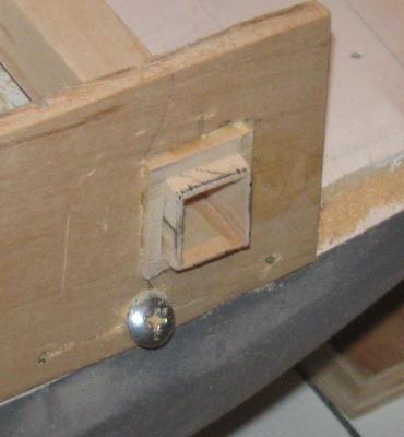
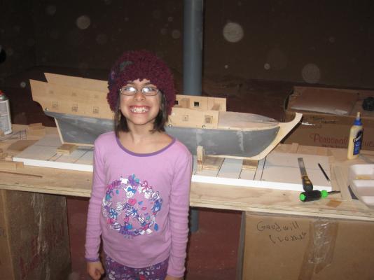
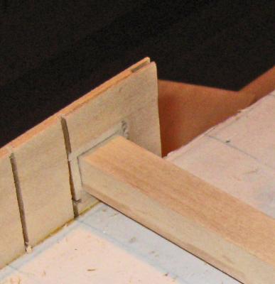
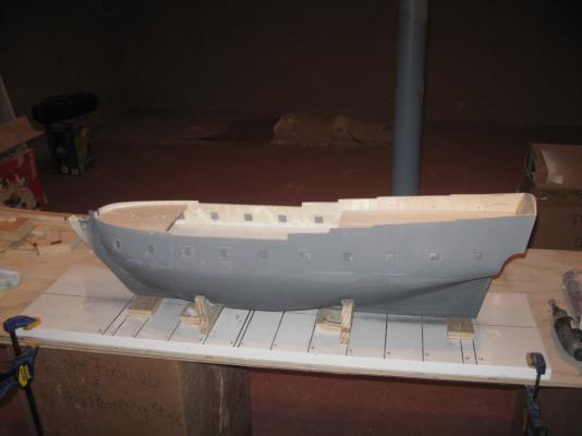
Hi all. Thanks for the likes and the compliments. They helped me weather the weather this snowy winter. The last time I showed the hull was at the end of January, and it looked like this. Here is how it looked five weeks later, including getting snowed in for a week with the model in the shipyard. This is how it got there. After the bulwark pieces were cut, fitted and bent to shape, they were left to dry completely, then removed from the hull so the deck structure could be addressed. After carefully levelling and squaring the building board and the model on it, the level was placed across the deck. The symmetry and camber of the deck was read under the straight lower edge of the level. To insure that the readings were accurate I drew the centerline and a series of perpendicular lines athwartships. The level was placed on each line and high spots were identified then sanded down. Using the lines and the edges of the basswood lifts as guides, the deck surface was smoothed and given the proper camber and sheer. Now I prepared the model for its ultimate mounting. It was flipped over and I drilled two ¾” holes into the centerline and about 2 inches deep, spaced well apart. Into them I glued 1 inch long pieces of dowel that had been drilled out to accept 3/16” T-nuts on their upper end. They were mounted so they came just proud of the surface of the hull. Once the glue was dry they were sanded flush. The stem, keel and sternpost were cut and fitted. They are 3/8” maple and secured with bamboo pegs into the hull. No attempt to make scarf joints was made since the lower hull below the waterline will be shown with a coating of “white stuff” as teredo protection. Matching holes were drilled in the keel to allow 3/16” bolts or threaded rod to screw into the T-nuts to hold the model down to its ultimate cradle. Unfortunately I did not pause to record this work. I was distracted by a very pretty assistant, a friend of my granddaughters, who showed some real interest in what I was doing. To her I am Poppy Dan the Boat Man. She was that third hand that comes in so handy from time to time. Maybe she will keep at it. She has just helped me install the aft bulwark pieces into their final homes. They are glued into the rabbets in the lower hull and pinned with bamboo dowels. Temporary internal supports are screwed to the deck to maintain the 13 degree tumblehome. Next I turned to the gunports. On my gun station practice piece I cut out the opening cleanly on the band saw. This was impossible with the bulwarks, so the openings were roughed out with a zip-bit in a Dremel. It made quick work of cutting the openings, but was prone to wandering, especially when it crossed one of the slots for the kerf bending of the bulwarks. These were squared up with a rasp and various files. Unfortunately, my skills were not adequate to squaring and locating the openings precisely, nor smoothing them well enough to fit the inner lining tube. I reasoned that if the lining tube would give me a square opening, then a larger tube would give me a square frame for the lining. I put together a tube for the frames from 1/8” basswood which was sized so the lining tube slid neatly inside it. Now a larger opening could be cut in the bulwarks and the frame located inside it. The frame could be adjusted within the opening with shims before being glued in place. The inner lining tube was slipped through to insure that the frame was set vertically and at the correct height. All of the port side gunports were done in this way. The lining tube was used again for the starboard ports to make sure that they matched the port side in location and height. Not only were the ports matched using the lining tube, but with the cannon that will ultimately be installed through them. At the forward end of the bulwark pieces a slot was cut up its edge before it was installed. A matching slot was cut in the aft edge of the forward bulwark pieces and a hardwood spline inserted across the joint to align the pieces and prevent future movement under the planking. The forward pieces were installed and pinned in place, the spline glued between the pieces. The two forward gunport frames were cut, dressed and installed as before. At the stern the transom piece was installed and blocks for the counter were cut, installed, and smoothed, ready to be covered by planking. The upper two inches of the bulwarks all around were sanded to narrow the top edge to scale 9” and a hollow was sanded into the exterior of the aft bulwark at about the level of the gunports. The effect is subtle, but the combination of the two operations created the shallow “S” curve and tapered top timber shape seen in the plans. The entire exterior of the hull was filled with Durham’s Rock Hard Water Putty as were the kerf slots on the inside of the bulwarks in all areas that will be visible in the finished model. Several rounds of sanding, filling, and more sanding were necessary to get the lower hull to a proper smoothness. When it was done the filled areas were hardened with Minwax Wood Hardener for strength and longevity. When it was dry there was a final sanding and a first priming. This revealed some more spots that needed to be filled, sanded and hardened. After a few more rounds the hull was given a final priming ready for painting. Looking at the plans it is clear that the lines of planking all take their curves from the line of the main wale. I decided to define this with the top edge of the hull paint as a test of the location and sweep of the curve. It was plotted from the plans and masked off above the line. Several coats of off-white enamel were sprayed on, giving the lower hull a hard finish that will support the final color coats. The demarcation line for the wale looked good . Finally, the fun of planking and detailing the hull can begin. Dan


- 241 replies
-
- 13
-
-
- queen annes revenge
- pirate
- (and 2 more)
-
Hi Cap'n - Just got around to reading through your log. An hour very well spent. I have seen the Lettie many times at South Street Seaport and sailing around New York harbor. I always thought that she would make a really pretty model, and you are doing her the justice she deserves. I'm pulling up a chair and looking forward to seeing the painting and detail work. Be well Dan
-
Hi Michael - Your shop makes me green with envy. Straightening and rearranging will save you much time in the future. I know that whenever I am stumped for a solution to a building problem I clean the shop. Many times the answer comes up from my subconcious while I am chasing dust bunnies. The work looks great, as always. Where did you get your line? Morope, Syren, or somewhere else? Be well and stay warm. Dan
-
Hi Mark - Coming along nicely, as everyone says. v.2 will be a significant upgrade from v.1. Then again, I'll be looking forward to v.3 . . v.4 . . v.5 . . :-)) As for the glue line, I don't think that you have to worry overmuch. The human eye will fill in any missing sections when viewing the completed model. The stem looks good as it is. Your technique is working well. One suggestion, derived from hard experience, is not to drill the bobstay holes yet. Just pencil them in for now. Their location will be determined by the final length of the bowsprit, the exact location of the collars, and the type and thickness of your ropes. I have had to plug and relocate the hole for the inner bobstay when the stay fouled the stem and figurehead. Now I wait till I am doing the rigging to drill the holes. Of course, if you are not planning on rigging her, then drill them where they look good and ignore this stray thought. Be well. Dan
-
Thank you all for the likes. It warms my heart during this excessively cold and snowy winter. Doris - Thank you so much. High praise from someone whose own work quality is second to none. I will get a chance to work on the hull this coming week, and I will see how the lessons of the gun station translate to the model. Be well Dan
-
Hi Mark - Good point. I will add them to the model. Thanks. Dan
- 241 replies
-
- 1
-
-
- queen annes revenge
- pirate
- (and 2 more)