Dr PR
-
Posts
2,384 -
Joined
-
Last visited
Content Type
Profiles
Forums
Gallery
Events
Everything posted by Dr PR
-
It's made from tough football helmet plastic!"
-
Sigbjorn, Looks like you have already started a build log. Just add more posts to this thread as you go along. Take your time and enjoy this build. It is a beautiful ship.
-
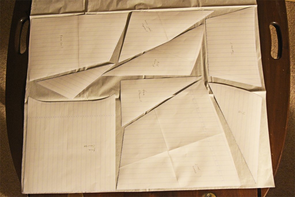
 I printed each sail to produce templates for cutting them from the silkspan. I have been around a while, and have used many printers, so I know that some of them do not print 1:1 accurately. On one HP laser printer I owned I had to set the scale to 1.0623:1 to get accurate print sizes. So I put a ruler in every CAD drawing to allow checking the size. To my pleasant surprise, my Brother laser printer prints exactly 1:1 when I set the print scale to 1:1. Here is a photo of all the sails laid out on a 36" x 24" (914.4 x 609.6 mm) sheet of silkspan. A quick arrangement takes half a sheet of silkspan. Wow! Up to now these sails have just been images on my computer screen and not all that large. But when I printed them out many were too large to fit on a 8 1/2" x 11" sheet (~A4) of printer paper. I had to tape two or four sheets together! This is the main sail (main gaff sail) with my hand for a size reference These things are big! It's a good thing I got several sheets of silkspan!.
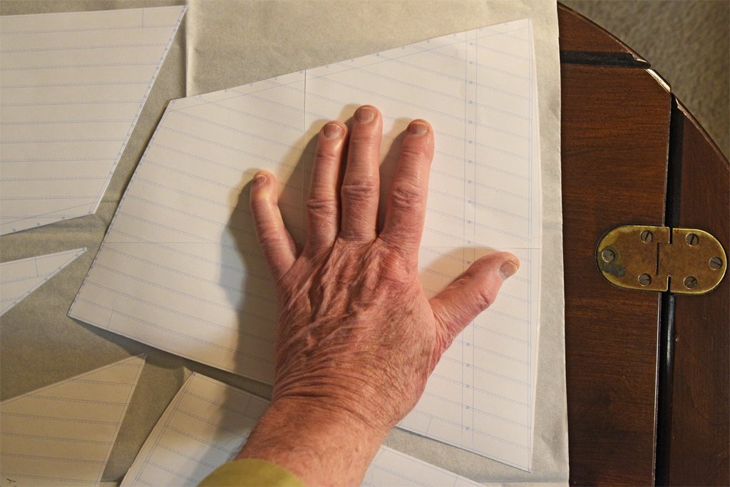
-
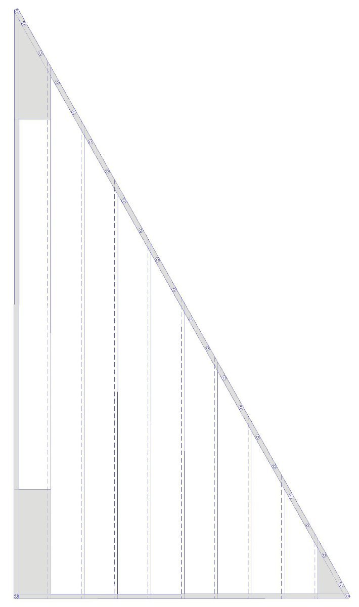
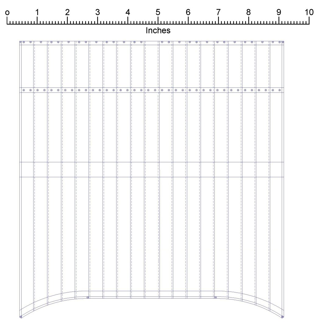
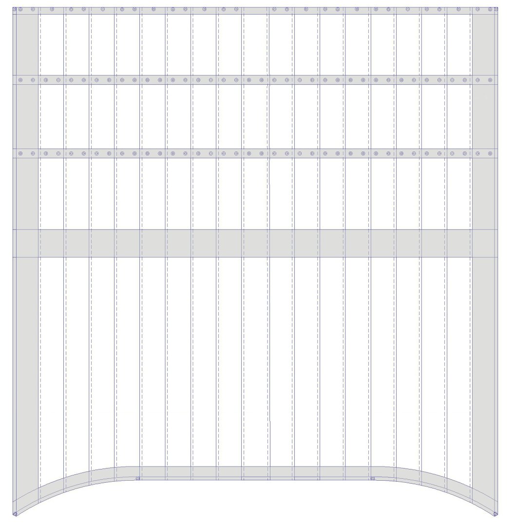
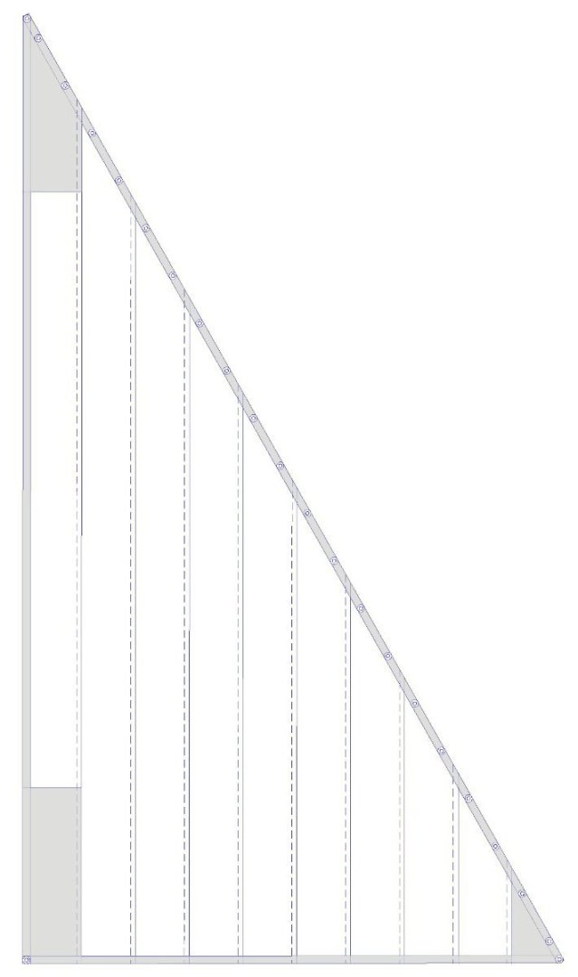
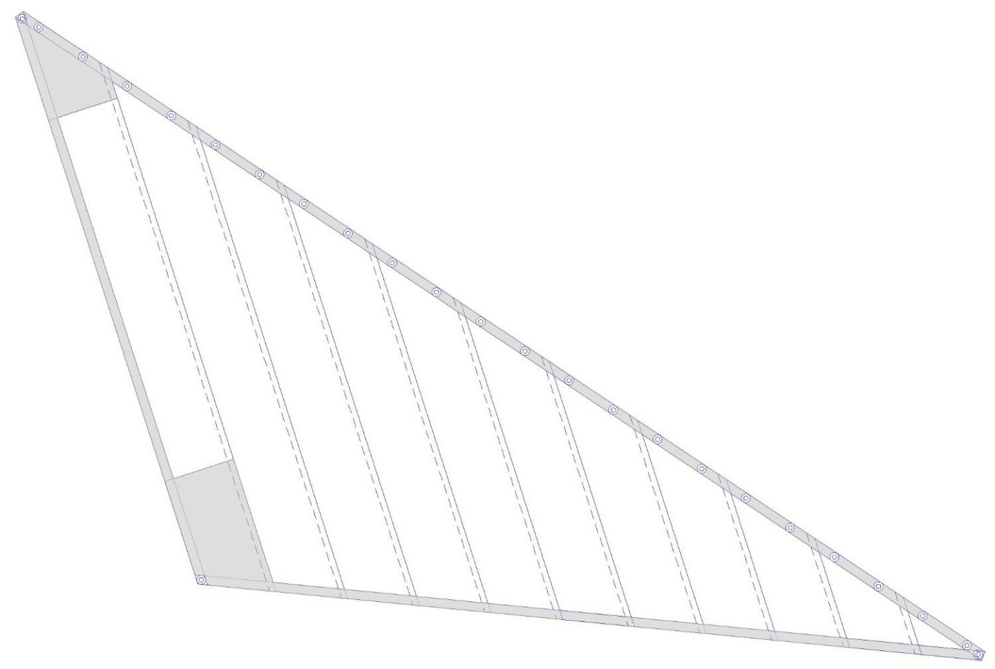
I looked through Steel's book and it is mostly what Lees said. And of course it talked about sails for an English square rigged ship. The British Admiralty was very conservative, and resisted any changes to the way things had always worked. American topsail schooners were rigged more "aggressively" than British ships - until the Brits figured out they couldn't catch them with the smaller British top hampers. So the dimensions given in Steel and Lees don't always work for Baltimore clippers. Here is the fore topsail. It has the basic features shown in Steel and Lees, but configured for the schooner. The rough dimensions were determined by mast height and the length of the fore course yard and topsail yard. The actual width at the head was 13 24" cloths wide, with a 2" overlap at the seams. Tablings (gray) on the back of the sail were 3" wide on leeches and foot, and 4 1/2 " wide at the head. Linings (gray) were on the front of the sail and were one cloth wide on the left and right leech, and half a cloth wide at the foot. The center cloth had no grommets (holes) at the top for robands to tie the sail to the spar. Then the next outer cloth had two holes, then one, then two, and so on. Each corner had a grommet/cringle for lines to attach the sail to the yard arms and to the clews and sheets. The fore course was more complex and similar to that on a square rigged vessel. The dimensions were determined by the mast height and fore course yard width. The yard was suspended below the trestletrees 1/10 the length of the fore mast from partners to hounds. The center of the foot of the sail was 7 feet above the fo'c'sle deck. The sail is more or less rectangular, 19 cloths wide. The tablings were 6" on the head and 3" on the leeches and foot, on the back side of the sail. The linings were on the front side and were 1 cloth wide on the leeches and 1/2 cloth wide at the foot. The grommets for robands at the top were the same arrangement as with the topsail. Some authors say there were two grommets in each cloth and some say only one. There was a horizontal middle band half way down the sail that was 1 cloth wide. The reef band was down 1/6 the height of the sail at the center from the top. It was 8" wide, and had two grommets for reef lines in each sheet. Some authors say there was only one grommet per sheet, either in the center or at the seam between sheets. If there were two reef bands the second was 1/3 the height from the top. The bottom of the sail was curved down 3 feet from the buntline grommets outward, and straight between the buntline grommets. The configuration of both of these sails is somewhat simplified, with fewer linings and reef bands than sails on larger vessels. And it is similar to what Lees and Steel say for sails from about 1811 through 1845. There were differences in other periods.
-
Tiny Spar on 17th Century English Yacht
Dr PR replied to catopower's topic in Masting, rigging and sails
I found a possible answer to this puzzle: This definition is given in Steele's The Elements and Practice of Rigging and Seamanship, page 87" "HEADSTICK. A short round stick with a hole in each end, strongly sewed to the head of some triangular foresails and jibs, to prevent the head of the sail from twisting; the head-rope is thrust through the holes before it it sewed on the sail." Here is a drawing (Plate 25, before page 129) of a "sloop's jib" from Steel showing the "head stick". " ... the rope on the hoist put through the holes in the head-stick; then served with spunyarn, and spliced into the leech-rope. The head-stick is seized round the middle to the head of the sail, and a thimble seized in the bight of the rope."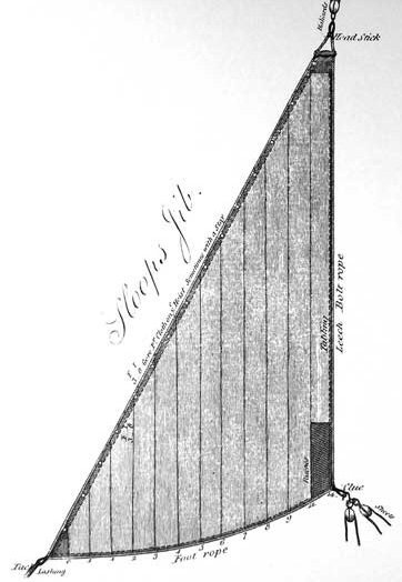
- 19 replies
-
- 10
-

-

-
George, Thanks for the reference! I will read it and check my calculations. Better to discover a mistake now before I have cut any material! But you are right about the variability of sail design. In one sail making text I read it said the sail maker got the dimensions of the yards/spars and about where they were positioned on the mast, and from these dimensions fabricated a sail. Drawing on the lore and normal practice the cloths were cut individually and sewn together. The resulting sail actually determined the final positions of the yards and spars relative to each other. So sail plans were just used for guidance, and the final result may be different. I'm sure that is what will happen on my model!
-
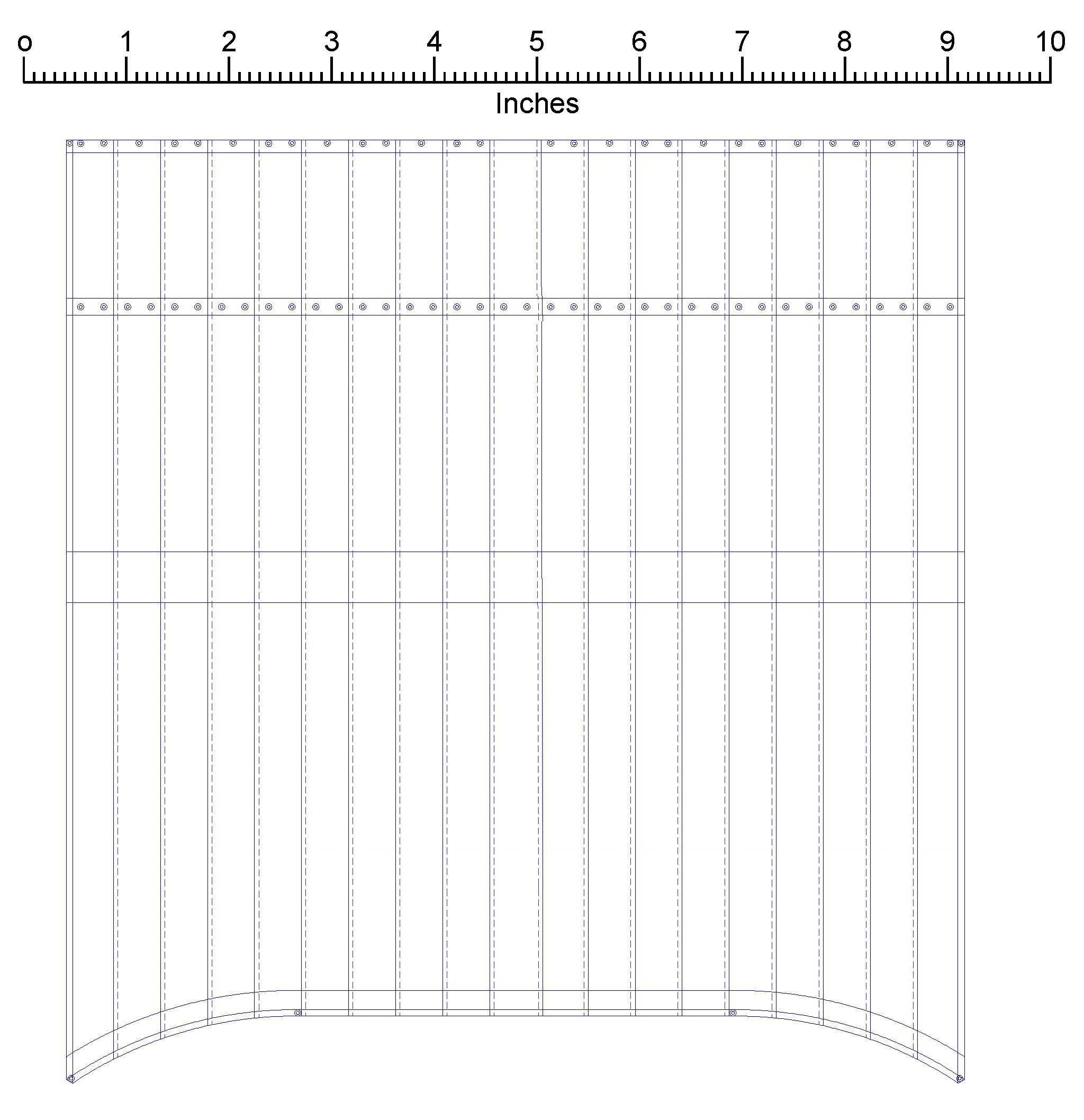
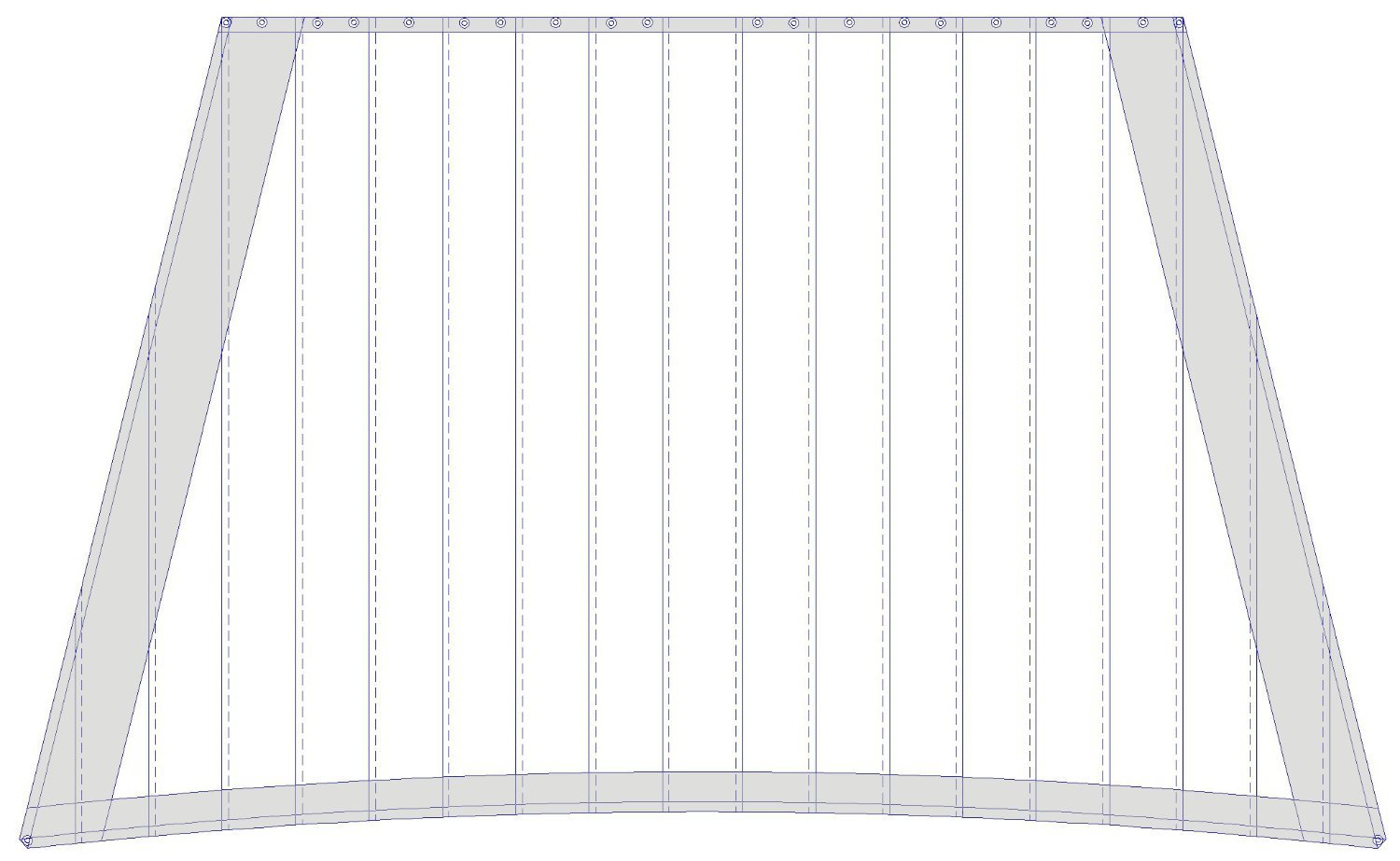
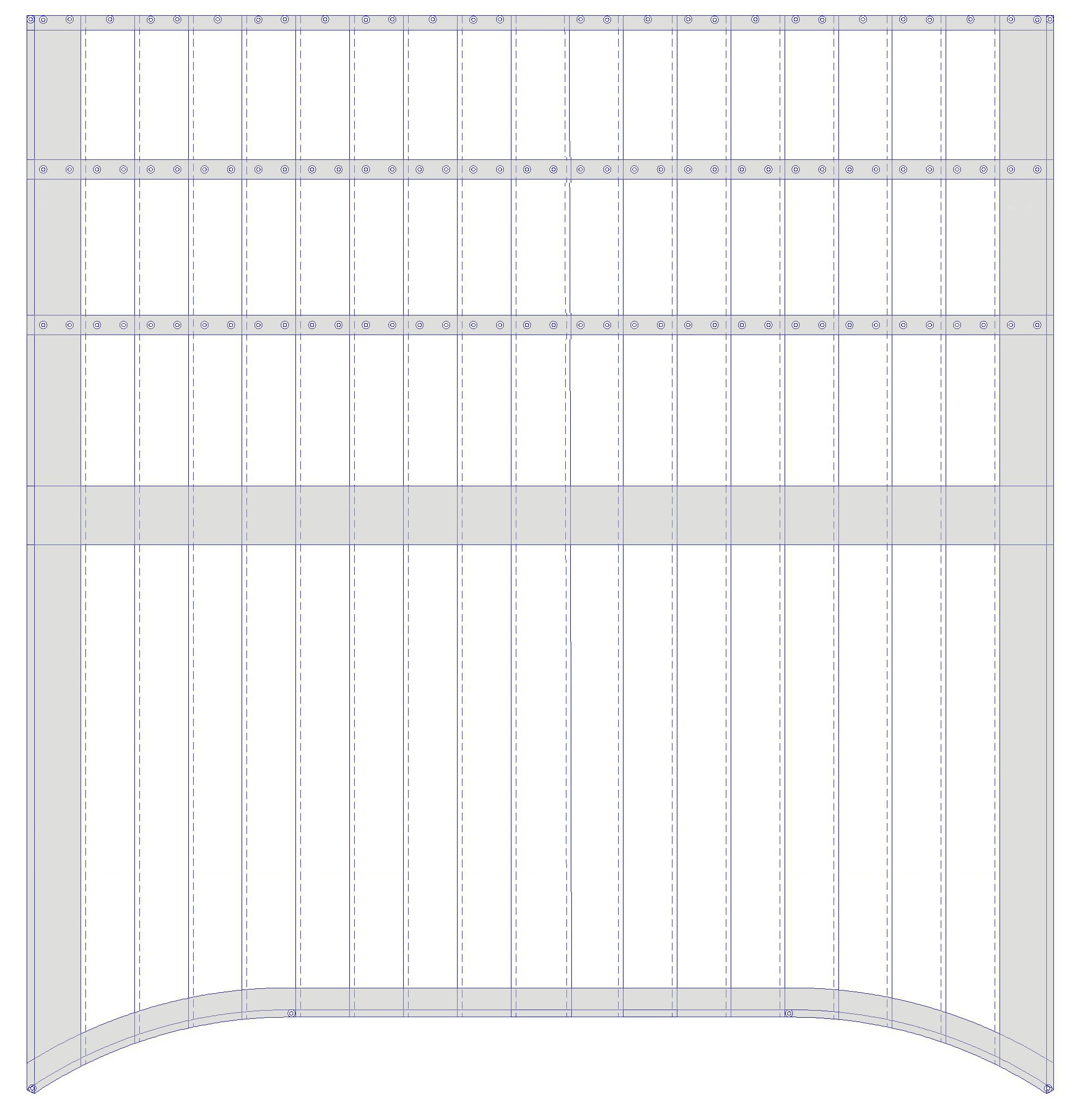
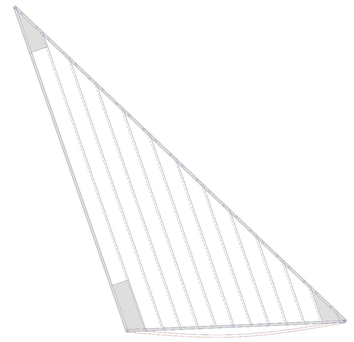
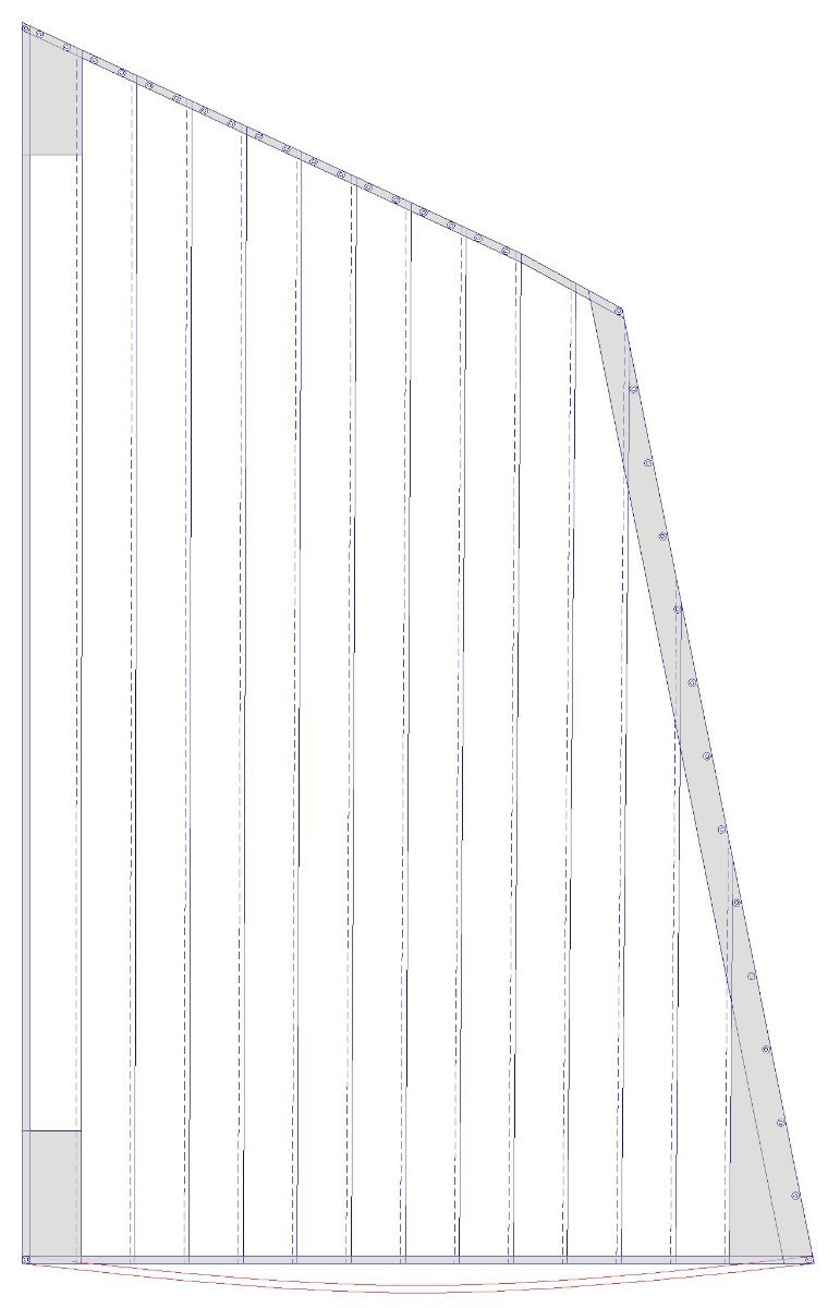
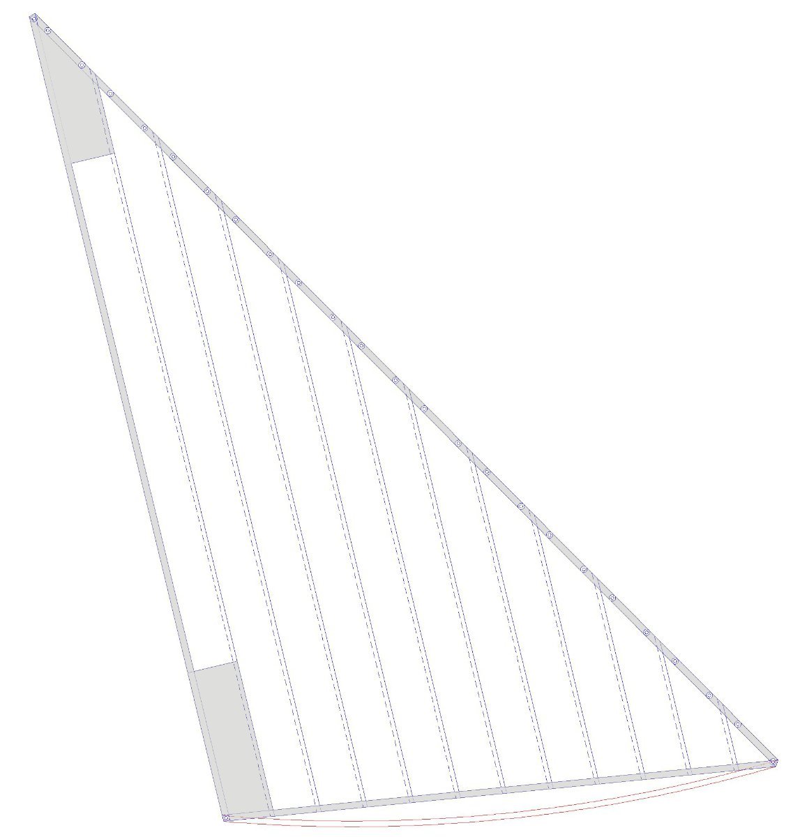
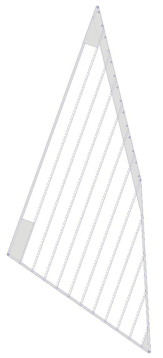
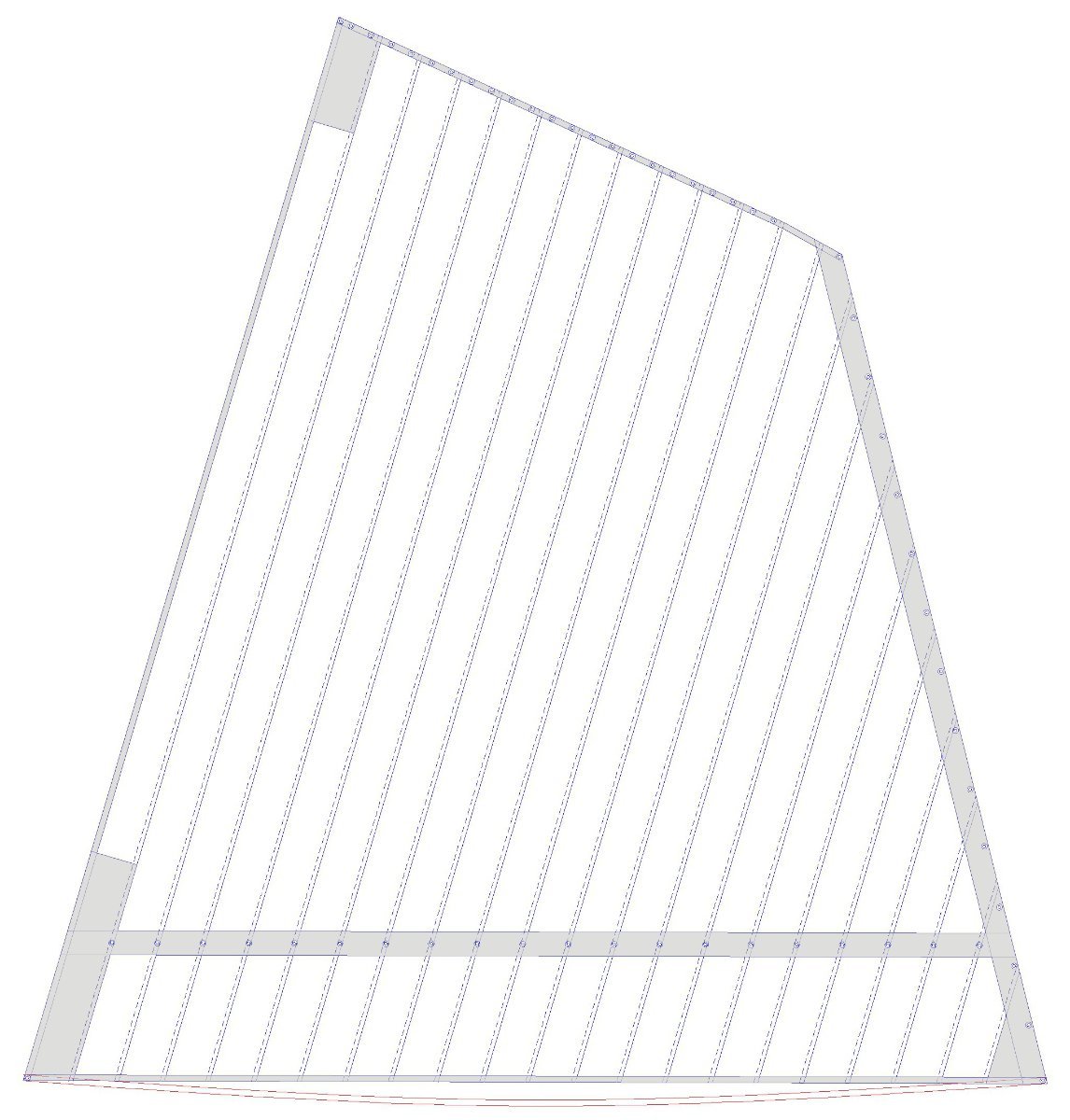
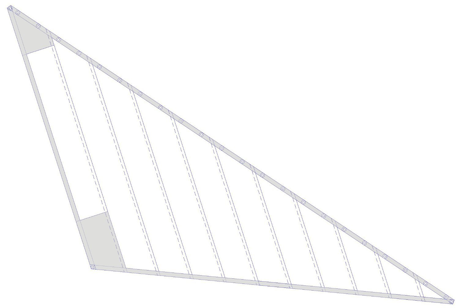
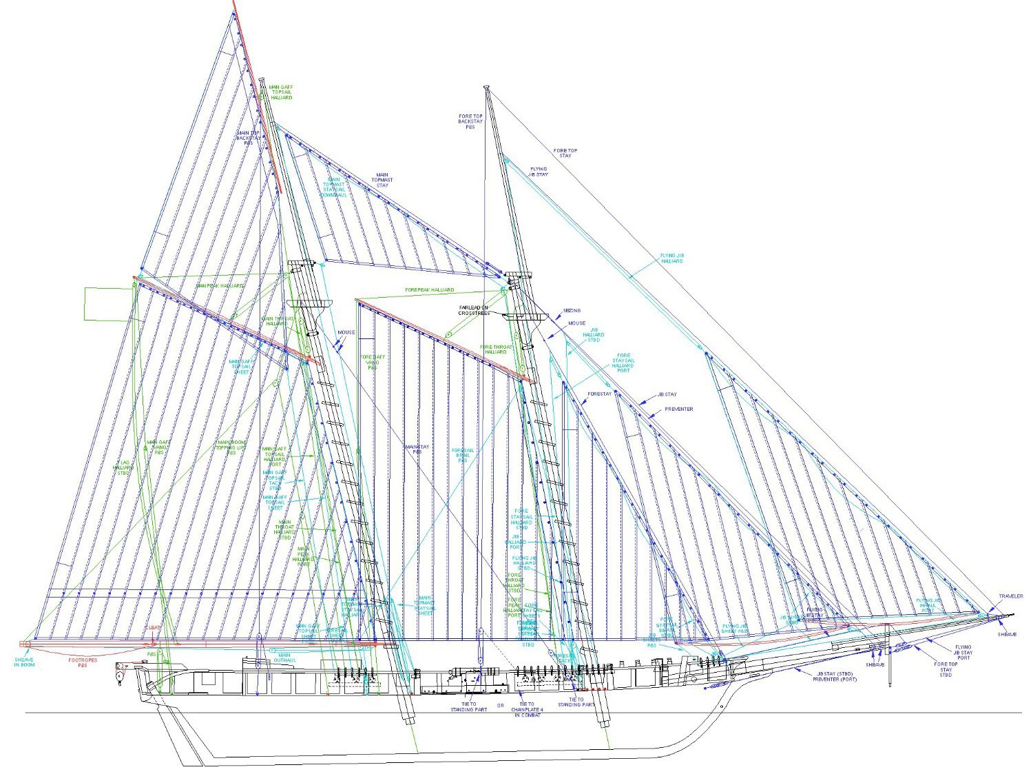
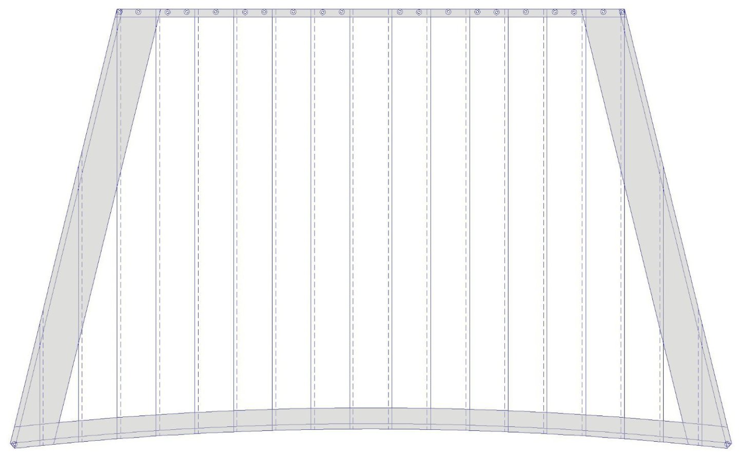
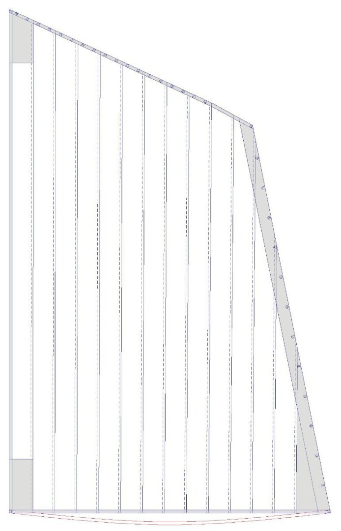
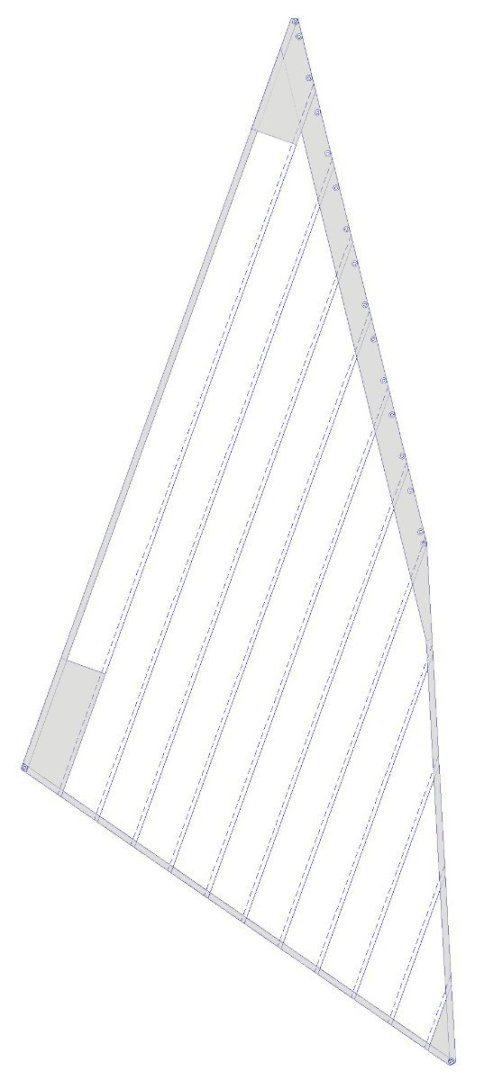
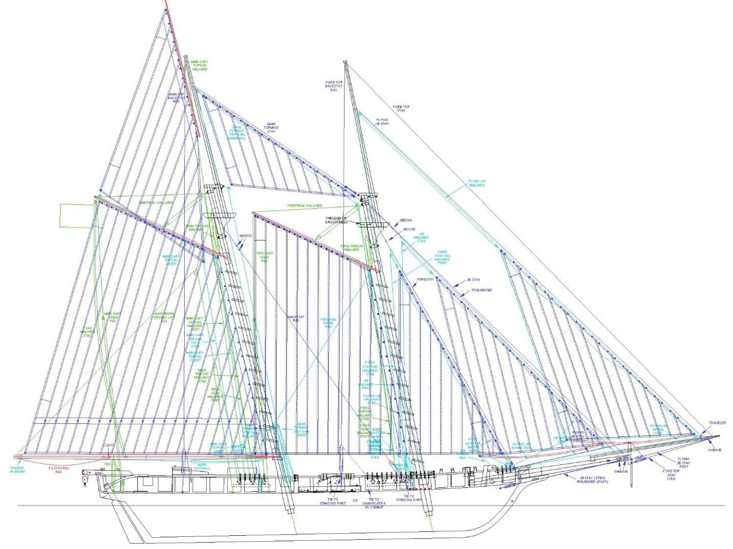
SAILS I have pretty much developed the sail plan for the ship. Here I will talk about the fore-and-aft sails, and I will deal with the square sails in another post. I plan to follow the procedures in Tom Lauria's YouTube video Making Sails for Ship Models From Silkspan. https://www.youtube.com/watch?v=g_m_VWzk4w8 However, because this model is 1:48 scale I will add the boltropes (to be described later). NOTE: The first thing I did was measure everything on the model (mast heights, stay lengths, etc.) and made sure my CAD model has the correct dimensions. Some things had changed since I restarted this build four years ago! NOTE: The dimensions and proportions shown here are about right for the first quarter of the 19th century (1800 - 1825). They were slightly different for other periods. I consulted half a dozen books to learn the "rules" for sail design. Most were really interested in large square-rigged ships, but I have some books specific to fore-and-aft rigs. As usual, no two authors agreed on the details, but the general ideas were there. The main sail - the gaff rigged sail on the main mast - is the largest and contains all the elements of the remaining sails. Here the forward edge (luff or forward leech) is on the right side of the drawing and the leech (or after leech) is on the left. The length of the head (top) and foot (bottom) are determined by the length of the gaff and boom. The forward corners attach to eyebolts on the gaff and boom. The after corners are forward of the gaff/boom ends to allow rigging to a block or sheave. The height depends upon how high the gaff is rigged. The angle of the top of the sail is determined by the angle of the gaff - it ranged from 25 degrees to 30 degrees on schooners. Here is it 25 degrees. The sail is made up of "cloths" 24 inches wide, running parallel to the after edge or leech of the sail. From the 15th century on the width of these cloths varied, but was often 27-28 inches. By the 18th century in England and the Americas the width had become 24 inches. Each individual cloth was sewn to its neighboring cloth with a 2 inch overlap. I do not intend to sew together individual cloths, but will mark the seams with light pencil. Around the edges of the sails is a second layer called the "tabling." Some authors call this the "lining." However, other authors reserve "lining" for the additional pieces added at the corners of the sails. In addition, there is a reef band 1/6 up the forward edge or luff of the sail. Larger vessels could have up to 4 reef bands. All of these pieces are shown in grey. Edit: The tablings were the folded over edge of the sail cloth that was stitched to provide strength to the edge of the cloth. Tablings were usually placed on the port side of fore-and-aft sails and the after side of square sails. Some authors say the linings were on the starboard side of fore-and-aft sails and the forward side of square sails. However, I have read a few books that say the opposite about tablings and linings! Some say the tablings and linings were on the port side of fore-and-aft sails. Reef bands were on the forward side of square sails and on the starboard side of fore-and-aft sails. They were sewn under the edges of the linings for extra strength. On author claims the reef bands were sewn on both sides of the sails for extra strength. I also show a possible downward curve (roach) in the bottom edge (foot) of the sail. I am still trying to determine how common this was, how deep it ran, and if it was commonly used on schooners. In this case the sail will not be lashed to the boom, but will be attached only at the clew and tack. Different authors describe different widths for the tablings. I have used tablings that are 3 inches wide across the head, leech and foot of the sail. Some authors say 2 inches wide at the foot and leech and 3 1/2 inches wide at the head. The forward edge, or luff, has a strip made of a 24 inch piece doubled over to 12 inches wide. The reef band is 1/4 the cloth width, or 6 inches wide. The linings are 24 inch wide pieces attached to the starboard side of the sail. They extend about 3 feet from the upper (peak) and lower (clew) corners, but where there are reef bands they extend up to 1 foot above the highest reef band. At the lower forward corner (tack) the foremost cloth is doubled. I have drawn two holes or grommets per cloth across the head of the sail. Some authors show only one hole, in the center of the cloth. Some show one hole, positioned at the seam between cloths. Another says there should be a single hole in a cloth, two in its neighbor, one in the next, two in the next, and so on. Take your pick. The forward edge (luff) has holes positioned at the spacing of the mast hoops around the mast that the sail is attached to (not to be confused with "mast hoops" that fit tight around the mast for structural strength). Spacing was generally 24-30 inches. The hoops were at least 1 1/4 the diameter of the mast so they could move along the mast smoothly. Some authors say the sail had two holes for the hoop lacing to pass through, but others said only one hole. I have chosen to use one hole. However, some authors say sails had cringles (short pieces of rope) laced to the bolt rope for the attachment points instead of grommets or holes. Now let's look at the other sails. In all of these drawings the cloths are 24 inches wide and can be used for scale measurements. The fore gaff sail (left) is similar to the main sail. Perhaps it should have a reef band (to be determined). The fore staysail (right) is triangular, and the construction is generally the same as for the trapezoidal (4 sided) sails. However, the rules for the size of the triangular sails are more complex. The side laced to the supporting stay (head of luff) was sometimes called the "stay," if for no other reason to confuse as to whether an author meant the stay (rope) or the stay (leading edge of the sail). The stay/luff of the forestay sail was supposed to be about 4/7 the length of the forestay (rope). But what is the" length?" Is it from the lower end of the stay to the mast head, or up to the mouse or seizings forming the loop around the mast? I chose to use the length from the bowsprit to the mouse, because the sail cannot extend up beyond the mouse. Starting at the lower forward corner, the tack, I measured up the forestay the required distance. The leech extended down to the height of the bottom center of the course. The foot length was calculated as a "little over" half the width of the course (to be described later). The clew (bottom aft corner) of the sail was to be cut at a right angle, so I used geometry to determine the configuration with the proper foot and leech lengths coming together at a right angle. Next the jib and flying (outer) jib. These two sails are very similar, the jib on the left and the flying (outer) jib on the right. The stay/head of the jib is 3/4 the length of the jib stay/preventer (ropes). Again, I used the distance from the lower end of the stay (rope) up to the mouse. The leech is 3/5 the length of the jib stay. The foot is about the length of the boom, or in this case, the bowsprit. The leech should be about 1 1/2 the length of the foot. These calculations varied over the years, so check the date of your model. The flying (outer) jib stay/luff is 4/7 the length of the flying (outer) jib stay (rope). None of the calculations for the leech or foot worked to complete a triangle shaped anything like a jib (either the leech and foot ends would not meet or the sail was ridiculously narrow from clew to stay. So I made the foot about as long as the jib boom, ran the foot a bit below horizontal fore to aft, and connected the peak to the clew to get the leech. It looks like the flying jibs in drawings of topsail schooners. Note: The foot of the triangular foresails should be about as long as the bowsprit, jib boom, or flying jib boom. It doesn't have to be exactly as long, but about the length of the associated spar. When in doubt, this is a simple rule to follow. This leaves the two fore-and-aft topsails. The main gaff topsail (left) was four sided, but almost triangular, with the topsail spar almost vertical behind the mast in the American version. On European vessels the spar was closer to horizontal, making a trapezoidal sail. The dimensions are determined by the length of the gaff and the topsail spar, leaving enough space for the corners of the sail to attach to the spar ends or running rigging for the sail. The tack extended below the gaff. The leading (luff) edge had a 12 inch wide lining for added strength. The main topmast staysail (above) rode on the main topmast stay (rope) between the main topmast and the cap of the foremast top. It was attached to the stay with hanks (robands) or with a lacing, depending upon the vessel. The length of the sail stay/head was shorter than the stay (rope) enough to allow rigging to the foremast and the main topmast. The leech extended down to where it was rigged to a block on the main mast top cap. The foot was long enough to fill the space between the foremast and main mast, with allowance for the sheet and block at the mainmast head. Two of my references for this were Lees' Masting and Rigging and Mondfeld's Historic Ship Models, but these just had the rules for square rigged ships, and they sometimes didn't work on the schooner. Marquardt's The Global Schooner provided some rules, but not enough to actually design the sails. So I blended information from all sources to arrive at these sail designs.


-
CV-59 USS Forrestal Carrier
Dr PR replied to GZM2023's topic in Building, Framing, Planking and plating a ships hull and deck
Is this a display model or R/C? Choose your materials carefully if it will be outdoors and exposed to direct sunlight. Wood doesn't expand much when heated. Metals expand a bit more, and plastics expand a lot! A fellow in Australia built a 1:72 R/C carrier with a wooden hull and plastic (styrene or Plexiglass) flight deck and hanger sides. In sunlight on a hot day the flight deck buckled upwards and the hanger sides warped and pulled loose. A two meter (6 ft) long piece of acrylic will expand about 5 mm (1/4 inch) in length with a 20C temperature rise! -
Piotr, I am happy that you find my posts helpful. I have learned much from other members of the forum! I have posted general details of topsail schooner rigging here: https://modelshipworld.com/topic/25679-topsail-schooner-sail-plans-and-rigging/?do=findComment&comment=750865 I describe each spar and sail and how the running rigging connects to them. In some cases there are several options Another thread talks about belaying options: https://modelshipworld.com/topic/30234-topsail-schooner-belaying-plan/?do=findComment&comment=862302 This is just a preliminary plan for the model I am building. I have made a few small changes while creating the actual rigging, but the general ideas apply to all vessels. Figuring out how to run all of these lines without tangling them is very difficult to imagine on paper or computer. In the long run you will have to work it out on the model, as they did on the real vessels. And no two ships will be rigged exactly alike. I am just starting to measure each sail and plan how to make them. As I rig them I will post pictures and descriptions. It will be interesting to see how close my original plans made on the computer match what I finally come up with! The best laid schemes o' mice an' men Gang aft a-gley. Robert Burns
-
I have had little trouble with Duco (nitrocellulose in acetone) type glues on models. There are not many stresses involved if the parts are shaped correctly. However, I have seen two types of failures: 1. With soft wood (balsa) I have seen broken joints where the glue adhered well to one side and the wood broke away from the glue on the other side. This left the glue with bits of wood embedded in it. 2. I used to plank hulls (single layer planking) by applying glue along the edge of the plank being installed - to join with the neighboring plank edge - and to the bulkheads. I have never seen a plank break away from the bulkheads, but because of swelling and shrinking of the planks due to temperature and humidity changes gaps have appeared between planks, even on painted hulls. The best solution I have found to this problem is to paint the entire interior surface of the planking with thin epoxy paint, also covering the join between planks and bulkheads. The epoxy soaks into the wood creating a tight bond between all pieces. I have been doing this for about 40 years and have never seen a crack develop between planks on single layer planking.
-
Finished? All of it? I'll bet you are glad to have that behind you!! I remember when you started using the insulated electrical wire for the piping. It isn't a common modelling material but for all that piping it is perfect. You can bend and reshape it many times to tweak the curves and get the right alignment.
-
I am not sure a small revenue cutter would have a coppered hull. Chapelle's The Search For Speed Under Sail (second printing 1983, page 208) says "many American schooners were copper-sheathed and fastened after 1795, though this was expensive until 1815. As late as 1822, however, the old lime-and-tallow, or "white bottom," was still being extensively used in the United States." The British began experimenting with copper sheathing in the mid 1700s, but had a lot of problems. Copper sheathing reacted galvanically with the iron fastenings, causing holes in the sheathing that exposed the wood to wood boring worms. It wasn't until the late 1700s that copper sheathing was used extensively in the Royal Navy. After the early 1800s copper sheathing was common on larger, more expensive American vessels. Commercial ships often did not have sheathing. Copper was expensive so it sometimes wasn't used on smaller vessels. Copper sheathing was said to have lasted only a few years and had to be replaced frequently up until the late 1820s when copper alloy fastenings were used to prevent galvanic erosion. Another consideration is the area where the vessel was operated. Wood boring worms weren't found in higher latitude cooler waters or fresh water. But if the vessel was to operate in equatorial waters copper sheathing was necessary. **** The color of the paints depended upon the cost of the pigments. Normally only the cheapest colors were used, except on large men of was and yachts. Chapelle's The Baltimore Clipper (1968, page 170) says yellow, black, green and blue paints were used on the hulls, with yellow or white bands. Other sources say American vessels generally followed British customs, but up until the mid 1800s the US Navy didn't have a standard paint scheme. The colors were left up to the ships owner or Captain, so there was a lot of variation. However, I have read that black hulls with yellow bands along the gun ports was common through the early 1800s. After about 1830 white bands were common, and white deck furniture and mast tops followed. There was no sudden change of fashion, and I have seen pictures of vessels with white mast tops from the late 1700s.
-
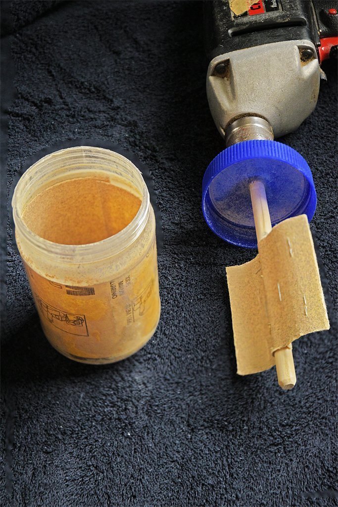
With my cobbled together tumbler I just ran the drill at "medium" speed - whatever that is. It is a hand drill with a variable speed "trigger" and a set screw to set the speed. I can lock it on so I don't have to sit there pulling the trigger. I let it run for 8 to 12 minutes (longer for larger blocks).
-
I have the entire series on DVD. I've had it at least 10 years and it cost less than $20. I have no idea how many times I watched this as a kid - every time it came up on TV. And then while in US Navy Officer Candidate's School we were shown episodes just about every day as part of our "training" (indoctrination). I still love to watch it! Gung Ho!
-
Very nice. You used a lot finer grit than I did (80 grit) and got the same results. So I looks like it doesn't matter much what type of sandpaper you use. How long did you tumble them?
-
I have used Duco cement to bond planks to end grain plywood bulkheads. It is an acetone solution of nitrocellulose. It soaks into the grain before hardening. It sets up in 20-30 seconds but forms the strongest bond after about 24 hours. It does have some odor, but no worse than cyanoacrylate. I always use some type of clamp or rubber bands to hold the planks in position overnight.
-
I made a simple device to round the edges of blocks. It worked fine on Chuck's blocks: https://modelshipworld.com/topic/19611-albatros-by-dr-pr-mantua-scale-148-revenue-cutter-kitbash-about-1815/?do=findComment&comment=981060 I used SIG SIG-Bond aliphatic resin model airplane glue and was careful to get glue on every mating surface. I let them set over night and then tumbled them. For times and results see the link.
-
Well, wish me luck on the sails! I have put sails on only one other model (Santa Maria in 1969) and they were paper sails supplied with the kit. I have made the attachments to belay all the running rigging associated with the sails so I need the sails for all those lines. There is a very good tutorial on YouTube for making silkspan sails. I bought enough silkspan for several ships. If at first you don't succeed ...
-
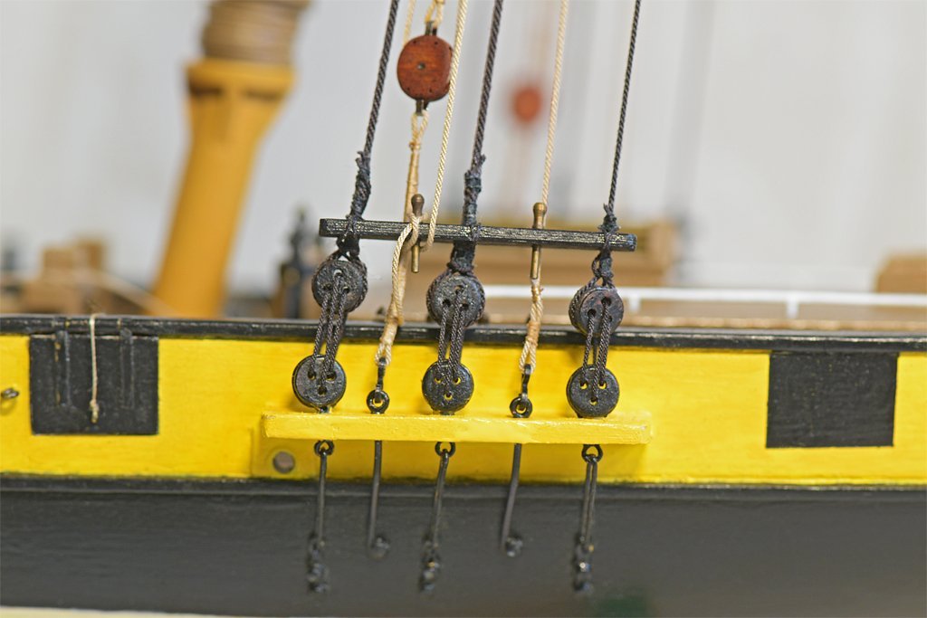
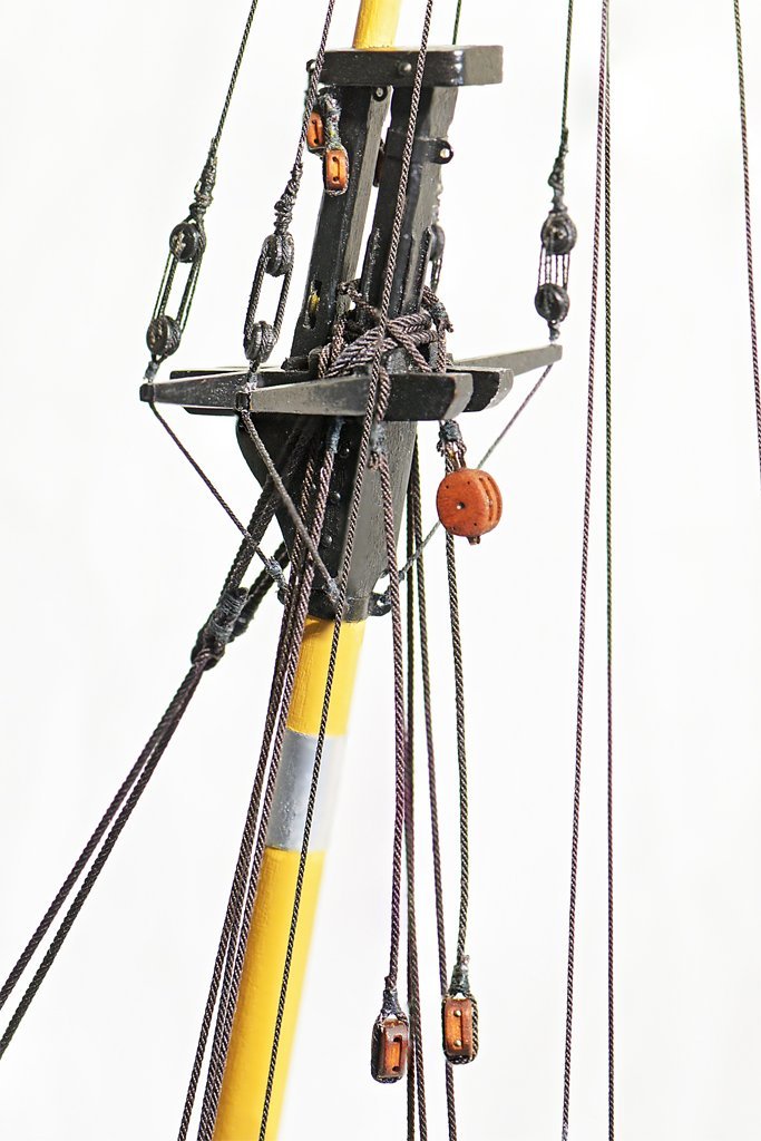
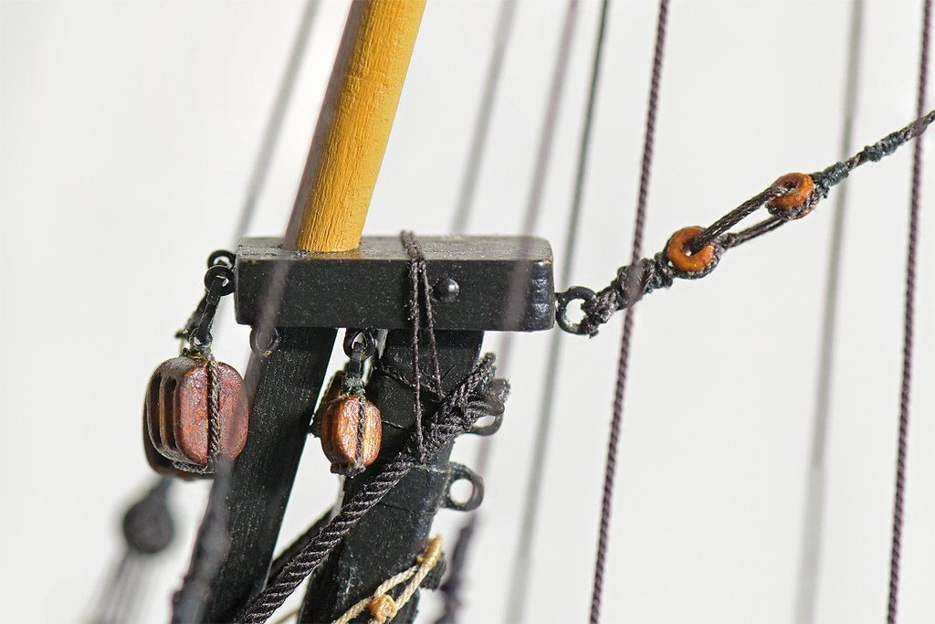
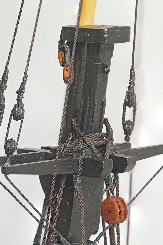
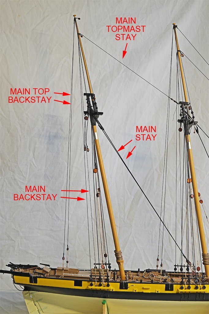
I have been working on the standing rigging for the main mast. After installing the shrouds I added the main backstays, port and starboard. These attach to deadeyes in the channels and secure to thumb cleats high on the topmast. Then the main top backstays were added, leading down from just below the truck at the mast top to luff tackles hooked to ring bolts in the deck. These are "running" stays. The windward stay tackle was tightened to support the mast and the leeward stay was loosened to allow the boom and gaff sail to swing outboard. After the backstays were done the main stays were added. There is a port and a starboard main stay, and they attach to luff tackles that hook to eyes on vertical timbers of the fife rail. These are both moused like the forestay. These also were running stays. Like the main top backstays (and the fore top backstays) the windward side main stay tackle was tightened and the lee side tackle was loosened to allow the fore gaff sail to swing outboard with the wind. Please ignore all the loose line ends laying on deck. I am still rigging the ship and everything hasn't been tidied up yet! Besides, I still don't know where everything will be belayed. The mainmast top isn't quite as complex as the foremast top. In the left picture above you can see the two pendants for the main boom topping lifts hanging from the aft crosstree. The right hand picture above shows the pendant for the main gaff throat halliard riding over the shrouds and the main stay lines. It has eyes spliced in the ends, and these are lashed together to close the loop as they are on the fore mast. The main topmast stay is secured above thumb cleats on the main topmast with an eye spliced around the mast. The lower end is spliced around a wooden thimble (or truck). Another thimble is spliced to a ring bolt in the aft side of the fore mast cap. A lanyard is attached to one thimble with an eye, and is reeved through the thimbles several times. The loose end is tied around the splice at the ring bolt. Also notice in the picture the small stuff line tied around the jib stay and preventer and looped over the mast cap. This was an added bit of "insurance" to keep these lines secured over the cleat on the back side of the mast. The aft channels and deadeyes are similar to the fore mast rig. Again a wooden "stretcher" is tied on above the deadeyes to prevent them from twisting. This provides two extra belaying pins on each side. One will be used to belay the running end of the mast tackle on each side. The standing ends of the mast tackles are hooked into ring bolts on the channels. The lower block of the luff tackle can be seen here, with a long served strap hooked to a ring bolt. The fall of the luff tackle is belayed to the forward belaying pin on the spreader. I think this finishes the standing rigging. It is a stopping point so I can get caught up on a presentation for next month, taxes, house cleaning, etc. And this leads to the next step. I have purchased some silkspan and I will try to make some sails for the vessel.

-
Bob, I was looking for my copy of "Spritsail Topmast" - but can't find it - when I came across Anderson's book! Now I am wondering if I actually have "Spritsail Topmast." I have picked up many books about ships and ship modelling over the years from used book stores (when there were such things) and maybe I just thought I had that book.
-
Jeff, I'm glad you found my posts useful. I have also posted a few articles on schooner rigging and such, primarily to help new modelers figure out all the arcane and variable details. Topsail Schooner Sail Plans and Rigging https://modelshipworld.com/topic/25679-topsail-schooner-sail-plans-and-rigging/#elControls_750865_menu Small Ship Anchor Handling https://modelshipworld.com/topic/27410-small-ship-anchor-handling/#elControls_787942_menu
-
R. C. Anderson's "Seventeenth Century Rigging" (Model & ALlied Publications, Ltd., England, 1974, page 50) says: "The diameter of the dead-eyes should be about 1/2 that of the mast to which they belong. They should bulge in the middle and go quite thin at the edge; modern machine-made dead-eyes are usually much too flat faced."
-
Valeriy, Same here. The resistance soldering unit has carbon electrode tips that break if you blow on them hard, and the ends are very blunt. I have a 100 Watt soldering "gun" for large pieces, but I mostly used a small 42 Watt pencil tip iron. I have used it for everything from relatively large brass model parts to installing tiny flat-pack ICs with 0.5 mm lead spacing on circuit boards. Speaking of soldering "irons," my father had a real soldering IRON! Actually, I think it was a large piece of copper, about 1 inch (25.4 mm) square cross section and at least 6 inches (152 mm) long, on the end of an iron rod with a wooden handle. He heated it with a torch or on our gas stove in the kitchen until it was glowing red hot. It was used to solder sheet metal for vent ducts and such. It dated from the 1930s or 1940s.
-
how to secure a rope hank to the sheer poles?
Dr PR replied to paul ron's topic in Masting, rigging and sails
Rope coils could be tied on with simple lashings of small stuff. Anchor buoy lines were secured to the shrouds this way. -
Valeriy, For give me if I have asked this question before, on one of your other builds. What soldering tools do you use? I think I have seen soldering irons of several sizes, but do you also use a resistance soldering station?