Dr PR
-
Posts
2,384 -
Joined
-
Last visited
Content Type
Profiles
Forums
Gallery
Events
Everything posted by Dr PR
-
Glue isn't needed. After all the rigging is installed the masts and bowsprit aren't going anywhere! I prefer to install the cradles for the bases of the mast on the keel/keelson and frames for just below the deck planking while the hull is open to work on. I get everything aligned so the masts are aligned and raked correctly. Then when the masts are finally inserted into the hull they will be aligned correctly. The same is true for the bowsprit. It should have a heel and tenon that fits tightly between the bitts/knightheads, timberheads (whatever you want to call them). This should prevent the bowsprit from slipping backwards between the posts, and it should hold the bowsprit in alignment. If the bowsprit can slip between the posts drill a hole down through the assembly and install a pin to hold it in place.
-

Flag with ship name reversed on one side?
Dr PR replied to daschc01's topic in Masting, rigging and sails
Bob, Thanks for the information on the pig stick! -
Flag with ship name reversed on one side?
Dr PR replied to daschc01's topic in Masting, rigging and sails
It is interesting that this topic came up now. Yesterday I watched a video of the ketch Bessie Ellen sailing the Hebrides Islands recently. Tall Ship Sailing the Hebrides: https://www.youtube.com/watch?v=mElJHueAUmM When they neared port a pennant with the vessel's name was flown from the main truck. So the tradition is still used in England (the vessel was registered in Plymouth). If I remember correctly (it was just a brief bit of the video showing them raising the pennant) the pennant was on a short spar. It appeared one end of the halyard was attached at about the middle of the spar, below the pennant. It lead up to the truck and back down (like a flag halliard), where the other end was attached to the bottom of the spar. As it was hoisted some drag was applied to the line on the lower end to hold the spar upright. When it reached the top both ends were belayed together at a pin rail. The pennant was triangular, and I think it was white with a red border and red lettering. There are lots of images of the ship with the pennant flying right at the beginning of the video, especially at time 3:55. -
John, Nice work on the sails, and nice attention to details. Isn't it interesting how a simple triangular sail with just a halliard, two sheets and a tack can turn into a plethora of blocks, hooks, lines fairleads, pins and cleats - not to mention the hanks. Oh yes - the downhauls with even more of the same!
- 282 replies
-
- 2
-

-

-
- Bluenose
- Model Shipways
- (and 1 more)
-
Topsail schooner sail plans and rigging
Dr PR replied to Dr PR's topic in Masting, rigging and sails
Aha! Better late than never! I wonder of the topsail rig shown on the Jolie Brise is a sliding gunter rig? See posts #84 and #85. In this topsail rig the sail peak, and often the upper part of the forward edge (luff), is attached to the vertical yard. The lower part of the luff hangs free. The yard slides in rings near the top of the mast. A halliard hoists the spar to it's upper position, taking the sail up with it. A line on the sail tack pulls the sail down taut. To lower the sail the spar is lowered so it no longer catches the wind. It is a popular rig on smaller vessels. The clew is attached to the end of the gaff and the tack is pulled down by the tack line.- 104 replies
-
- 3
-
-
- schooner rigging
- Topsail schooner
- (and 1 more)
-
Coiling lines on deck is a popular modelling technique, especially for gun tackle rigging. It is "pretty" but would never happen on a ship at sea. The lines would soon scatter into a tangled mess on a rolling deck. Lines would be coiled only in port, and then only when the ship was undergoing inspection or open to the public for special visiting days. At other times the decks would be cleared and the gun tackle might even be stowed below. How are you planning your model? Is it rigged for action at sea or just idle and tied to the pier?
-
You were talking about making sails and looking for a material of approximate scale thickness. I am currently working on sails for my 1:48 schooner and I am using the thinnest #00 silkspan. It is 0.0015 inch (0.0381 mm) thick. Here are some scale thicknesses for comparison. Scale thickness inch mm 1:1 0.0015 0.0381 1:24 0.036 0.9142 1:48 0.072 0.3048 1:64 0.096 2.4384 1:72 0.108 2.7432 1:96 0.144 3.6576 1:200 0.300 7.6200 1:350 0.525 13.335 So silkspan is a reasonable scale material for sails at scales from 1:40 to 1:96. It may be a bit too thin for 1:24, and too thick for 1:200. Another thing you might try is parchment paper (used for cooking). It is only 0.0005 inch (0.0127 mm) thick. The resulting scale thicknesses are 1/3 of what is shown for silkspan. It might work for scales down to 1:200. However, it is fairly stiff and might resist any complex shaping - especially for furled sails.
- 114 replies
-
- 3
-
-
- Cutty Sark
- plastic
- (and 4 more)
-
Copper plating was introduced in the last half of the 1700s. But it was expensive and not used on many smaller vessels. A common anti-fouling surface was a mixture of turpentine, white lead and tallow. This is the "white" bottom you see on many vessels of the 1700s and 1800s.
-
Like everyone else I have no idea what he is talking about. "Z" dimension? Is that vertical, longitudinal or transverse? Short in height? Lower in the middle?? Is the propeller amidships?
-
Cutty Sark mizzen pin rail belaying pins and mizzen halliards
Dr PR replied to Bruma's topic in Masting, rigging and sails
Bruma, There was no hard fast rule where any particular line free end (running end) was belayed. But there are some general suggestions for all lines. 1. If a line descends from a position near the mast it should belay close to the bottom of the mast (fife rail, pin collar, cleats, etc.). 2. If a line originates from a position near the end of a yard (yard arm) it should belay to a point on or near the bulwark (pin rail, cleat, etc.). 3. Lines coming from positions lower down in the rigging belay to positions forward on fife rails, pin rails, etc. 4. Lines from positions higher up in the rigging belay to points farther aft. Of course, rules are made to be broken and it was common on ships with lots of sails (like clippers) for some lines originating higher up near the masts (for topgallants and royals) to be lead outboard through thimbles on the shrouds and then down to pinrails at the bulwarks. 5. There was one rule that must never be violated - all lines will be routed so they don't tangle with other lines or parts of the rigging. One other thing - sometimes two lines were belayed to the same pin. For example, when a sail is fully set flying the bunt lines and clue lines are slack with no strain. They are both used at the same time when the sail is being pulled up for furling. Then when the sail is furled to the yard they are slack again. So these lines can be belayed on a single pin (port and starboard). I wish I could be more specific for the Cutty Sark (I am pretty sure I built a plastic model of that ship when I was a kid). This is all complicated enough on a small vessel like the topsail schooner I am modelling. You are working on a ship with more sails than the laundry at a hospital on wash day! There are many more lines, and therefore, more opportunities for fouling the lines. Study the ways Campbell and Underhill routed the lines and do your best to rig your model in a similar way. When you are finished, if everything runs free without fouling you will have done it right! -
Many printers do not print 1:1 automatically (be sure "Fit to Page " is disabled). Even though you may be using a CAD program and draw things very accurately the printer may screw it up. Draw a line* that is about as long as the long dimension of the paper you are printing on. For example, a 10 inch line on a normal 8 1/2" x 11" letter size page. Print it and measure it to see if the printout is the right length. If not, determine the percent error and use the scaling factor in your computers print drive to correct it. Print again and check. Be sure to check both X and Y dimensions on the paper. For example, I had an expensive Hewlett-Packard color laser printer that always printed at 95.877% of full size, so I set the print scale to 1.043:1 and it printed correctly. On the other hand my current cheap Brother color "laser" printer prints exactly 100% so I don't need to correct the scaling. * Note: It would be better to actually draw a ruler with multiple equally spaced marks so you can be sure the printer advances the paper correctly, and doesn't screw up the spacing along the page length. **** If you create a PDF drawing you can use the free Acrobat Reader program. The MSPaint program that comes with Windows will also print most bitmap file types (Windows/System32/mspaint.exe) and you can use it to scale drawings. Your LibreOffice Draw and GIMP programs should be able to print anything you create with them.
-
Cutty Sark mizzen pin rail belaying pins and mizzen halliards
Dr PR replied to Bruma's topic in Masting, rigging and sails
One of the best - if not THE best - sources of information about clipper ship rigging is Harold A. Underhill's Masting and Rigging the Clipper Ship and Ocean Carrier (Brown, Son and Ferguson, Ltd., Glasgow, 1972). It has detailed descriptions and illustrations of all parts of the rigging, including complete rigging and belaying plans for a clipper ship. It is an excellent reference with a great index of about 1500 entries for just about everything he describes. -
I have found very little about ship colors before the mid 1800s. There really wasn't a "standard" color scheme in the US until the 1830s when the Navy adopted some rules. Before that it was up to the builder/owner/captain what the colors would be. I have found nothing about Revenue Service ship colors in the late 1700s and early 1800s. Howard Chapelle (The Baltimore Clipper, Edward W. Sweetman Company, New York, 1968, page 170) says the colors "varied widely, as yellow, black, green and blue were used, with white or black bands." "Yellow and black were popular colors, however, for pilot boats, in 1812-1814. They had yellow sides with black mouldings, wales or trim. Very few were painted white ..." Many ships followed the Royal Navy colors with black hulls and yellow stripe along the line of the gun ports. In the 1820s or 1830s white started replacing the yellow for the gun port stripe.
-
In some older kits the instructions were: "Build the hull, add the masts and put on the sails and rigging."
-
Blue mold acid trip!
-
Bob, On my first ship (a minesweeper) we used oxalic acid when holystoning the deck. It bleached the wood to a very light color. It should work well to remove fungal stains from wood, and it definitely will kill the organisms! I would be sure to wash the wood thoroughly afterward to remove any remaining acid before using it on a model.
-
It would help if wee had a clue what type of vessel it is. However, if rigged as shown in the picture the halliard would interfere with motion of the boom. I have seen the flag halliard rigged to run through a small "jewel" block on the end of the gaff, with both ends of the halliard belayed to cleats on the boom. This way the halliard follows the motion of the boom and gaff without interfering with swinging the boom outboard.
-
Some of the smaller 2xN lumber is cut from "cores" remaining after logs are run through plywood lathes to strip off the outer layers as veneer for plywood. Even though the log can be 3-4 feet diameter (or larger), the resulting core is typically the wide-ringed center heartwood from the young fast growing tree. As Roger says, it isn't suitable wood for carving or modelling. This is especially true of 2x4 wall studs. The plywood veneer sheets are 4'x8' and the "blocks" (logs) are cut to a bit over 8 feet lengths to allow for handling on the ends. The resulting core is about 4 inches diameter, and is sent to a machine to saw/plane it into a 2x4x8' wall stud. The resulting scrap is used for particle board or oriented-strand board. Not much is wasted.
-
Trying to understand white balance
Dr PR replied to Gaetan Bordeleau's topic in Photographing your work. How to do this.
Rik, I have been told that up to 30% of the white male population of North America has the same color perception differences in the eyes as I do. I used to know the medical term but I can't remember it now. It is very subtle - just a slight difference in colors, and it is normally not noticeable. I suspect most people with the condition are unaware of it. But under the right conditions, and it seems especially in direct sunlight, it is obvious if you open and close eyes alternately. I have occasionally used mixed light sources and there is no simple correction.* Except, as wefalck has said, with a photo editing program. The software available today can change about everything. And I too just go for what looks good. One of my main hobbles is photographing and drawing native plants - especially macro photos of very tiny plants and flowers. I have photos of about 650 native plants from Oregon. Decades ago (color film days) I worried about getting the "right" color, until I realized that in nature there is always some variation in color in each species. So no matter what color my photos came out there probably was a plant out there somewhere with exactly that same color. So I stopped worrying about it and learned to love whatever I got! * I just got a new ring light for macro photography that should eliminate the problem of multiple light sources: https://modelshipworld.com/topic/36412-ring-light/?do=findComment&comment=1040024 -
Trying to understand white balance
Dr PR replied to Gaetan Bordeleau's topic in Photographing your work. How to do this.
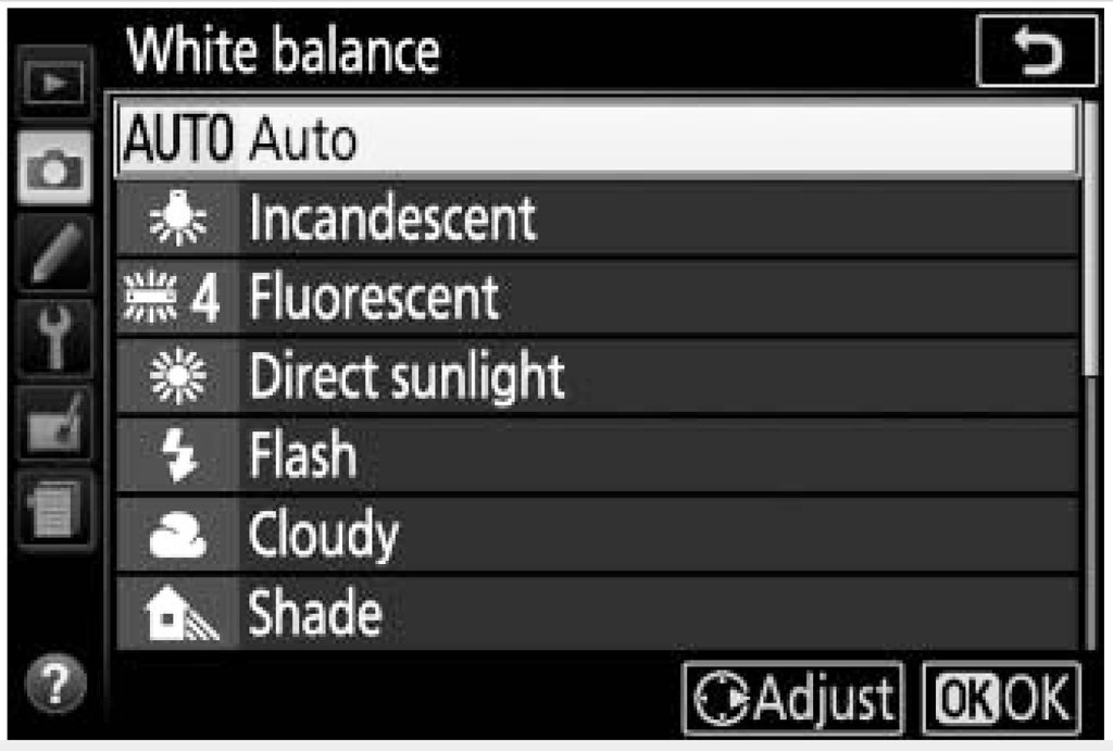
Here are some examples of white balance options and their effect under the same lighting conditions. First, here is the white balance menu in the camera. The idea is to select the option closest to the type of light you are using. This will change the way the camera processes the colors to try to produce a realistic color. There is another option scrolled off the bottom of the screen, CUSTOM WHITE BALANCE. For this option you place a white card in front of the lens, close enough that nothing else is visible in the picture. Then you take a shot of the card to set the proper color correction for the light being used. The camera will also let you use an existing photo for the white reference. Direct sunlight is the "standard" white light. While the different White Balance selections usually work to create reasonably good colors, not all lights of the same type (incandescent or fluorescent) produce the same color light, so at best you get an approximation of the color. Here are four pictures taken under an incandescent light bulb, using different white balance settings. The background was a white towel. The Incandescent White Balance picture is pretty true to the actual colors, and the towel does look "white." Auto White Balance is also pretty close but the towel has a bit of color. The Auto setting samples all the pixels in the image, looking for what it thinks is white (the lightest objects in the picture). But if you have large bright pale colored areas in the picture the camera may choose one of these as it's "white" reference and all bets are off as to what actual "white" things may look like in the photos! The Custom White Balance gave the best results. The towel is a better "white" that the previous two pictures. By comparison, the first two appear to have a somewhat pinkish towel on some monitors and my laptop. When in doubt use the Custom option and set your camera for the actual light you are using. If you have multiple lights of different types you must use the Custom option. But be aware that shadows will be different colors for the different lights. If you have been shooting outside under direct sunlight and have your camera set for that and forget to change the white balance the colors under different lighting conditions may be very far off. Incandescent lights produce a reddish color and everything will be tinted toward the red. Fluorescent lights are bluish or greenish, and everything will be colored in those shades. And "white" LEDs can be almost any tint (they are usually composed of red, green and blue LEDs all on at the same time. If you are shooting outdoors there are other considerations to remember. While we think of direct sunlight on a clear day as the "standard" many people forget that the largest outdoor light is that big blue thing called the "sky" that stretches from horizon to horizon. Anything that is not directly illuminated by the sun (shadows) will be shaded blue. Everything photographed in shaded areas will be blue. Back in film camera days we carried a "Skylight" filter (pale rose colored) to correct for the blue light from the sky. With digital cameras we need to remember to change the white balance to "Shade." The best overall lighting is on cloudy bright days. Water vapor tends to scatter sunlight nicely, producing large fuzzy white lights called clouds. Furthermore, the lighting is almost the same from all directions, producing true colors in shaded areas. In the studio photographers use bounce lights off of umbrellas, screens or just white ceilings to create this effect indoors. **** Having said all of this I feel the need to say many people do not have an understanding of the physiology of color. When I was about five years old I realized that I see different colors in different eyes. Everything in my left eye is slightly bluish tinted, while my right eye tints everything slightly red. I have had color blindness tests and I can see all colors with both eyes. I just see two of all colors. Actually, in film camera days, my right eye served as a built in Skylight filter to show me what pictures would look like if I used a Skylight filter on the camera! Alas, with digital cameras things are no longer that simple. By the time I was seven or eight I had read the encyclopedia to learn about light, and my Mother's medical texts to learn how the eyes and brain work. Since both eyes are seeing the same spectrum, I realized that one eye had to be "wrong." Then I realized that, in fact, both eyes could be "wrong" (whatever that means). And then it occurred to me I have no idea what other people are actually seeing. When I see something that I call "red" you may actually be sensing what I would call "green." But since we have both been taught to call whatever color we are seeing "red," we both look at the same thing is say it has the same color "red." But who knows what anyone else is actually seeing? Throw in the fact that no two computer or cell phone screens produce the same colors, and the same is true if we print our pictures on different printers, you have to stop and ask just what "the right color" means? When I say something is red, the Admiral corrects me and says "No, dear, that is orange." So pardon me if I am laughing out loud when someone goes on about getting "true colors" in photographs.


-
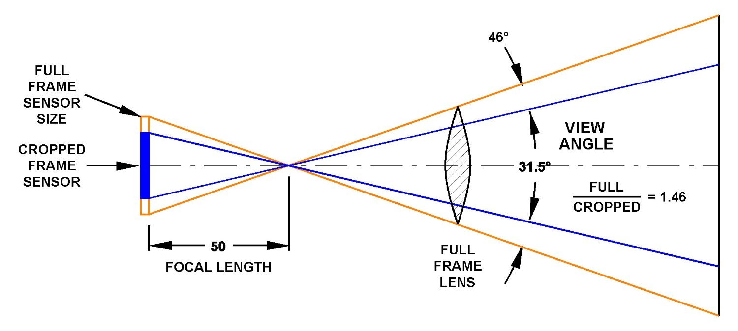
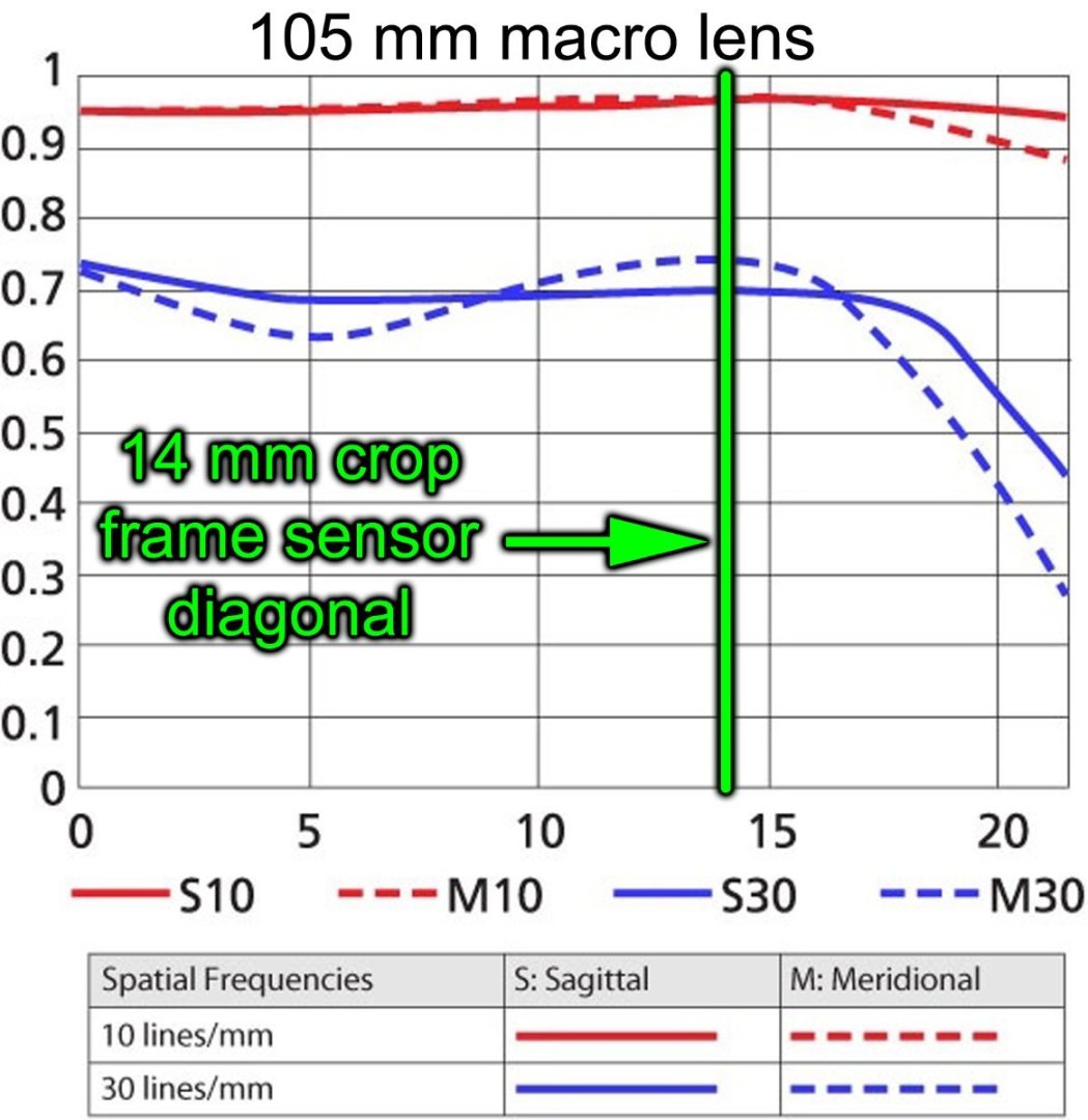
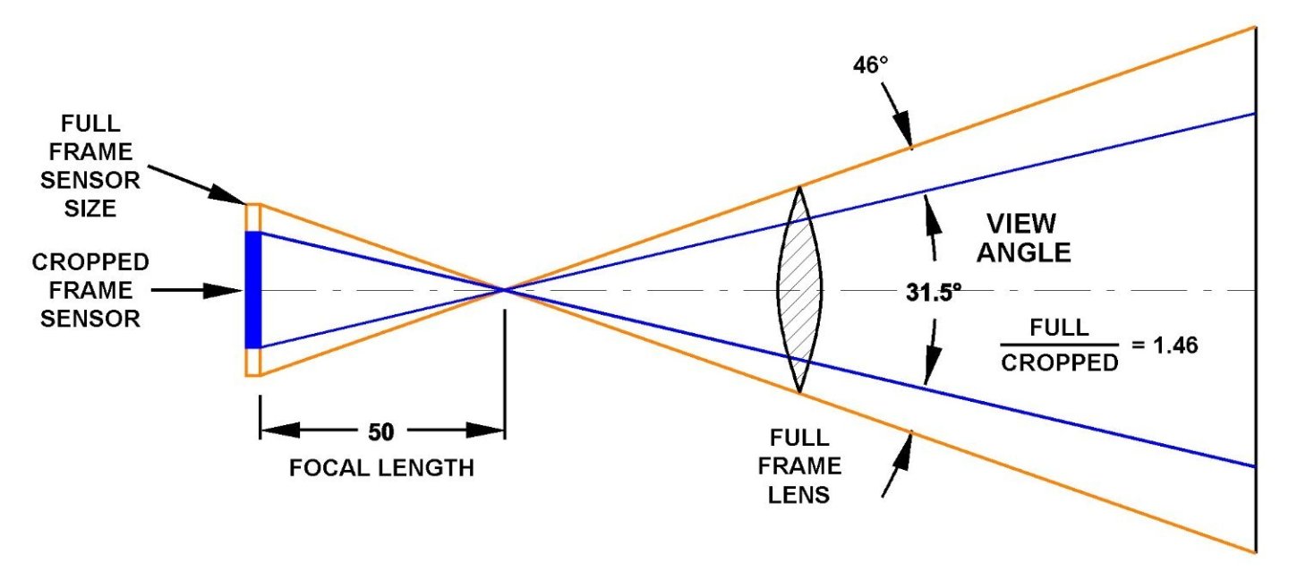
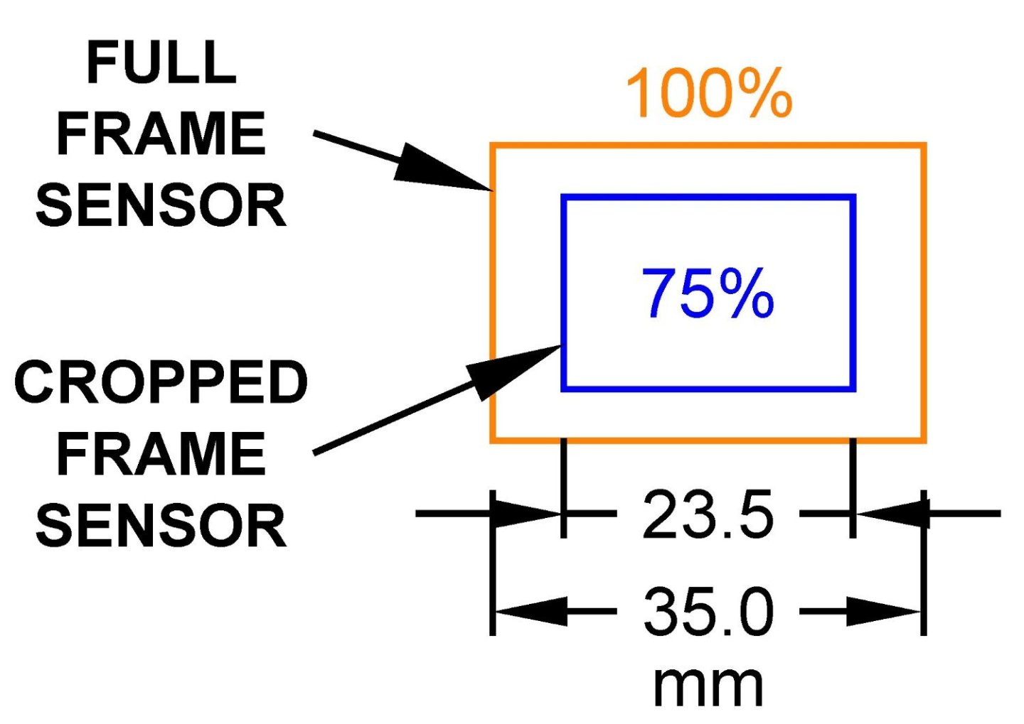
I was using the Nikon AF-S Micro Nikkor 105mm 1:2.8 G ED macro lens. The highest f stop in the focus distance window is f/32, but the lens runs out beyond this mark quite a bit. The camera (Nikon D5600) records the f stop as f/40 when I run it out. As VTHoikEE says the actual f stop is the result of a combination of things. I was focusing in to almost the minimum focus distance for the lens (12"/65mm from the focal plane, or about 5 1/2"/140 mm in front of the lens). The D5600 camera is a "DX" series body with a crop frame sensor 75% the size of a full frame sensor (35mm film frame size) and the lens is a full-frame ("FX" series) lens. Note: Not all crop frame sensors are 75% as large as a full frame sensor. This varies with manufacturer. The result is a narrower view angle and an effective focal length of 1.5 x 105 = 157.5 mm. This screws with all of the lens characteristics calculations and is probably why the camera reports it as f/40 in this photo. I have seen f/44 in some pictures shot close up at 1:1 image size on the sensor and that is about 1.5 x 32 = 48. **** Using the full frame lens on the crop frame body has several advantages. First the effective focal length is 1.5 times the full frame focal length (an advantage with telephoto lenses, but a disadvantage with wide angle lenses). The light intensity focused on the focal plane is the same in both the FX and DX cameras so there is no light loss as with a doubler between the lens and camera (and no loss of image resolution). The lens is smaller, lighter weight and less expensive than an equal focal length full frame lens. For example, I have a Nikon 200-500mm f/5.6 FX zoom lens that cost $1200 new a few years ago. On the DX camera body it is a 300-750mm focal length lens. A Nikon 800mm f/5.6 FX lens cost $16,300 at that time! But perhaps the greatest advantage is that you get overall sharper photos. With any lens the distortion increases from the center of the image to the corners. The FX lenses cast a 22mm diameter image, with blur and chromatic aberration greatest at the greatest radius (the corners of the image). If you look at the resolution graph for the 105mm macro lens the worst distortion is out beyond 16mm (left, the vertical axis is resolution with 1 being perfect, and the horizontal axis is mm from the center of the image). But the DX sensor maximum radius is 14mm. So the crop frame sensor crops out the most distorted parts of the image. The result is that the crop frame sensor camera with a full frame lens produces sharper overall images than the full frame camera with a full frame lens.
-
Second law of thermodynamics. Entropy increases with everything that happens. And the writing of men is no less susceptible than the finest works of art. Not even the words of poets.
-
Allan, There are a few reviews on line and most seem to like this product. But they agree that it will run down the AA cells pretty quickly. That isn't surprising - it really is pretty bright. I usually don't leave the lights on all the time anyway when I am setting up for pictures. But spare AA cells would be a good idea, especially it you are in the field! Some reviews recommend the lithium battery (US$49.00) and say it lasts much longer. As with any other new toy I will be experimenting with this. You can always take the light off the camera and hold it to the side to get shadow effects.
-
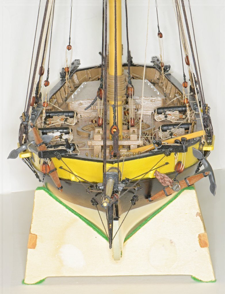
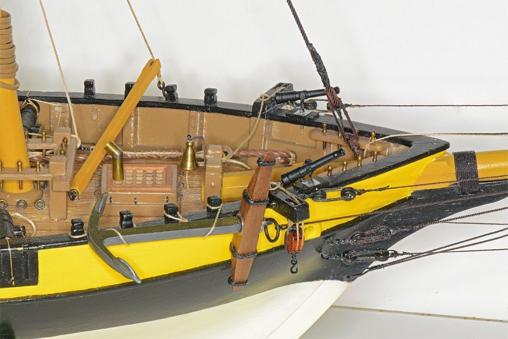
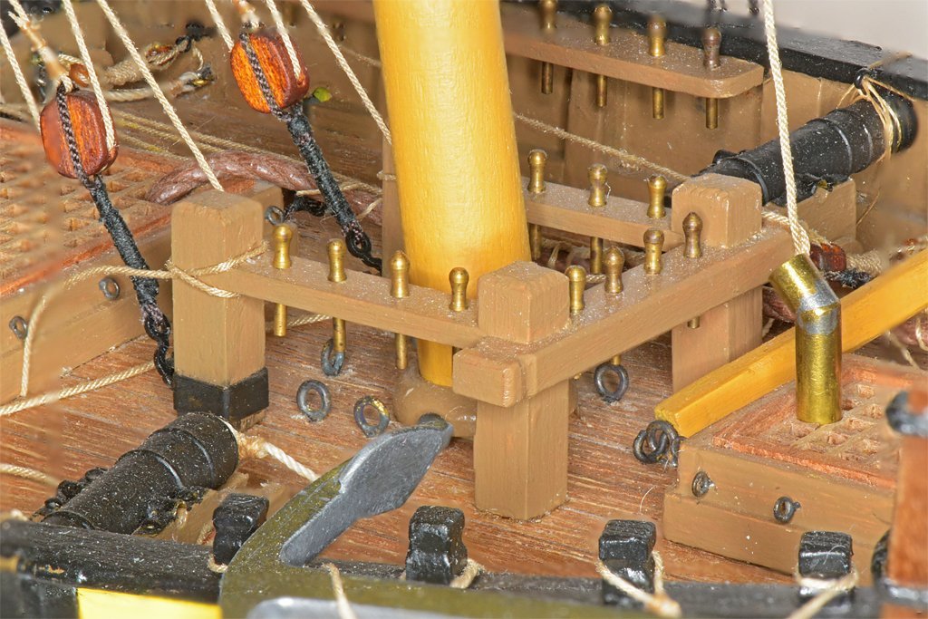
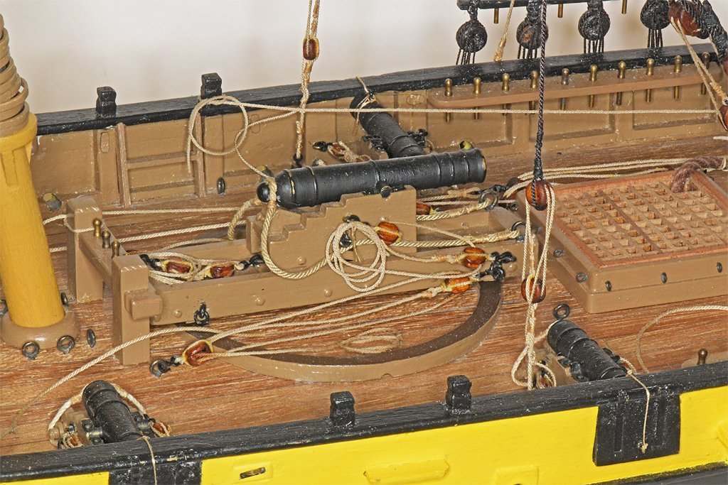
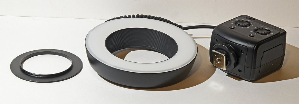
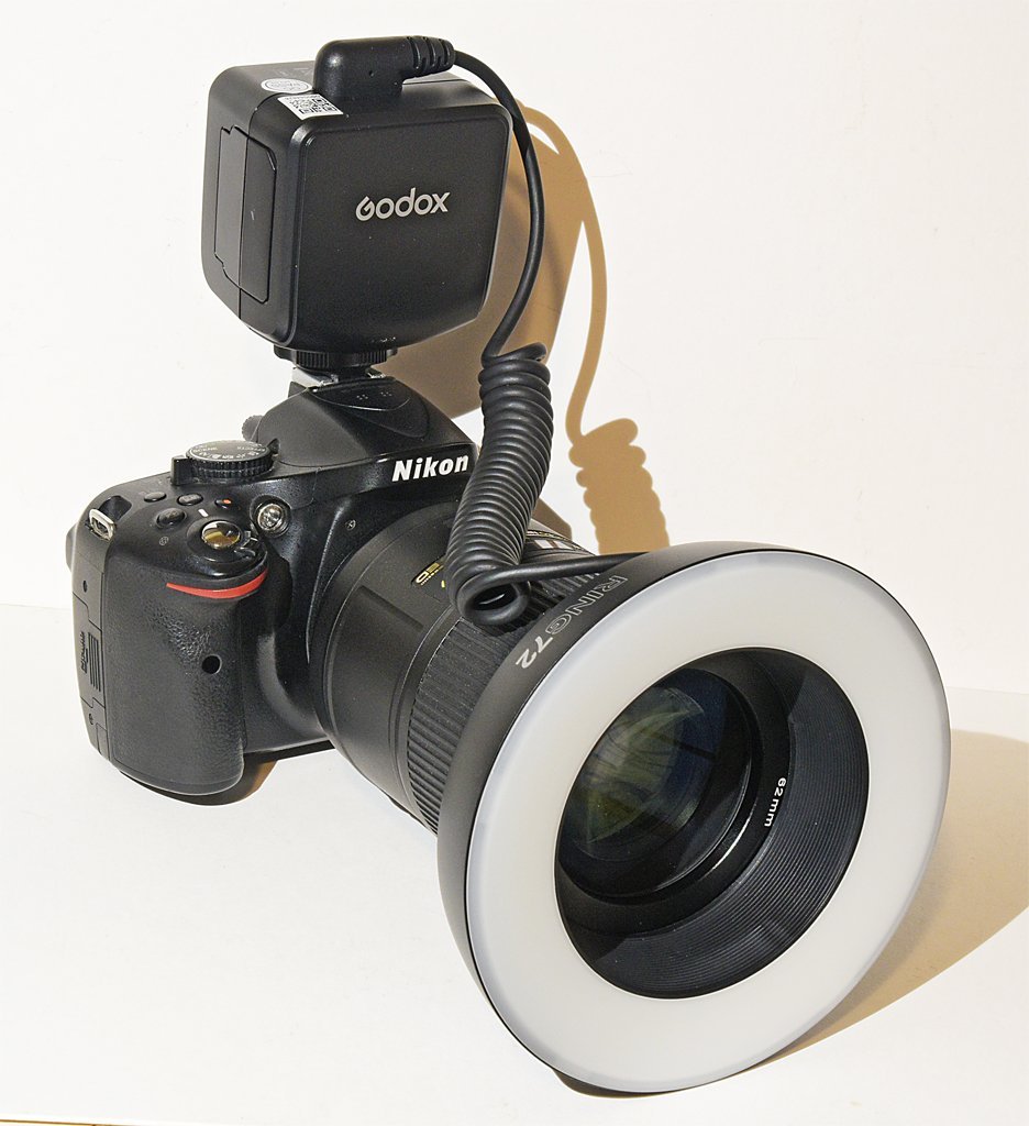
Note: This is not a product endorsement, and I have no connection to anyone selling this product. I just got one and have no idea how long it will last. I do a fair amount of macro photography and close up photography. Lighting is always a problem. I have been using everything from sunlight coming in the window to various desk lamps and such. Each required a different white balance and low light intensity and harsh shadows were always a problem. I have seen several "professional" (synonym = high price) units but never wanted to spend hundreds of dollars on one. I recently found a relatively low cost unit at a local camera store and decided to give it a try. It is a Godox Ring 72 and it cost US$75.00. The "72" refers to 72 white LEDs in the assembly. It runs on four AA cells. They also offer a rechargeable lithium battery which I do not have. There are three parts to the unit. The ring light is connected to the controller with a coiled cord. A metal adapter ring screws into the filter threads on the front of the lens. The unit comes with eight adapter rings for 49, 52, 55, 58, 62, 67, 72 and 77mm filter threads. After the adapter ring is attached to the lens the ring light just slips in place over the ring. The controller has a "cold shoe" that fits into the camera's flash unit "hot shoe" - but the ring light adapter has no electrical connection to the camera. The controller does not have to be attached to the camera, but it is very convenient to have it right in front of you. One interesting feature is that the light is divided into two banks (left and right) of 36 LEDs each. Each side can be turned on/off independently. Also, each side has a dimmer in 10 increments so you can create shadows and control light intensity. I haven't experimented with this yet, and I can see from the photos below that this may be a useful way to create shadows in closeup pictures. Here is a sample photo. This is a photo stacked image from eleven shots. The first thing I noticed is the light is very bright, so I was shooting at f/40 and 1/16 second with ISO 640! In the past I have been using something like f/8 and 1/30 second at ISO 640. I always had problems with Photoshop photo stacking when I used the wider apertures (shorter focal distances). The program had trouble determining where the edges of things like ropes were, and left a blur on either side where it chose the wrong out of focus photo. This required a LOT of editing to correct! The photo above had no editing! If you look very closely you might see a couple of places with background blur along the ropes, but if I hadn't mentioned it I'll bet you would never notice. All in all, this is a much clearer image than any I have gotten before with photo stacking. Also, you can clearly see the dust accumulation over the past few weeks when I have been working on sails and a lot of non-modelling projects! This next photo is even better! This is just three images photo stacked, with no further editing. In the past I would have used at least eight shots for this picture. It was shot at f/36 and 1 second and ISO 640. In fact, the middle photo that was focused on the bell has no noticeable blurring near or far unless you blow up the image, and then it is only slightly out of focus at the bulwark caps. With the bright light and very small apertures the depth of field in each image is about as great as the width of the model. Here is another extreme photo stacking example, using nine photos. The over all depth of the model is about 27 1/2 inches (about 700 mm). In the past I used 12 photos and there were a number of blurry places. The picture also shows that the jib boom is a bit misaligned to the starboard side (left in the photo). Shortly after rigging the bowsprit and bib boom I accidentally caught my shirtsleeve on the bowsprit and broke the freshly rigged port stay! Looks like when I re-rigged it I didn't pull it tight enough to pull the jib boom back in line. This photo does show one shortcoming of the ring light. All surfaces perpendicular to the line of sight have a lot of glare where the light is reflected back. Another problem is the lack of control of the light angle to create shadows. Maybe adjusting the relative brightness of the two banks of lights can be used to create some shadow effects - for further experimentation. This thing is new, and I have no idea how long it will last. But it was relatively inexpensive and worth trying. It is much brighter than the lights I have been using so it does allow better depth of field in the pictures. The light output is said to be 8 Watts and 5600 Kelvin (daylight color). It weighs 245 grams without batteries. Here is one more picture made from five photo stacked images shot at f/36, 1/16 second and ISO 640. Notice the very soft blurred shadows on the background. This is a lot less distracting than harsh shadows from a single distant point light.
-
Laptop recommendations?
Dr PR replied to Mike Shea's topic in CAD and 3D Modelling/Drafting Plans with Software
Here are a few more comments. 1. What CAD program do you want to use? What operating system does it run on? Get a machine that is compatible with the software. 2. Multi tasking. I have an old (2013) 3,4 GHz 6 core i7 and Windows will run 12 simultaneous tasks on these. I have seen all 6 cores running 100%, primarily for a single program, and generating a LOT of heat! So multiple cores are used. My CAD program (DesignCAD 3D Max) originated before multiple cores became common. But when it is running it does use multiple cores. Although the main CAD code may run on just one core at a time, it constantly calls other Windows library routines and they use different cores. The operating system is running on a core, and background tasks like checking for email and such run on separate cores. It is not unusual to see all six cores operating while the CAD program is running. 3. For high performance CAD rendering (even simple shading and shadows) you need a graphics card that supports OPEN GL and has as many Graphic Processor Units (GPUs) as possible. I strongly recommend nVidia graphics cards - they have been a leader in CAD graphics for decades. You must install the OPEN GL drivers in the operating system to achieve high performance. 4. Get the highest bus speed RAM that is compatible with your CPU. Even the highest speed RAM is much slower than the internal CPU data buss. With each memory access there is a relatively long (from the CPU's standpoint) wait period while the RAM access the memory location. Faster RAM means fewer wait states for the processor while the RAM reads or writes the data. Many mother boards offer two RAM configurations - straight 64 Mbyte or interleaved 32 Mbyte. With straight 64 MByte memory each read/write involves a) setting up the address, b) beginning the access, c) waiting for the RAM to access the data and d) transferring the data. Then the next RAM access (a) begins. The interleaved RAM operates faster because while data is being written/red from one bank (c, d) the other bank is starting access for the next data (a, b). CAUTION: Do not fall for the marketing hype about RAM speed! RAM modules have on-board processors that can talk to the BIOS (very lo level part of the operating system) to tell how fast the memory can operate. This allows the machine to adjust internal settings to get the high speeds. BUT Some RAM can operate at the advertised speed at the normal system operating voltages. But if you increase the voltages RAM generally runs faster. So some RAM sticks will try to jack up the voltages. This has two effects. First it increases heat in the system, and that can cause the processor to slow down - no net gain. Worse still, some RAM will try to increase bus voltages above the maximum for the processor, and that fries the processor and/or the bus controller. $$$$ up in smoke! This used to be a problem when marketing scum advertised their low performance (at normal voltages) junk as higher speed than actually rated. Read the reviews and chose the RAM and CPU carefully.