Dr PR
-
Posts
2,471 -
Joined
-
Last visited
Content Type
Profiles
Forums
Gallery
Events
Everything posted by Dr PR
-
Mark, The sheave could be used for the flag halyard. In some cases the halyard ran though a small "jewel" block hanging from the end of the gaff. Either way would work. I have seen examples where the ends of the flag halyard was belayed to a cleat on the boom. This way the lines moved with the boom and gaff. You really can't tie them off to anything else (like the bulwarks). On schooners that flew gaff topsails the topsail sheet sometimes ran through a sheave at the end of the gaff. Maybe the model plans just copied the gaff drawing from a schooner. On square riggers it was not common to have a gaff topsail above the spanker/driver. However, I have seen at least one instance where a gaff topsail was used on the mizzen above the spanker. Sometimes such additional sails were rigged in light winds but not normally flown.
-
 Rob, Very nice work! For me making a bunch of tiny complicated parts like this is like banging my head against the wall - because it is so nice when it stops.
 -
Welcome! If you are going to build a grand banks fishing schooner I strongly recommend getting Howard Chapelle's The American Fishing Schooners 1825-193 (W. W. Norton & Company, New York and London, 1971). It has an amazing amount of information about these vessels and a 370 page "Notebook" (Appendix) with drawings and details from real fishing schooners. It will help you understand how these boats were built and rigged.
-
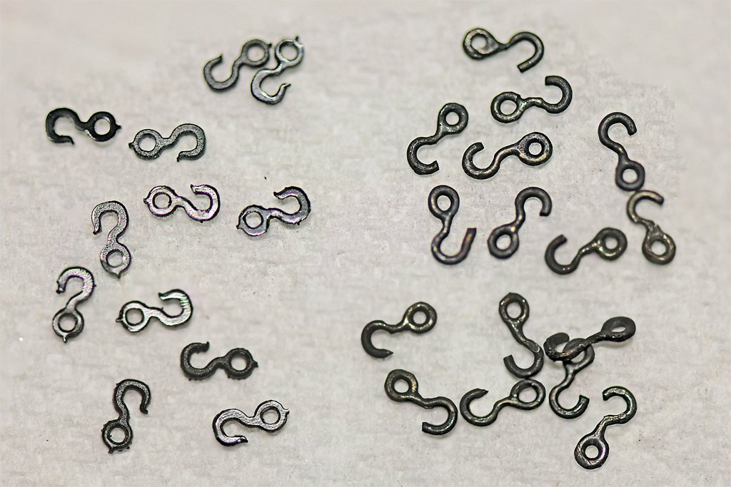
I have been ordering supplies for my next build, the USS Cape MSI-2, and planning my next moves on the Albatros. Before continuing with the rigging I need to clean up some loose ends (literally) on the deck. I have belayed a few lines but I need to add the rope loops. While fiddling with some of these I broke a hook on the static lines positioning the pivot gun. I just bumped the cannon barrel and pop! one of the hooks broke. I have broken a couple other hooks while assembling the model, and this has made me rethink what I want to use for the rest of the rigging. I have been using the Syren plastic hooks (left in the photo). These are the 4mm hooks, and I am also using a few 3mm and 5mm hooks. They look good and are a uniform size. But I don't want to have to be replacing broken hooks after I have a lot of the lines already in place. I decided to make some hooks from brass wire (right in the photo). I used 0.024 inch (0.6 mm) wire and formed it around drill bits that were the same diameter as the openings in the Syren hooks. The loops were soldered closed and then they were blackened with Brass Black. I was trying to make 4mm hooks, but as you can see my hooks are not as uniform as the Syren parts. Some look more like 5mm hooks. I will use the metal parts as insurance against broken hooks. The model won't have a lot of hooks side by side in any place, so slight size differences won't matter.
-
Very nice. I find the nibbing to be relaxing and fun!
-
Mark, We may be laughing, but not at you. We are recalling the frustration we all had when in the same situation. When it comes to rigging, few authors ever agree on anything! There were possibly as many ways to rig a ship as there were vessels! The gaff sail outhaul is often rigged similar to what you show in your drawing. One variation I have seen is for the forward block to be attached to the boom jaws instead of the mast. But otherwise the operation of the tackle is the same. The one rule for rigging is that lines must not foul each other, and should run free without chafing on other lines or spars. Generally, lines that originate lower on the mast and yards belay forward, and lines from higher up belay aft. Lines that originate on the mast or from points/blocks close to the mast belay around the base of the mast (fife rails). Lines that originate out near the ends of yards usually belay on the bulwarks (pin rails or cleats). An exception on ships with many topsails, topgallants and royals will see the lines for these sails that originate near the masts lead outboard through fairleads on the shrouds to belay on the bulwarks/pin rails. A very good reference for rigging is Darcy Lever's The Young Sea Officer's Sheet Anchor (1808).
-
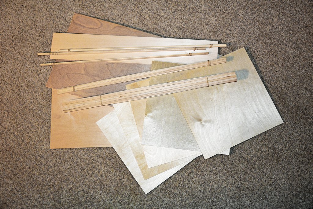
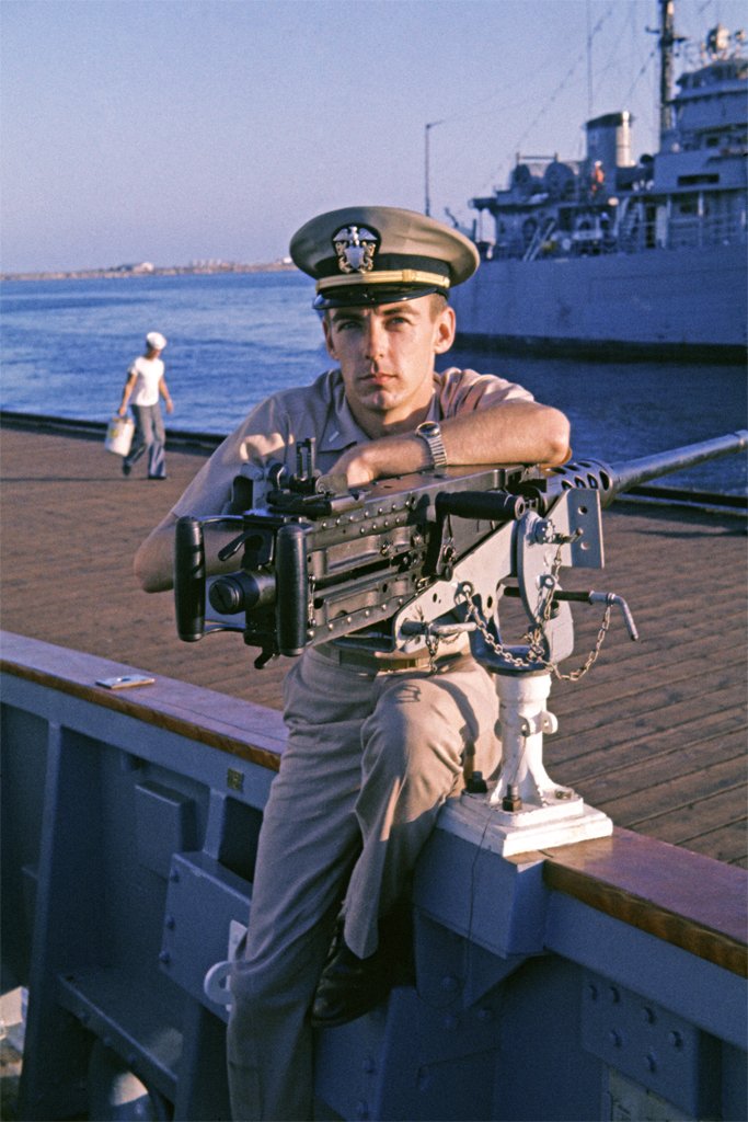
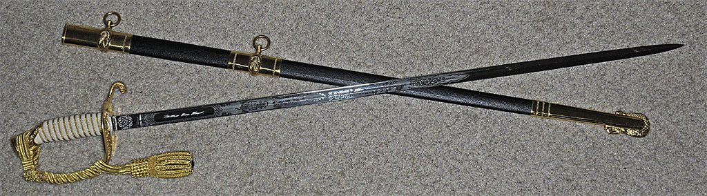
Mark, I am glad you enjoy the tales. I have been collecting materials for the build. Here is a photo of wood for a do-it-yourself MSI kit. I will be using 1/8 inch (3.18 mm), 1/16 inch (1.59 mm), 1/32 inch (0.79 mm) and 1/64 inch (0.40 mm) plywood for the hull bulkheads, center frame (keel), and the superstructure bulkheads. Much of the original superstructure was constructed of 3/4 inch (19 mm) marine plywood. There are 60 1/16 x 1/6 inch (1.59 x 1.59 mm) basswood sticks for the deck planking and 80 1/16 x 3/16 inch (1.59 x 4.76 mm) basswood sticks for the hull planking. A 4 inch x 1/16 inch (101.6 x 1.59 mm) basswood sheet will provide the planksheers, nibbing/margin boards, equipment foundations and other irregular pieces. I have some 1/8 x 1/8 inch (3.18 x 3.18 mm) basswood sticks to serve as internal support for the deckhouse bulkheads. There are a few sticks of various sizes for the bilge keels and rub rails around the deck edge. The winches and minesweeping machinery will be made of brass mostly. I have a stock on hand, but will also try to acquire more as I go along. The "pigs" (minesweeping floats), acoustic sounder and details like bitts and chocks may be 3D printed. However, I am not enamored with 3D printing, so I may decide to make these things out of more traditional materials. **** Here is a little more about the Cape and minesweeping. Here is a very young Ensign Hays fresh out of Officer Candidate School leaning on the Cape's main armament - a M2 Browning .50 caliber machine gun - attempting to look like a fierce warrior. The machine gun wasn't provided to repel boarders or attack other vessels, although it could be used for that if war ever came to Long Beach. Minesweepers operated in formations. I included a photo in post #28 above of minesweepers in formation. The first ship (the Cape in this picture) spread sweep gear to both sides. A cable rigged between the ship and the pigs (floats) was fitted with cable cutters to slice the mooring cables for moored mines. The following vessels lined up to one side or the other, with their bows following the pig of the ship ahead, and streamed sweeps to that side only. This produced a wide sweep pattern with each run through a mine field. Each ship was protected by the sweeps of the ships ahead - except the lead ship. If a ship did cut free a mine it popped to the surface ahead of the following ship. It was a threat to all the other minesweepers following in the formation. This is where the machine gun came in. It was mounted on the bulwark near the bow. When a mine popped up ahead we opened fire with the machine gun to try to detonate it. Minesweepers typically had a relatively high superstructure forward. Lookouts were posted on top of the pilot house to search for any mines visible in the water or those that were cut free by leading ships. A couple of fellows had M1 Garand rifles and I was stationed there with a BAR (Browning Automatic Rifle). If we saw a mine we opened fire primarily to mark the position for the machine gun crew, and maybe blow up the mine before the machine gun got it. This was a "high pucker factor" operation. Mines were designed to sink large ships like battleships and aircraft carriers. Minesweepers were tiny by comparison, and if they hit a mine they could be blown to splinters in an instant. We occasionally practiced target shooting using 50 gallon barrels as target "mines." The machine gun had a semi-automatic mode where you could fire one shot at a time. This let you see where the bullets hit after you took aim. In fully automatic mode these guns just sprayed a bunch of bullets in an elliptical path all around the target and you really couldn't get a good idea how to aim the gun. I also had my own Colt M1911 .45 caliber pistol. I am not really sure why and I never fired it while on the Cape. However, I had to qualify with the .45 when I went aboard the Oklahoma City because I was a nuclear weapons courier, classified document courier and payroll courier. And I had my trusty sword that officers were required to buy. I did use it occasionally in fancy full dress uniform for change of command ceremonies and such. But we were never boarded by pirates or pleasure boaters.
- 492 replies
-
- 14
-

-

-
- minesweeper
- Cape
- (and 1 more)
-
Are there better tools for drilling tiny holes?
Dr PR replied to Dan Poirier's topic in Modeling tools and Workshop Equipment
I second that Toolmaker said - the tungsten carbide bits are VERY fragile and break if they are slightly bent. You cannot se the smallest bits in hand held tools - at least not for very long. And if they break off flush with the surface you eitherr leave them in place - blocking the hole you are trying to drill = or dig them out leaving behind a crater. High speed steel is what you want for pin vices and other hand tools. I have used the "aluminum wrap" technique with pin vices with collets that do not close entirely. It works sometimes, sometimes not. I am not entirely certain I got the four "machinists'" pin vices from Micromark - I am sure they are made in China and they seem to be available from many sources on the Internet. The smallest holds a #80 drill bit very firmly with the collet tightened hand tight (no tools needed). The entire shaft is hollow so very long drill bits can be used with the larger devices. And to steady your drilling in tight places you can insert a wooden dowel in the back end to fix the axis of rotation. I have used this method to drill holes in the inner side of bulwarks from across the model and through standing rigging. A good source for tools and materials is McMaster-Carr. We used the for decades at work. Good quality tools and materials. They sell small quantities to hobbyists. https://www.mcmaster.com/ -
Are there better tools for drilling tiny holes?
Dr PR replied to Dan Poirier's topic in Modeling tools and Workshop Equipment
I bought a set of four machinists" pin vices with collets from Micro Mark with the smallest closing down to essentially nothing. It holds the smallest drill bits I have found. These "pin vices" do not have a "head" so they can be fit into collets in a milling machine. How true they are for use a a drill press or milling machine I do not know. But they work fine for hand tools. I have been satisfied with them for hand use. 4-piece Machinist's Pin Vise Set $18.95 https://micromark.com/products/4-piece-machinists-pin-vise-set-1?variant=44018022318251&frt=15&gad_source=1&gclid=EAIaIQobChMI8OO3pNDBiAMVEw2tBh1YPjleEAQYASABEgL1jPD_BwE -
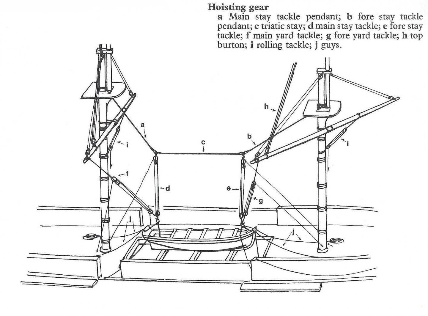
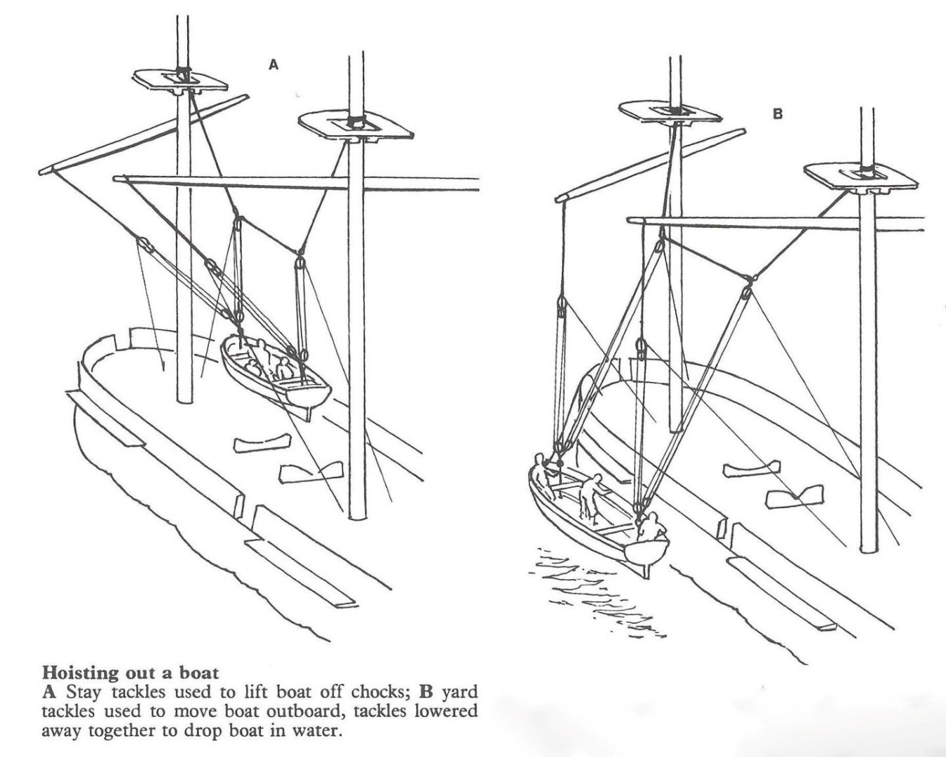
Here are two images that illustrate the yard and stay tackle operation to launch a boat (I don't recall where these illustrations came from). Here is the detailed rigging: Note that there are eight tackles for lifting and moving the boat, and four guys to control it while it is moving. The top burton and rolling tackles keep the yard horizontal. They all have to be handled in coordination. One capstan isn't enough. All of the falls would have been handled by teams of sailors. Here is the process: The stay tackles lift the boat from its cradle. The yard tackles haul it outboard. Then the yard tackles are let out to lower the boat, while the stay tackles are slacked so as to not interfere. Bringing the boat back on board is the reverse of this process. The distance between the stay tackles is varied by setting the length of the triatic stay, longer for longer boats and shorter for smaller boats. The lower block of one stay tackle can be hooked to the upper block of the other to make a rig with just the second tackle lifting while the first moves the rig fore and aft between the masts. Adding a yard tackle hooked to the object being lifted allows using the rig to move objects around on deck, fore and aft and side to side. This type of rig was used to move cannon and other large objects. Just about every imaginable combination of these basic tackles could be hooked together to handle whatever needed to be moved. Anchors were fished up to the rail with the fore stay or burton tackles, and could be moved back to positions farther aft with the yard tackles. A winch or capstan could be used for these operations using only one lifting tackle at a time.
- 27 replies
-
- 13
-
-

-

-
- capstan
- small boats
- (and 1 more)
-
Art supply stores sometimes have ponce wheels. Also check model railroading supply places.
-
Very nice. I see there is some personal history there.
-
Still here. I have been working out the supplies needed for my next model, the USS Cape MSI-2, and that has taken a bit of time. It is summer, and time for outdoor activities. Now I must do the taxes for a non-profit (I am the Treasurer). Then I hope to get back to the Albatros and finish the sails and start the rigging.
-
Planking Method Name
Dr PR replied to Thukydides's topic in Building, Framing, Planking and plating a ships hull and deck
How do you implement those scarf joints? Very carefully! -
John, This is a long shot, but you might find a patent for the winch in the US Patent Office archives. When I was working on the OK City model I found the patents for a couple of winches there, along with patents for the entire Talos missile launching system! Hundreds of drawings and detailed descriptions. Search for Biefort and winch - I think that is the name in the photo you show.
-
I love this build! You are so lucky to have the original vessel as a guide.
- 174 replies
-
- 2
-
-
- Vigilance
- Sailing Trawler
- (and 1 more)
-
John, Those are awfully skinny smoke pipes! But at least there are four of them. But why are they broken up into two or three sections like that?
-
Steve, Good progress! I like the new 12 pounder. Historical records tell that the pivot gun on these small revenue cutters was often a 12 pounder. The short range carronade would have been nearly useless. They were OK on ships that had dozens of them along with a battery of long guns, where the carronades were used in the final moments before boarding. But the revenue cutters with a single gun needed to have an effect at longer ranges. Before starting on the rigging you might want to read though this link:
-
Electroplating Britania metal at home - doable?
Dr PR replied to Wawona59's topic in Metal Work, Soldering and Metal Fittings
That makes two of us. And that is why it was so amazing to me! -
bdg, Thanks for the link. The 1:48 scale prop should be 1.4574 inch (37 mm). The Bluejacket 5 blade prop is 1.5 inch (38 mm) diameter. That is 0.0425 inch (about 3/64" or 1.08 mm) oversize. I could probably live with that. It looks like the part is cast metal, and it will need some cleanup. That would be an opportunity to reduce the blade length (prop radius) by 0.021 inch (0.5 mm). But the Bluejacket prop blades are not shaped like the MSI propeller blades. That would be more noticeable, and to keep with the tradition of the original, there should be nothing noteworthy about it. The Bluejacket part is only US$5.16. That is a LOT cheaper than all the hours and frustration needed to produce the STL file for the 3D printer. I'll try to make a 3D print of the propeller, but if that fails the Bluejacket part is a backup. **** Thanks to everyone for the likes. But believe it or not, I am not exaggerating! After six months of McHale's Navy I went to the flagship of the Seventh Fleet - the largest fleet in the world at that time. There were nearly 200 officers in the wardroom and a disconcertingly large number of flag officers (Admirals, Captains and Colonels) roaming about. The other JOs (junior officers) were curious about my background, and I told them that I was glad to be in the real navy. One of them, Ensign Clancy Omberg, rolled his eyes and said "This is the real navy?"
- 492 replies
-
- 5
-
-
- minesweeper
- Cape
- (and 1 more)
-
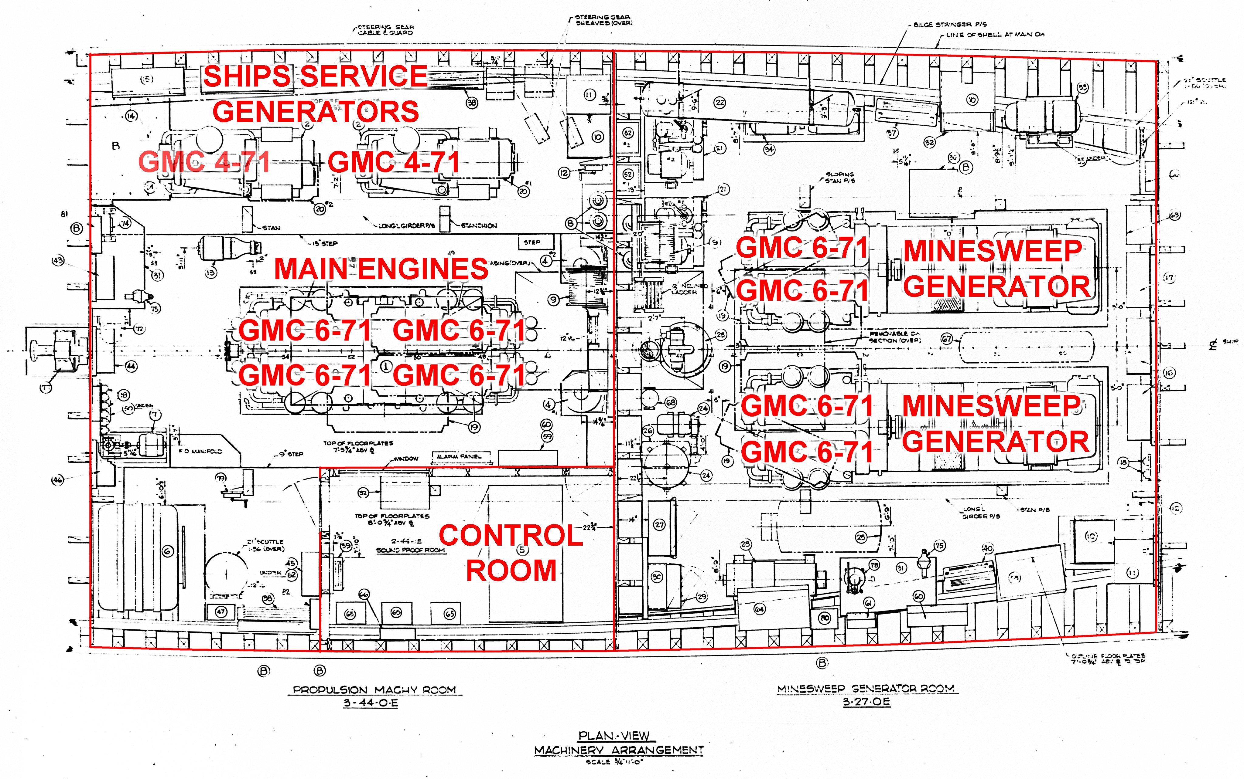
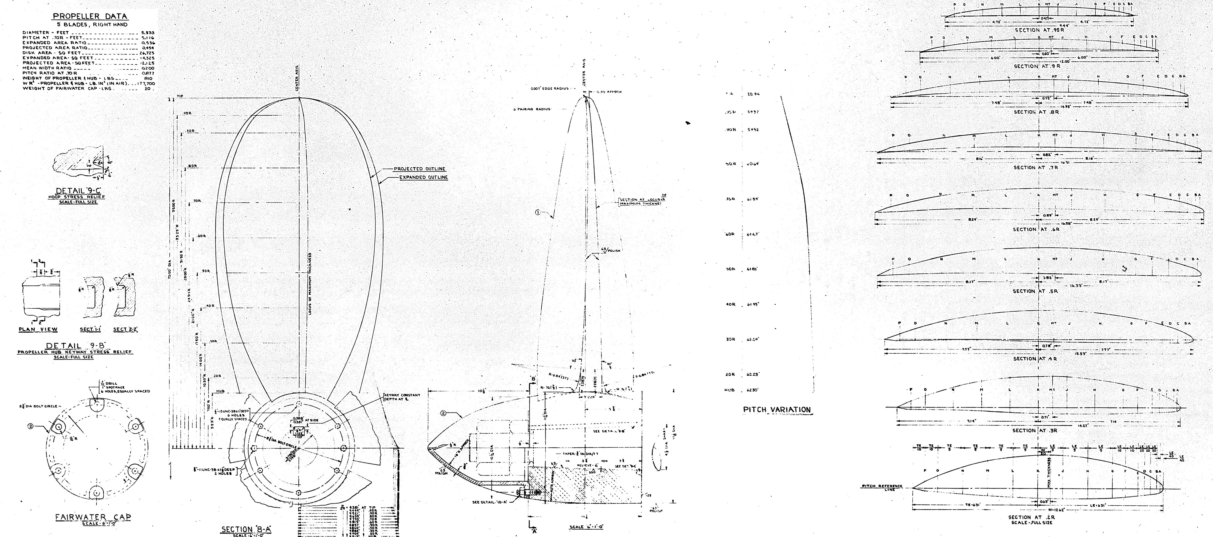
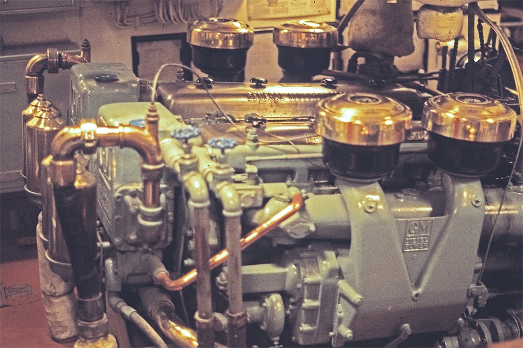
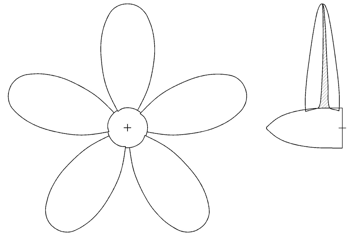
One of the challenges for this model will be the propeller. The MSIs had a five-bladed propeller and I will need one for the model. I don't have a machine shop and the necessary tools to tackle this problem like Keith Aug is doing on his Cangarda build. I have designed three-blade props for my future 1:96 USS Oklahoma City CLG-5 build, and printed them with a 3D resin printer, so I guess this will be how I make the prop for the Cape. The blueprint for the MSI propeller is marginally clear - not very good images on the microfilm. But it does have all the necessary information to allow an accurate 3D CAD model to be constructed. I don't look forward to this because stretching surfaces over the twisted outlines of the propeller blades is a tedious task. But I only have to make one and then copy it five times! Here is the propeller blueprint with all the gruesome details. This leads me into some details of the Cape's engineering plant - another reason the MSIs were "special." Hey, I was Engineering Officer and this was my "turf!" We had two engine rooms. The Forward Engine room contained two large minesweeping generators to produce power for the "magtail" magnetic mine sweep. It generated a large current through the salt water and this produced a large magnetic disturbance that triggered magnetic mines. Each generator was powered by two GMC 6-71 diesel engines. The After Engine Room had four more 225 hp GMC 6-71 diesels ganged together with 900 hp driving a single transmission connecting to the propeller shaft to turn the propeller. The transmission had a clutch and gearing for forward and reverse. This was a very uncommon arrangement. Also in this space were two GMC 4-71 diesels driving two Ships Service Generators that provided electricity for the ship. That is a lot of diesels. The "-71" meant a 71 cubic inch (1.16 liter) cylinder, and there were either 4 or 6 cylinders depending on the engines. So many of the parts were interchangeable. These were similar to ordinary GMC truck engines, with one major exception. Everything was non-magnetic! Specially made of fantastically expensive alloys! **** I have claimed the Cape was the smallest ship in the navy, but this might not have been totally true. Technically, the USS Cove MSI-1 was probably the shortest ship in the navy. The Cape and Cove were built from the same plans, but due to propulsion plant design shortcomings the Cove was perhaps a bit shorter. This 900 hp quad 6-71 diesel power plant drove a 36 foot (11 m) long 4.5 inch (114 mm) diameter propeller shaft and a 5.83 foot (1.78 m) diameter propeller. The propeller and prop shaft weighed 1374 pounds (623 kg), several times the mass of the crankshaft and pistons in the engines. When the ship needed to stop we couldn't just shift into reverse. The propeller "windmilled" as the ship moved forward. If we shifted to reverse suddenly the propeller would just turn the engines over backwards, and they were quite happy to run that way! So we first had to "stop shaft." To do this everyone in the engine room pulled on a lever that tightened a brake band around the prop shaft. This slowed the shaft and propeller and eventually brought them to a stop. Then we could shift into reverse and start slipping the clutch to turn the propeller in reverse. This took several minutes, and meanwhile the ship's momentum kept it moving forward, so rapid maneuvering wasn't possible. Add to this that the ship lost steerageway (the rudder stopped working) below 6 knots (and the speed limit in harbors was 5 knots), and the MSI's were about as maneuverable at low speeds as the Rock of Gibraltar. With mine sweep gear in the water, running at full throttle, the ships went wherever the currents took them. A consequence of all this was that early in the USS Cove's career it was maneuvering into a berth at the stern of a destroyer. The CO ordered all back (reverse) to check the ship's forward momentum and the engines stalled. The Cove continued forward and rammed into the stern of the destroyer, cutting a "V" shaped notch about a foot deep in the tin can's stern. In recognition of this event, the destroyer's officers presented the Cove with a plaque dedicated to the officers and men of the USS Canopener. The Cove may have been a bit shorter than the Cape as a result of that collision, and, therefore, actually the smallest ship in the navy. But because this episode brought the Cove to momentary fame (or notoriety), I claim the Cape was the least notable ship of the two.


- 492 replies
-
- 13
-
-
- minesweeper
- Cape
- (and 1 more)
-
Kieth, I don't know if the attached drawing will be of any help, but I was getting ready to post it on my USS Cape MSI-2 thread. The MSIs had five-bladed propellers. From the photo you posted I think the shape may not be exactly the same, but the drawing does have information about the pitch and thickness of the proportional thrust blades. If you need higher resolution I can probably supply that. Send me a PM. The prop in your photo looks to me to be a more modern design with a bit of curvature to the blades (as seen along the prop shaft axis. The Cangarda may have had straighter blades when she was originally built. Your technique is very clever and it let you use all sorts of the tools in your shop. I am totally green with envy! I will 3D print the prop for the MSI (not nearly as much fun as what you are doing).

-
Electroplating Britania metal at home - doable?
Dr PR replied to Wawona59's topic in Metal Work, Soldering and Metal Fittings
Valeriy gave some tips on electroplating in his Varyag post several years ago. He is an expert at this sort of thing. https://modelshipworld.com/topic/19333-varyag-1901-by-valeriy-v-finished-scale-175-russian-cruiser/?do=findComment&comment=590551 -
Cap San Diego by mikegr - 1/160
Dr PR replied to mikegr's topic in - Build logs for subjects built 1901 - Present Day
Thanks. -
Cap San Diego by mikegr - 1/160
Dr PR replied to mikegr's topic in - Build logs for subjects built 1901 - Present Day
What resin are you using now. Is it flexible when hardened?