
HOLIDAY DONATION DRIVE - SUPPORT MSW - DO YOUR PART TO KEEP THIS GREAT FORUM GOING! (89 donations so far out of 49,000 members - C'mon guys!)
×


Dr PR
-
Posts
2,445 -
Joined
-
Last visited
Content Type
Profiles
Forums
Gallery
Events
Everything posted by Dr PR
-
Second law of thermodynamics. Entropy increases with everything that happens. And the writing of men is no less susceptible than the finest works of art. Not even the words of poets.
-
Allan, There are a few reviews on line and most seem to like this product. But they agree that it will run down the AA cells pretty quickly. That isn't surprising - it really is pretty bright. I usually don't leave the lights on all the time anyway when I am setting up for pictures. But spare AA cells would be a good idea, especially it you are in the field! Some reviews recommend the lithium battery (US$49.00) and say it lasts much longer. As with any other new toy I will be experimenting with this. You can always take the light off the camera and hold it to the side to get shadow effects.
-
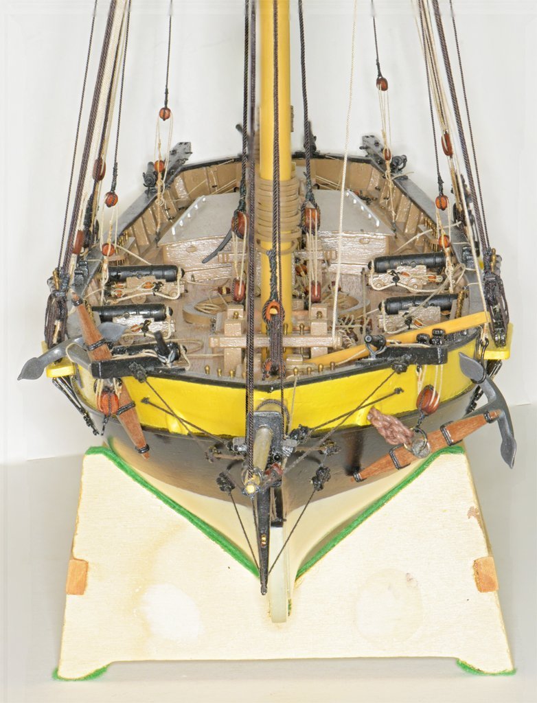
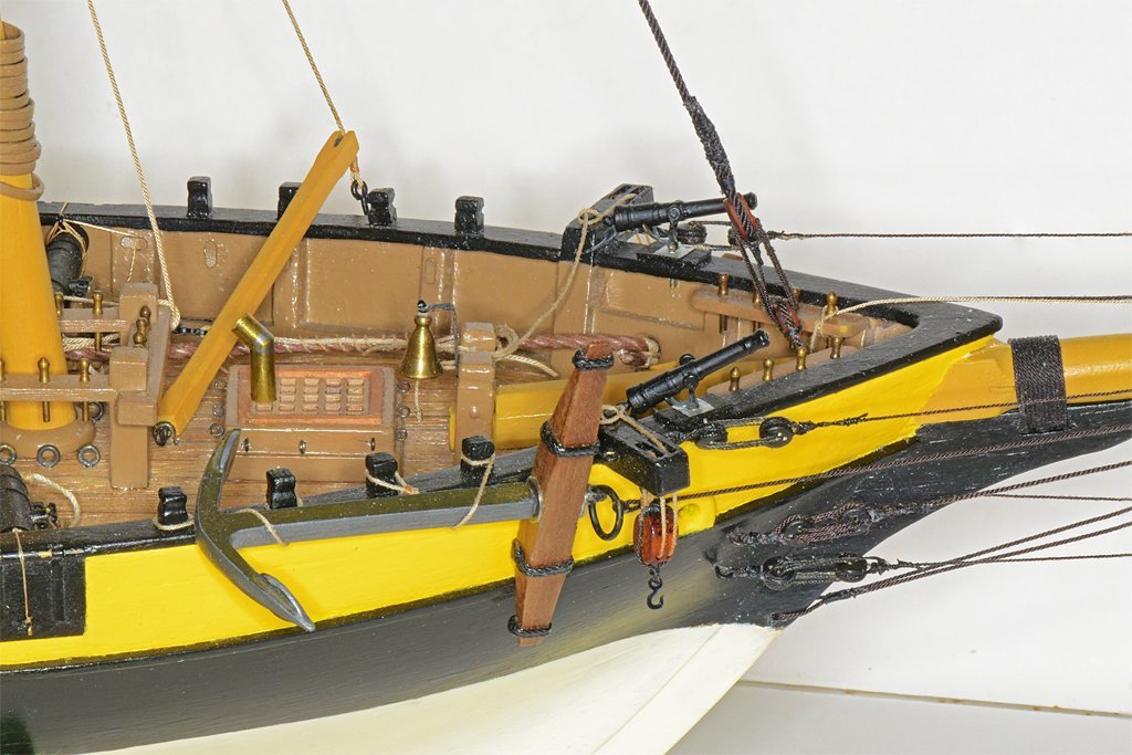
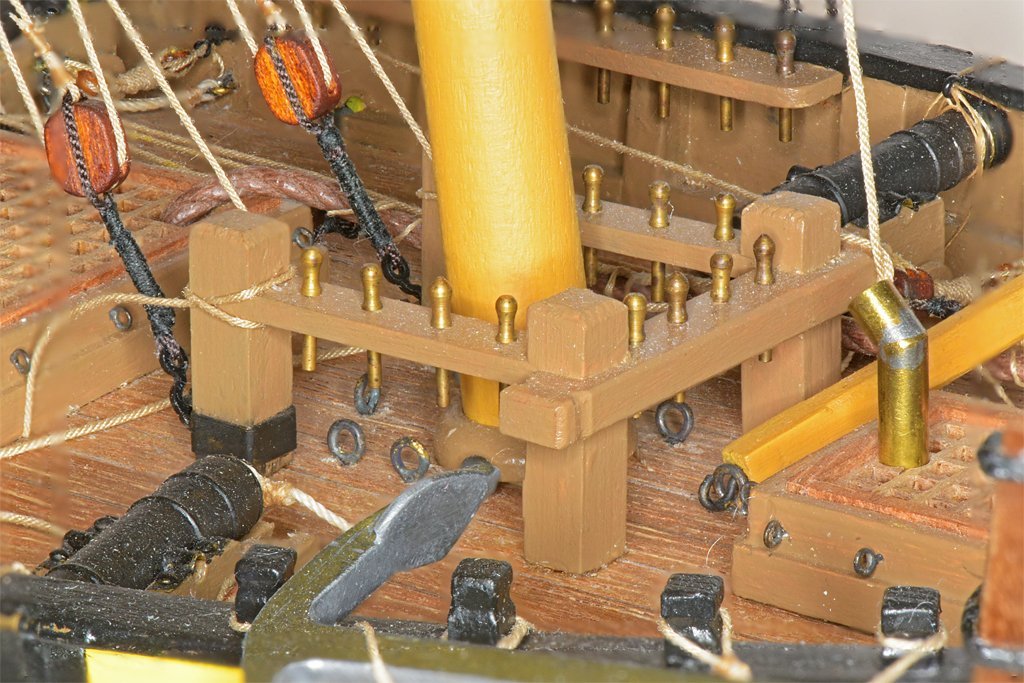
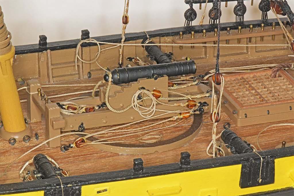
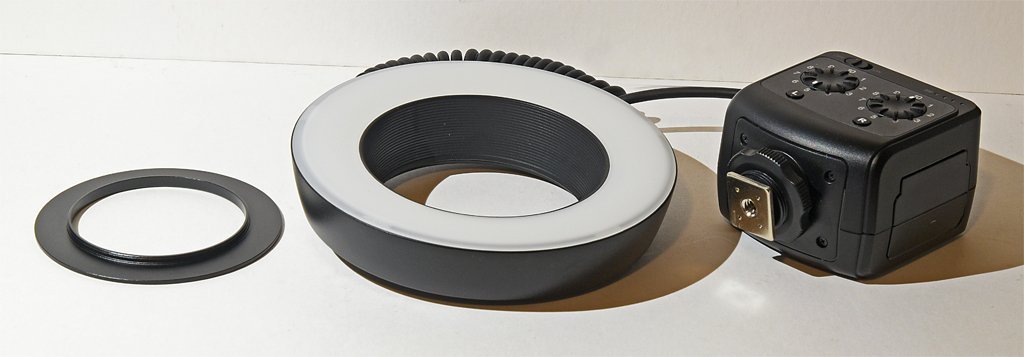
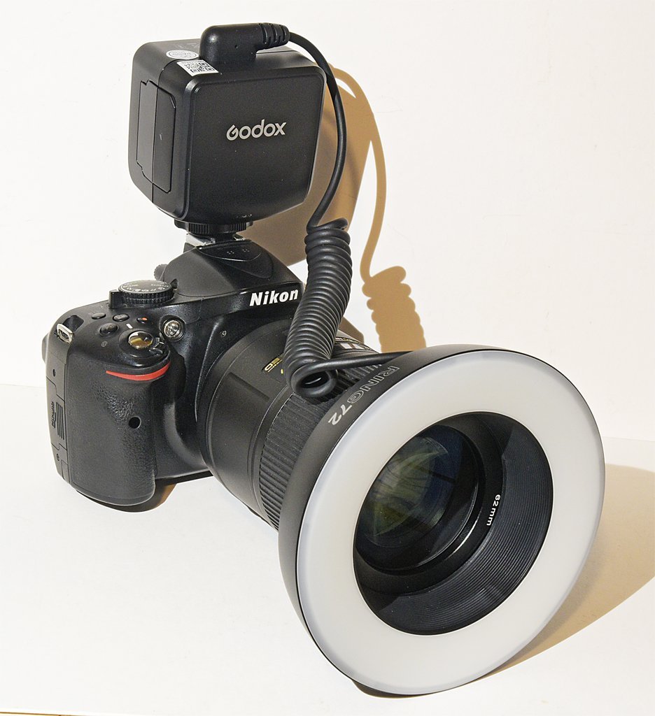
Note: This is not a product endorsement, and I have no connection to anyone selling this product. I just got one and have no idea how long it will last. I do a fair amount of macro photography and close up photography. Lighting is always a problem. I have been using everything from sunlight coming in the window to various desk lamps and such. Each required a different white balance and low light intensity and harsh shadows were always a problem. I have seen several "professional" (synonym = high price) units but never wanted to spend hundreds of dollars on one. I recently found a relatively low cost unit at a local camera store and decided to give it a try. It is a Godox Ring 72 and it cost US$75.00. The "72" refers to 72 white LEDs in the assembly. It runs on four AA cells. They also offer a rechargeable lithium battery which I do not have. There are three parts to the unit. The ring light is connected to the controller with a coiled cord. A metal adapter ring screws into the filter threads on the front of the lens. The unit comes with eight adapter rings for 49, 52, 55, 58, 62, 67, 72 and 77mm filter threads. After the adapter ring is attached to the lens the ring light just slips in place over the ring. The controller has a "cold shoe" that fits into the camera's flash unit "hot shoe" - but the ring light adapter has no electrical connection to the camera. The controller does not have to be attached to the camera, but it is very convenient to have it right in front of you. One interesting feature is that the light is divided into two banks (left and right) of 36 LEDs each. Each side can be turned on/off independently. Also, each side has a dimmer in 10 increments so you can create shadows and control light intensity. I haven't experimented with this yet, and I can see from the photos below that this may be a useful way to create shadows in closeup pictures. Here is a sample photo. This is a photo stacked image from eleven shots. The first thing I noticed is the light is very bright, so I was shooting at f/40 and 1/16 second with ISO 640! In the past I have been using something like f/8 and 1/30 second at ISO 640. I always had problems with Photoshop photo stacking when I used the wider apertures (shorter focal distances). The program had trouble determining where the edges of things like ropes were, and left a blur on either side where it chose the wrong out of focus photo. This required a LOT of editing to correct! The photo above had no editing! If you look very closely you might see a couple of places with background blur along the ropes, but if I hadn't mentioned it I'll bet you would never notice. All in all, this is a much clearer image than any I have gotten before with photo stacking. Also, you can clearly see the dust accumulation over the past few weeks when I have been working on sails and a lot of non-modelling projects! This next photo is even better! This is just three images photo stacked, with no further editing. In the past I would have used at least eight shots for this picture. It was shot at f/36 and 1 second and ISO 640. In fact, the middle photo that was focused on the bell has no noticeable blurring near or far unless you blow up the image, and then it is only slightly out of focus at the bulwark caps. With the bright light and very small apertures the depth of field in each image is about as great as the width of the model. Here is another extreme photo stacking example, using nine photos. The over all depth of the model is about 27 1/2 inches (about 700 mm). In the past I used 12 photos and there were a number of blurry places. The picture also shows that the jib boom is a bit misaligned to the starboard side (left in the photo). Shortly after rigging the bowsprit and bib boom I accidentally caught my shirtsleeve on the bowsprit and broke the freshly rigged port stay! Looks like when I re-rigged it I didn't pull it tight enough to pull the jib boom back in line. This photo does show one shortcoming of the ring light. All surfaces perpendicular to the line of sight have a lot of glare where the light is reflected back. Another problem is the lack of control of the light angle to create shadows. Maybe adjusting the relative brightness of the two banks of lights can be used to create some shadow effects - for further experimentation. This thing is new, and I have no idea how long it will last. But it was relatively inexpensive and worth trying. It is much brighter than the lights I have been using so it does allow better depth of field in the pictures. The light output is said to be 8 Watts and 5600 Kelvin (daylight color). It weighs 245 grams without batteries. Here is one more picture made from five photo stacked images shot at f/36, 1/16 second and ISO 640. Notice the very soft blurred shadows on the background. This is a lot less distracting than harsh shadows from a single distant point light.
-

Laptop recommendations?
Dr PR replied to Mike Shea's topic in CAD and 3D Modelling/Drafting Plans with Software
Here are a few more comments. 1. What CAD program do you want to use? What operating system does it run on? Get a machine that is compatible with the software. 2. Multi tasking. I have an old (2013) 3,4 GHz 6 core i7 and Windows will run 12 simultaneous tasks on these. I have seen all 6 cores running 100%, primarily for a single program, and generating a LOT of heat! So multiple cores are used. My CAD program (DesignCAD 3D Max) originated before multiple cores became common. But when it is running it does use multiple cores. Although the main CAD code may run on just one core at a time, it constantly calls other Windows library routines and they use different cores. The operating system is running on a core, and background tasks like checking for email and such run on separate cores. It is not unusual to see all six cores operating while the CAD program is running. 3. For high performance CAD rendering (even simple shading and shadows) you need a graphics card that supports OPEN GL and has as many Graphic Processor Units (GPUs) as possible. I strongly recommend nVidia graphics cards - they have been a leader in CAD graphics for decades. You must install the OPEN GL drivers in the operating system to achieve high performance. 4. Get the highest bus speed RAM that is compatible with your CPU. Even the highest speed RAM is much slower than the internal CPU data buss. With each memory access there is a relatively long (from the CPU's standpoint) wait period while the RAM access the memory location. Faster RAM means fewer wait states for the processor while the RAM reads or writes the data. Many mother boards offer two RAM configurations - straight 64 Mbyte or interleaved 32 Mbyte. With straight 64 MByte memory each read/write involves a) setting up the address, b) beginning the access, c) waiting for the RAM to access the data and d) transferring the data. Then the next RAM access (a) begins. The interleaved RAM operates faster because while data is being written/red from one bank (c, d) the other bank is starting access for the next data (a, b). CAUTION: Do not fall for the marketing hype about RAM speed! RAM modules have on-board processors that can talk to the BIOS (very lo level part of the operating system) to tell how fast the memory can operate. This allows the machine to adjust internal settings to get the high speeds. BUT Some RAM can operate at the advertised speed at the normal system operating voltages. But if you increase the voltages RAM generally runs faster. So some RAM sticks will try to jack up the voltages. This has two effects. First it increases heat in the system, and that can cause the processor to slow down - no net gain. Worse still, some RAM will try to increase bus voltages above the maximum for the processor, and that fries the processor and/or the bus controller. $$$$ up in smoke! This used to be a problem when marketing scum advertised their low performance (at normal voltages) junk as higher speed than actually rated. Read the reviews and chose the RAM and CPU carefully. -
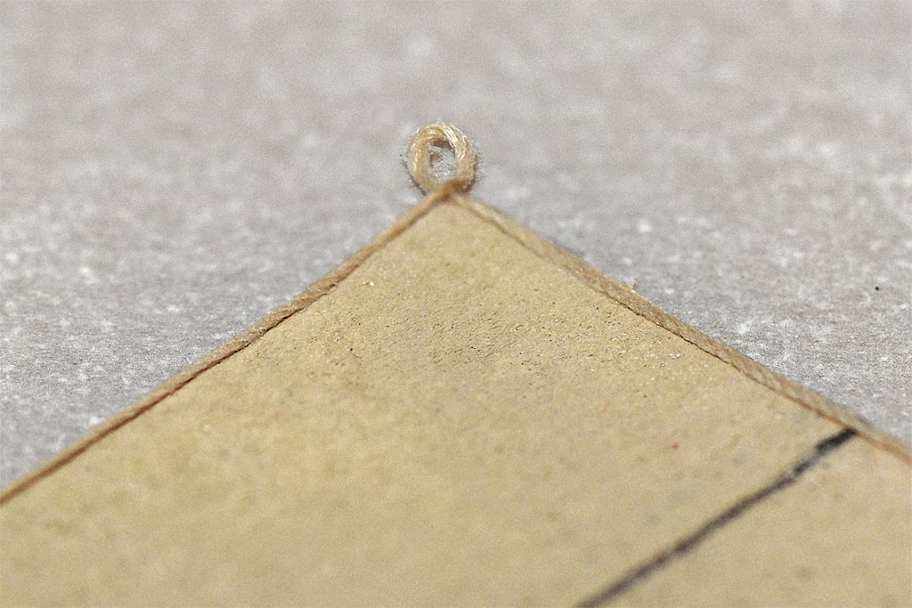
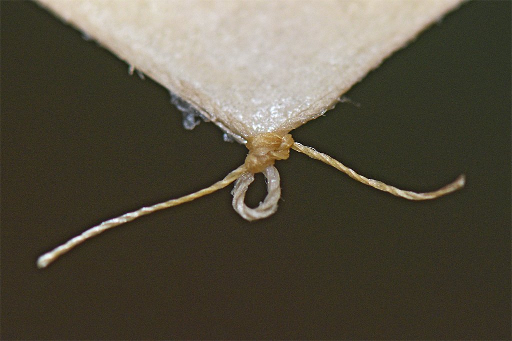
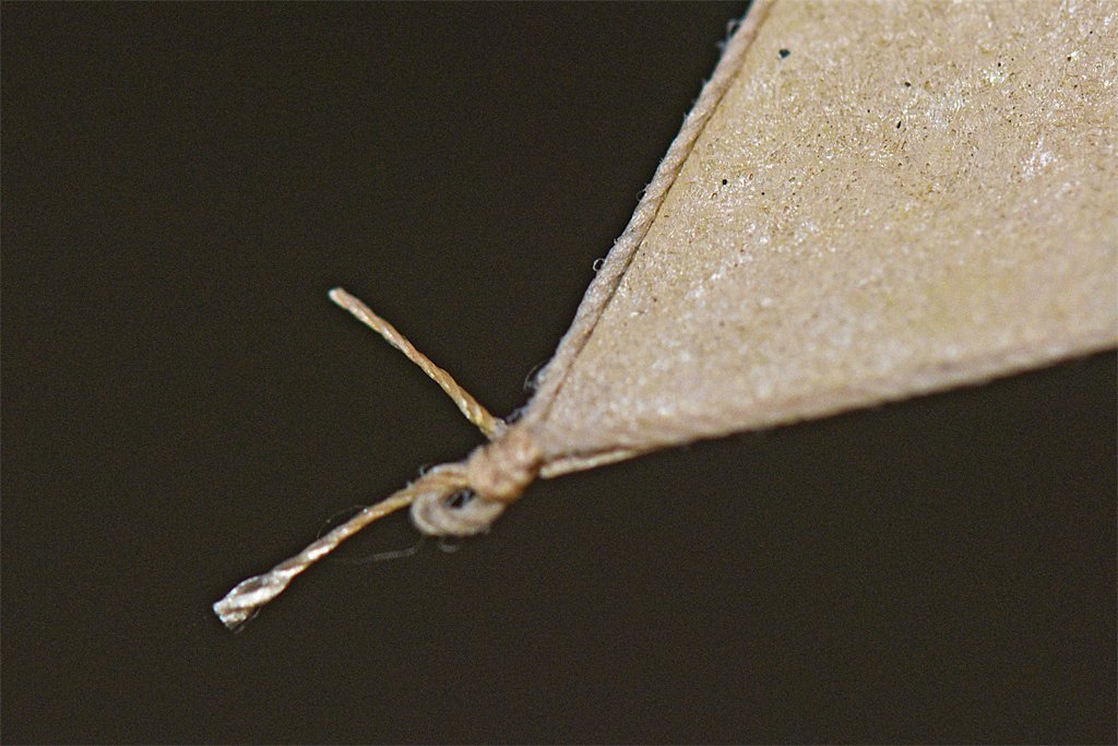
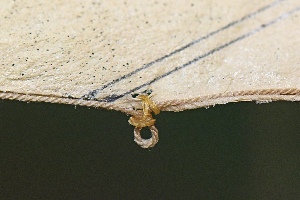
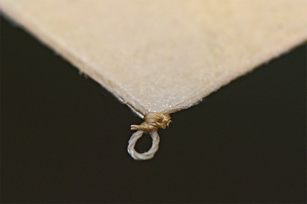
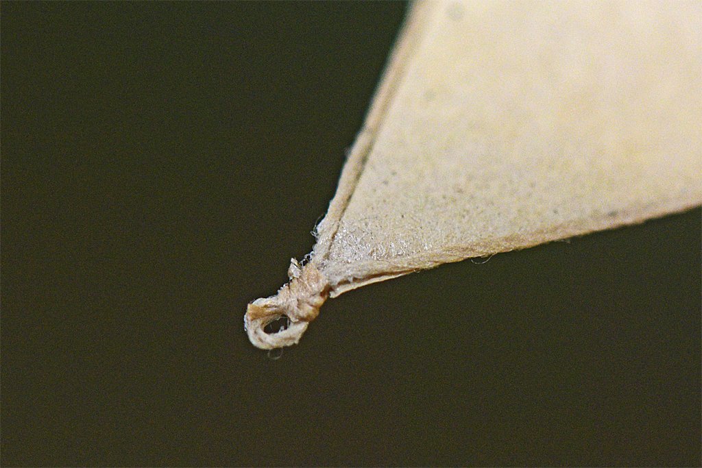
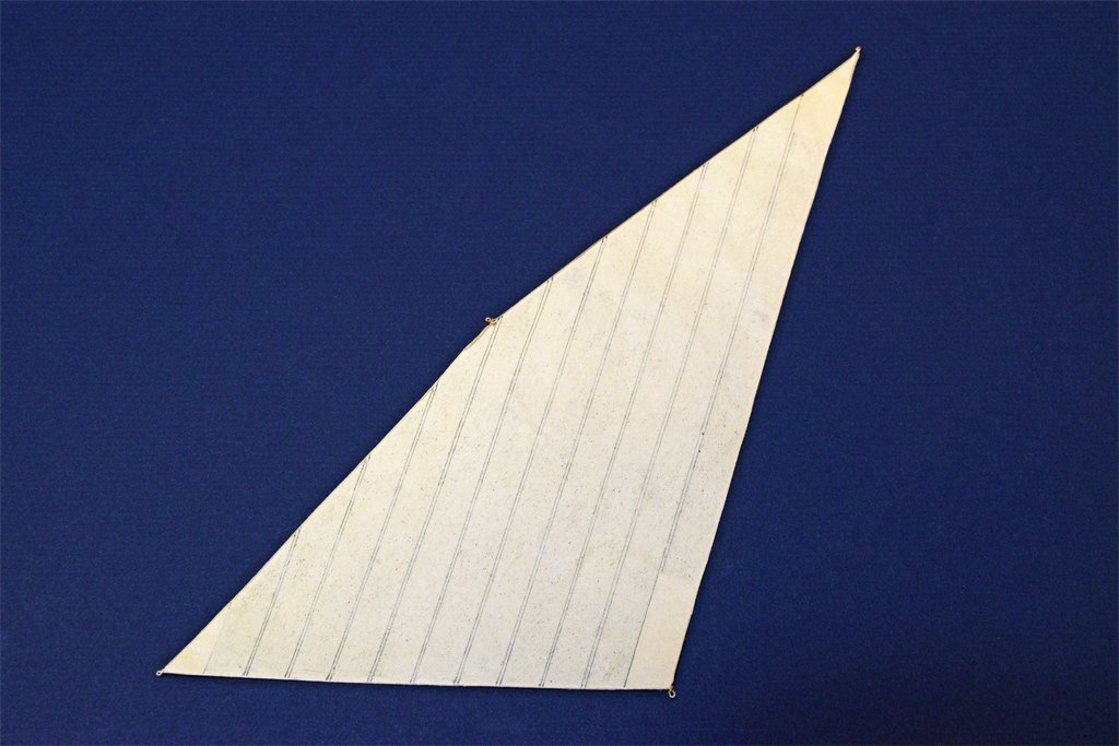
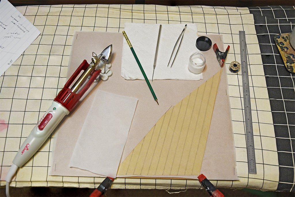
I have finally caught up on taxes, financial dealings for the nonprofit I am Treasurer for, my own savings accounts, and preparing a lecture - it has been a hectic couple of weeks - and can now get back to important things! I have a little bit of progress to report on the ship model. I left off with the preparation of a sail, the main spar gaff topsail. The next step was adding the boltropes. These are on the port side of fore-and-aft sails where the linings were placed (on square sails the bolt ropes are on the aft side of the sail). I made a few changes to my work area. I stapled a sheet of parchment paper to the cardboard work surface (the other side serves as a cutting board). I also have a piece of parchment paper to place over the glued areas for heating them with an iron. The parchment paper seems to work better than the waxed paper. The little Mini Iron II (Clover No. 9100) is a quilting iron for seams. I saw it mentioned in another post on the Forum as a plank bending tool. But it is also perfect for ironing the tablings, linings and bolt ropes after they have been glued. It is less cumbersome than a large iron and the small tip gets into tight spaces. But I also used it to iron the entire sail after everything was finished. And now I have a plank bender too! It is basically a 40 Watt/120 Volt soldering iron with specialized ironing tips. It has three heat levels, low (200F/105C), medium (390F/200C) and high(580F/295C). They recommend the low setting for silk. I also mixed up some diluted white glue 50:50 with water. I like the white glue because it dries without a trace and you can loosen it if you need to with water or the diluted glue. The small clamps are essential to prevent the sail from moving while you are attaching the ropes! This sail has a larger boltrope across the head (1/2 diameter of the main topmast stay) and smaller ropes on the leech, foot and luff (1/4 the diameter of the topmast stay). I used 0.012" (0.30 mm) rope on the head and 0.008" (0.20 mm) on the other sides. Note that the rope is glued to the port side of the sail (opposite the tablings) and not to the edge of the sail. This is the way the books say to do it and it gives a larger surface area for the glue to attach to. I do not plan to lace the bolt ropes to the sail edges as is done with real sails, because the lacing material would be microscopic. At the corners I created a small loop "cringle." This method requires a bit of patience. Of course the rope has a mind of its own and wants to be anywhere but exactly along the sail edge. So you have to do a little bit at a time and wait for the glue to dry before continuing. The little iron does speed things up a bit. There were a few places where I had to go back and reposition the rope so it was nice that the white glue can be softened after it dried. After the glue set up I seized the cringles with small stuff and white glue. This should place all the strain on the bolt ropes. As you can see in the photos there are a few small spots that can be reworked to get the rope exactly along the sail edge. After the glue dried the small stuff was trimmed. The ends of the larger rope across head of the sail were turned into a loop for a cringle and a short bit of rope was glued down along the top of the leech and luff. Small stuff was tied around the cringle for seizing. Here I did sew some small stuff through the sail material and around both ropes. The head of the sail will be laced to the spar. For this I will sew the lacing through the sail material just inside the bolt rope. Here is the finished (I hope) sail. Eight more to go (if I install the fore course).
-
Ship Ribbing with CAD?
Dr PR replied to Sanjith_D's topic in CAD and 3D Modelling/Drafting Plans with Software
I have to disagree about the accuracy of 2D drawings, and restate what Terry said. You can draw nice 2D frame/station drawings, but you have no way to tell if they will produce a smoothly faired hull surface. Even working from a Table of Offsets will not guarantee frames/stations for a smooth hull. I have done this several times, and when the 2D frame/station drawings are erected in 3D the resulting hull surface is often wavy. -
Aw, come on Valeriy! No guts, no glory!
-
Laptop recommendations?
Dr PR replied to Mike Shea's topic in CAD and 3D Modelling/Drafting Plans with Software
Mike, If all you wanted to do was use email and browse the Internet just about anything would do (even a cell phone). But if you are thinking of doing CAD work a higher clock speed (3+ GHz) and more cores (6+) is better. A video system that supports hardware acceleration (and the software drivers to work with it) is a plus. If you are going to do a lot of photo editing and storage more storage space will be needed (1 Tbyte or more). **** A fundamental problem with laptops is heat. All that electronics generates heat, and laptops have a totally inadequate cooling system. So when the processor and power supplies heat up the processor shuts down momentarily to let the cooling system catch up. So even the fastest clocked processors can end up running at a snails pace. Before buying read the reviews on line. Remember that 25% of the reviewers are morons who can't (won't) read and understand instructions and maybe 10% really know what they are talking about. But if a product has less than 70% 5 and 4 star ratings it is probably junk. -
The metal tube doesn't extend very far up into the handle. Be careful putting any strain on the handle part of the pins. My experience with 3D resin printed objects are that they are very brittle and very fragile. It should be easy to break the handle off.
-
As I understand it the term "knighthead" originated for any timber that had a fancy carved head or figure on the top. "Bitt" is a term that applies to vertical timbers that provide places to belay lines. So a bitt can be a knighthead, but not all bitts are knightheads. The rigging arrangement in the drawing in post #5 is a "whip on whip" tackle. A single block with one line fastened (the standing part) and one line running (the fall) is a whip tackle. Pulling on or letting out either fall will raise or lower the yard. Working both falls at the same time just raises or lowers the yard faster. And two lines allows twice as many people to work where deck space is limited. One of the lines from the lower block is the "standing" part that would be fastened to a cleat or eyebolt - the one on the bitt/knighthead would work. The other two lines are "running" lines that could be passed through sheaves in the bitt/knighthead and then belayed somewhere nearby. As Bob said, running the lines through the sheaves in the bitt/knightnead allows them to be pulled on horizontally to raise or lower the yard. The same redirection can be accomplished with a single "runner" block attached to a ring bolt on deck (or anywhere else) and running the fall from a tackle through the runner block.
-
It's funny how some people complain about the government as "Big Brother" when it really is companies like Apple that are the problem. They spy on you 24/7 to record everything you watch or listen to and purchase, and tax you any time they want to without any public input. Orwell was right about Big Brother, but he just picked the wrong villain.
-
Seal the wood before painting! Water based paints like acrylics raise the wood fibers and leave a "fuzzy" surface. A good sealer is shellac. You can paint over it with any paint. It dries quickly. Sand smooth with fine sand paper. Brush off sanding dust and grit and apply a second coat of sealer. Sand again and then finish with #0000 steel wool. BUT You must clean the surface after using steel wool - the tiny particles can rust and discolor the finish. I brush the hull first, and then rub down with a clean dry rag. I also have a 1 inch (25 mm) "U" magnet to pick up steel wool lint from the model surface and work bench. You can also use the fine steel wool on a coat of thoroughly dried paint to produce a "satin" finish. Some instructions say acrylic paints dry in an hour or less. They will change from "wet" as you paint to "dry" that is no longer runny, but it will still be soft and easily damaged. It may take a day or two for the acrylic material to harden, and a week or more to attain full hardness. It is OK to apply a second thin coat over an initial thin coat when the first coat is "dry," but wait a day or two before sanding.
-
I am interested in seeing how this works. I have an old compressor that makes only about 18 psi and that doesn't work with some paints and tips.
-
For me Marquardt's The global Schooner is a must have book for working on schooners. It is a "Lees" for fore and aft rigged vessels.It has some history, but much of the book is about howfore and aft craft were built and rigged, and the appendices have a lot of tables of historical data.
-
Steve, 1. More belaying points is better than not enough! 2. I think you are correct that the spaces between pins should be over the gun ports. When the cannons recoil you don't want them hitting belaying pins. 3. Take what I have said in my build with a grain (or spoonful) of salt. It is a hypothetical build, so I can do whatever I can imagine. I am building that schooner to learn about schooners, and not to build a correct replica of any particular vessel. 4. With very few exceptions, we are never going to know exactly how any particular historical vessel was rigged, especially from times before photography and modern engineering practices. My philosophy is to put myself in the bosun's shoes - how do I make this work so the Captain doesn't chew my posterior? **** I wasn't around centuries ago, but I did my time on ships in the mid 20th century. Whenever the ship's bosun decided he needed a new belaying point - a cleat or bollard - he talked to the chiefs in engineering and soon a new fixture appeared. Sometimes he took a five pound can of coffee from ship's stores over to a friend in the shipyard and came back with what he wanted. And for something really big a canned ham would usually do the trick. Official blueprints weren't needed. Where there was a will there was a way!
-
Karl Heintz Marquardt's The Global Schooner (Chapter 1, Origin of Schooners) shows numerous examples of this "bermuda rig" dating from a 1526 Spanish account of a Peruvian raft, and a Dutch sketch of one of these rafts from 1615. The Dutch were building similar two mast triangular sail torentuig rigged vessels in the early 1600s, and possibly introduced it into the Bermudas in the 1620s. By the late 1620s the Dutch had developed a refined version called the speljacht. It is suggested that these vessels might be the origin of all schooners in Europe and then the Americas.
-
Steve, You are making good progress. I have been working on the rigging and belaying plan of my topsail schooner model for some time, and routing the lines without any fouling is tricky! Chapelle's The Search for Speed Under Sail (W. W. Norton & Company, New York & London, 1967) has a two page drawing of the Prince de Neufchatel sail plan, including a belaying plan, between pages 229-230. It is pretty small print but I can read it clearly with a magnifier. This is very rare! Most sail plans just show lines going down to deck somewhere. Few plans actually show where the lines belay. He shows nine pins forward and five aft (9-5) of the gun on the aft pin rail, and 4-8-3 (fore to aft) on the forward pin rail.
-
Jsk, I have heard of using coffee filters (and tea bags) for parts of models (like tarpaulins over hatches). I just measured the thickness of an ordinary coffee filter paper, and it is 0.0005 inch (0.0127 mm)! That is thinner than the silk span, and would be closer to scale for sails on 1:64, 1:75 and 1:96 or 1:100 scale models. The only problem I see is that the filters I have are too small for any of the sails on my 1:48 model. But if you can find sheets of coffee filter paper (I'll bet artists use it for something) I can see no reason not to use it. Come to think of it, we did have large sheets of filter paper of several different grades (thicknesses) in our chemistry labs in college, so it is probably available through chemistry supply companies. Paper chromatography paper is similar to filter paper.
-
Gregory, I glued two pieces of parchment paper together with white glue and then clamped them together. After about eight hours I removed the clamp and the two pieces pulled apart with almost no force needed. I think parchment paper has another advantage. The wax on waxed paper melts when heated and sticks to the sail material (and probably the iron). I suspect this is part of the problem with the tabling material lifting off the sail with the waxed paper that Lauria mentions. Also, when I used waxed paper under the sail to prevent the glue from binding to the cardboard work top the sail stuck to the waxed paper sheet (but not very tightly). I will use parchment paper instead of waxed paper for making the next sails. Note: I did use parchment paper and it worked as well as or better than waxed paper.
-
Roger, Where did you get the square brass wire? Is it available commercially or did you use a draw plate? It may be a "fussy detail" but this is what sets an excellent model apart from an ordinary one.
-
Gregory, I was wondering that myself. I have a roll of parchment paper in the drawer with the waxed paper. The virtue of waxed paper is that the glue isn't supposed to stick to it. The white glue doesn't actually glue to the waxed paper because it can't soak in, but it does adhere loosely. I'll have to experiment with the parchment paper.
-
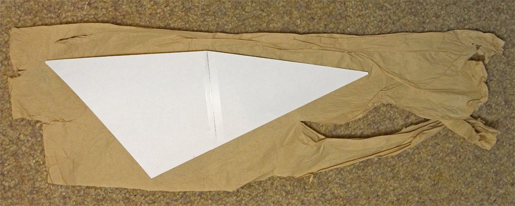
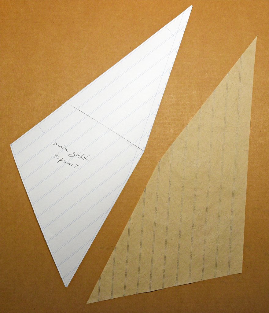
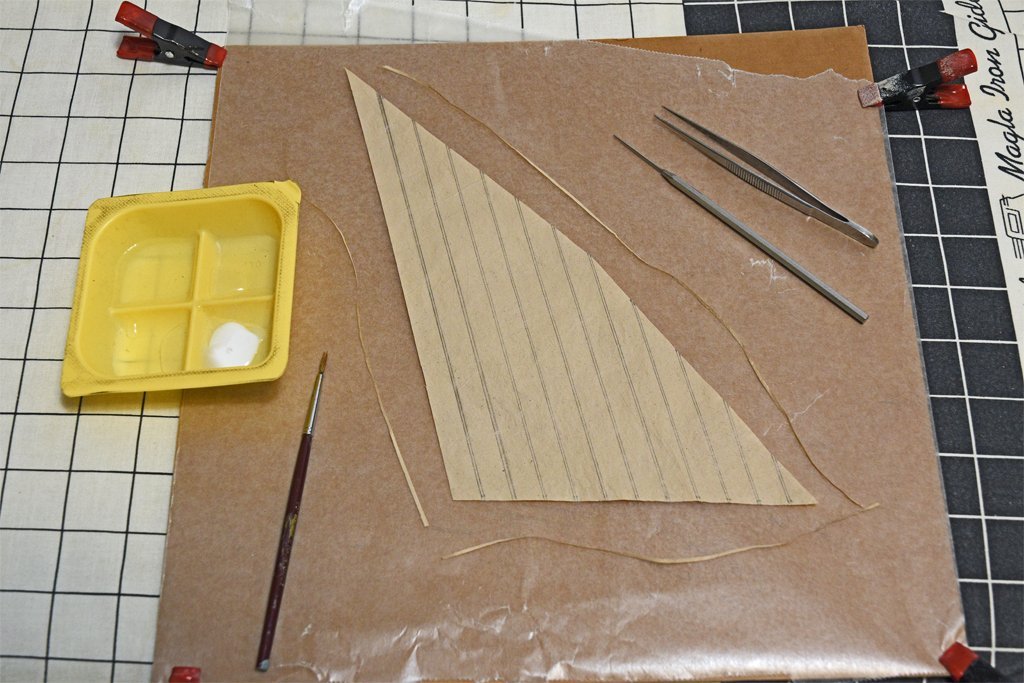
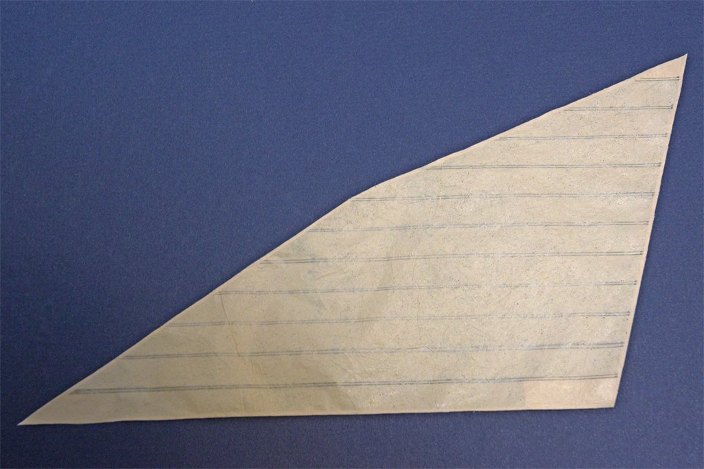
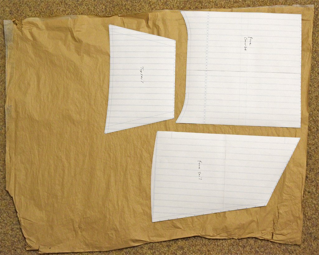
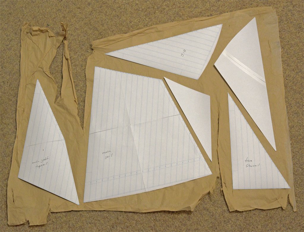
Here is my first attempt to make a sail. First I arranged the sail templates on the two usable sheets of sail material. Then I cut off one of the ragged sides of the second sheet where the template for the main gaff topsail fit. Here is the sail piece and template after trimming the sail from the sheet. My first mistake was failing to draw on the cloth lines before cutting the material from the sheet. It probably would have been easier to draw the sail outline and cloth lines on the sail material sheet before cutting the sail from the sheet. This is what Tom Lauria suggests. I just aligned the template edges with the sail edges and drew tic marks where the lines should terminate. Then I penciled in the lines with a mechanical drawing pencil, using #2 lead. A drawback to this method is that the tic marks are visible on the sail after the lines were drawn. I also discovered that even though the sail material is very thin and easy to wrinkle I could erase the lines I screwed up and draw them again. There were a couple of opportunities for that experiment! The dry sail material is pretty tough and I have seen no tendency to tear. One slight variation from Laura's procedure was cutting the tabling strips from along the edge of the hole where the sail piece had been cut out. He just cut a bunch of narrow strips from an unused part of the sail material sheet. Here is the work area for gluing the tablings and linings to the sail. The plastic tray held white glue (school glue, Elmer's glue, etc.) and water. I used a fairly narrow paint brush. Tweezers were necessary for handling the thin tabling strips and the lining pieces. I also had a thin probe to help lift stray ends and realign them. One thing I did different from Lauria's tutorial was to cover the work area (a sheet of cardboard) with waxed paper that was clipped to the corners of the cardboard. I was worried that the glue would stick the sail to the cardboard. The waxed paper worked well to prevent this. Here is the "finished" sail ready to add the bolt ropes. The material is slightly translucent, and against the dark background you can see the linings at the corners (on the back or port side of the sail). The thin tabling strips are visible along the sail edges on the starboard side of the sail. After it has dried overnight I will iron the sail again to take out wrinkles. (It ironed out perfectly smooth the next morning!) One thing about this process that isn't clear from Lauria's video is whether the white glue was diluted before using. He used a wet brush dipped into the glue, so in that respect the glue was diluted. This was a good thing because it delayed the drying of the glue to allow things to be moved into position. But the strength of the glue was unpredictable, depending upon how wet the brush was and whether the glue was becoming diluted from the water on the brush as it was dipped into the glue. Sometimes the glue was thicker than at other times. I am concerned that in some places the glue was too watery and the pieces may not remain glued together. I may try just using diluted glue (1:1 with water). I did have a few problems. First off I got glue on my finger tips and then they stuck to things I didn't want to pull on. I kept a paper towel close by to wipe my fingers on. The long tabling strips were a bit unwieldy and tended to go out of line or settle with raised sections. It was easy to correct this using the metal point or just the tweezers to fit in under the wayward portions and pull them straight. I did use a piece of waxed paper on top of the glued sections as I heated them with the iron. I guess I was using too much glue because I had the same problem Lauria demonstrated in his video. The tabling strips often stuck to the piece of waxed paper as I lifted it. With practice I learned how to lift the paper from the appropriate direction to avoid this problem. But another problem I saw arose from the extra glue on the lower sheet of waxed paper after I painted a line of glue along the edges of the sail. This glue tended to glue the sail to the waxed paper after I had heated the area with the iron. So after each tabling I wiped the waxed paper sheet with the paper towel to remove glue. All part of the learning curve!
-
Do you ever buy from McMaster-Carr? It is an industrial supplier but they sell small quantities to hobbyists too. I have been purchasing from them for decades. Top quality items at prices better than you find in hobby shops (if you can still find a hobby shop). They have quite a selection of plastic and metal stock for machining. The only shortcoming is that much of their stock is larger sizes and not the very small things for modelling. https://www.mcmaster.com/products/rods/?s=plastic+rods Look around their site and you will find all sorts of useful things!


