HOLIDAY DONATION DRIVE - SUPPORT MSW - DO YOUR PART TO KEEP THIS GREAT FORUM GOING! (Only 13 donations so far - C'mon guys!)
×


Dr PR
-
Posts
2,406 -
Joined
-
Last visited
Content Type
Profiles
Forums
Gallery
Events
Everything posted by Dr PR
-
 I tried one more stain, a Minwax oil based "gunstock" color. The color closely matches the color of the wood I used for the bowsprit after it is coated with shellac. I applied it to the four sides (left) of the test dowel that the masts were cut from, and let it stay on for 3, 5 10 and 15 minutes on different sides before wiping it off. I also did this with the red mahogany stain (right). The cherry stain (middle) was applied for 3 and 6 minutes, overlapping. Allowing the stain to remain on the wood longer produced little or no visible differences. The results were horrible in all cases. Punt! The reason I wanted to stain the basswood masts was to try to match the color of the bowsprit wood. I have decided to just paint the bowsprit, masts and spars. Then there will be no problem getting matching colors. Besides, at 1:48 scale the wood grain wouldn't be visible anyway.
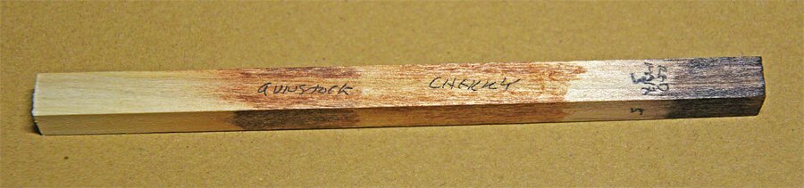
-
Many excellent examples have been shown, illustrating the many ways sails may be handled and operational states ships may be in. There is one other consideration - much of the running rigging is not aloft if the sail is not aloft (flying or furled). But the running rigging makes up a majority of the lines in the rigging. So if you don't put sails on the model the rigging can look pretty sparse. An option is to place the running rigging aloft, but bring together the ends of the lines that normally attach to the sails. For example, the jib halliard (hoists the sail) can be brought down and hooked to the jib downhaul (pulls the sail down) so the lines are rigged and waiting for the sail to be brought up and attached. So the sail is not in the way of viewing your handiwork but most of the rigging is in place. A lot of the running rigging can be modeled this way. It just depends on what you want to see. If sails and rigging are not your cup of tea you may want to just model the hull with minimal or no masts and rigging.
-
Please excuse my ignorance, but I have seen several discussions of "round tuck" and "square tuck" and they are all as clear as mud. What is the part that is curved in a round tuck? There are "stern pieces" and "transoms" and these terms seem to be used interchangeably. There is the aft most, more or less vertical planking below the rail that is sometimes decorated and carries the vessel's name. It is usually called the transom in modern vessels. It can be flat or curved from side to side. Then there is the transverse (side to side) planking below the stern piece/transom that extends down and forward to the stern post that the rudder post usually passes through. The planking below the stern is sometimes shown flat or curved (along the centerline). I initially interpreted this to be the "flat or "round" tuck. But it can also be flat or curved transversely, with the part at the centerline more aft than at the sides. So is this the curve of the round tuck? But then I learned that some people say the "round" or "square" tuck had nothing to do with the curvature of the transom or stern piece but was the way the fore and aft planking terminated at the bottom of the planking below the stern (whether curved or flat either vertically and/or transversely). So there are four possible curvatures that could be interpreted by a novice as "round," and very few (if any) writers seem to understand the potential for confusion and just assume everyone knows what they are thinking. Some might call this "functional illiteracy" or the inability to communicate effectively. So can someone tell me what is the common or "official" names for: 1. The more or less vertical piece that extends up to the top rail? It is typically made of horizontal planking that may be flat or curved transversely (side to side). 2. The angled planking below this piece (that the rudder post usually passes through) that can be flat or curved vertically along the centerline, and flat or curved horizontally transversely? 3. An accurate description of round tuck and square tuck and how it relates to 1 and 2?
-
Topsail schooner sail plans and rigging
Dr PR replied to Dr PR's topic in Masting, rigging and sails
Bob, I am glad it has been helpful. After wading through all this information I hoped that putting it here would be useful to someone else.- 104 replies
-
- 7
-

-

-
- schooner rigging
- Topsail schooner
- (and 1 more)
-
The upper drawing in post #41 is a "jackyard topsail." Leather's "Gaff Rig Handbook" says it was invented to get around rules for class racing where the gaff was limited in length. The gaff yard increased the sail area over what the other gaff topsails provided. Without the spar attached to the gaff and just the spar hoisted to the mast top it would be a "spar gaff topsail." This was also a way to increase the sail area and raise it higher to catch winds above the surface. Without either of the spars it is a gaff topsail - but I have found at least eight different gaff topsail configurations. I have posted quite a bit of information about schooner sails and rigging in the following link. Some of it may be of use in your build. https://modelshipworld.com/topic/25679-topsail-schooner-sail-plans-and-rigging/?do=findComment&comment=750865
-
I have seen one reference where Douglas fir (Pseudotsuga menziesii) was used for decking on a fairly recent build. It still grows in the Pacific Northwest, although almost all of the original native forests have been clearcut. I don't think it would be a good material for decking. Even here in Oregon where it is harvested we don't use it for decks or fencing that is exposed to the (wet) weather. It is a fairly soft wood and rots quickly. The blueprints for the Cleveland class cruisers of the late 1930s and 1940s say they had two inch laminated planking for the decks. The upper one inch was teak and the lower one inch was Douglas fir. I suspect this was common on all US Navy ships of the period. Douglas fir was cheaper and more readily available than teak. So the more durable teak was exposed to the elements and the Douglas fir was a filler. I have a piece of the teak deck from the USS Oklahoma City CLG-5 that was removed before the ship was used as a target and sunk in 1999. So teak was still being used as late as 1979 when the ship was decommissioned. We replaced the decking in Japan in the early 1970s but I didn't pay any attention to the materials so I don't know if it was laminated.
-
I have read that sheer poles were introduced in the mid 1800s, so if your vessel dates back before about 1830 it wouldn't have had sheer poles. I seem to recall that I was able to adjust the individual strands of the lanyards that tie the deadeyes together to create a counter twist. Pulling one side (inboard or outboard) tighter creates a torque to twist the upper deadeye and shroud. This takes a lot of fiddling but I have two models where the deadeyes have remained aligned correctly for decades. After you get the deadeyes aligned and they have stayed that was for a few days you can paint the deadeyes and lanyards with varnish or clear paint (flat or satin) to hold things in place.
-
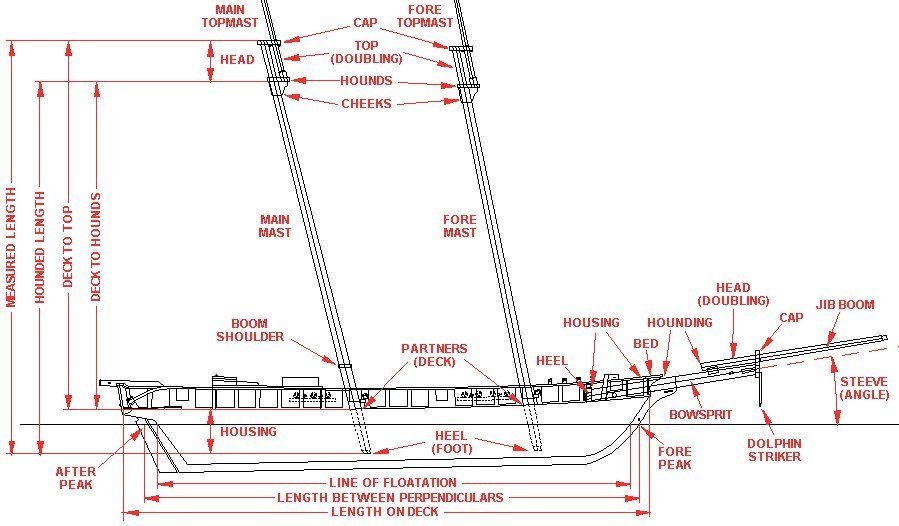
Gregg, I have had the same problem trying to decipher what different authors and plans mean by "mast length." Most authors just assume you can read their minds! I have encountered four different "mast lengths" in references on mast construction. This drawing shows what the terms "measured length," "hounded length," "deck to top" and "deck to hounds" mean. Measured length and hounded length are the two most commonly used terms for "mast length," although most authors just say "mast length" without actually saying which actual meaning they are using. The same ambiguity often applies to the "length" of the ship, with the three measurements shown in the drawing being used for the length of the ship. I can't see the tops of the masts in the image you posted, but I suspect the "measured length" is what they are talking about. It is the dowel length, and that has to include the measured length from the heel to the cap.
- 65 replies
-
- 3
-
-
- Ballahoo
- Caldercraft
- (and 1 more)
-
One way to hide the jaggies would be to cut one edge straight and put all the steps on the other edge. Then make the edge with the steps the inside edge that will be hidden by the overlapping plank. I need to make a small boat for my current build so I am watching with interest.
-
George, I have been experimenting with Minwax wood stains. I have been testing on a scrap of basswood that the masts were cut from. Since I was trying to match what I think is mahogany on the bowsprit - after it is sealed with clear shellac - I tried their red mahogany. After applying and waiting three minutes (according to instructions on the can) I wiped it off. It came out dark brown with no reddish tint, nothing like the color on the can! Then I tried Minwax cherry stain. Again the color on the can was close to what I wanted, and the instructions said I could apply multiple coats to get a darker color. However, I was careless and bought a can of their "gel stain." It is like brown jello. After applying it I had a very close match to what I wanted, but after wiping it off almost no color remained. Maybe a very, very pale hint of brown. I have applied three coats and always got exactly the same result - almost no color. So much for Minwax stains! As you night expect I am a bit frustrated. I'll look up the stains you mentioned and maybe give them a try. But right now I am just thinking of getting some acrylic paints and mixing up a suitable color.
-
Even in the modern US Navy some color schemes were the prerogative of the Captain, or even the bosun's mates. For example, on some ships the capstans, catheads or chain pipes were painted red on the port side and green on the starboard. On other ships they might be deck grey. Awnings might be grey or white, etc. On the OK City Captain Howell ran a no nonsense warship grey ship. We got a new Executive Officer who wanted to replace the grey canvas with white, with lots of frills and McNanara's lace, and paint all the plumbing a rainbow of colors. "Rodney," Captain Howell replied, "you want to turn my ship into a circus boat!" White awnings in particular were a bad idea on an oil or coal burning ship, especially if it spends time in harbor with other ships. They "blow stacks" during the mid watches to clear soot out of the smoke pipes, and the soot settles on everything. White canvas has to be scrubbed every morning by the deck crews.
-
Jim. I have been thinking about that. The bulwark brown is more of a milk chocolate color - not quite as red as the mahogany. But I guess it would make sense to use that brown for the masts and bowsprit since it was already used on the vessel. Thinking in terms of the early 1800s and what was available (cheap) at the time, if they had the brown they could use it to seal the masts and bowsprits. I have some Minwax cherrywood gel stain that I will try on a scrap of the basswood dowel to see if it comes close to the bowsprit wood with clear shellac on it. It seems to be a bit lighter than the mahogany, but the can says I can apply multiple coats to get a darker stain. I'll see how that works out. If not, I can always paint the bowsprit black.
-
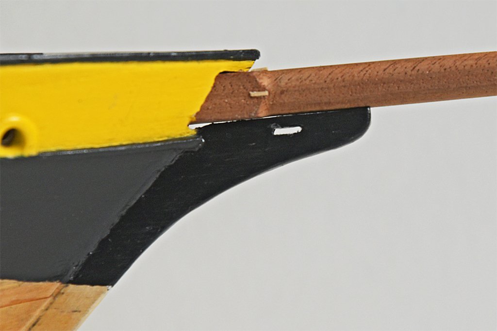
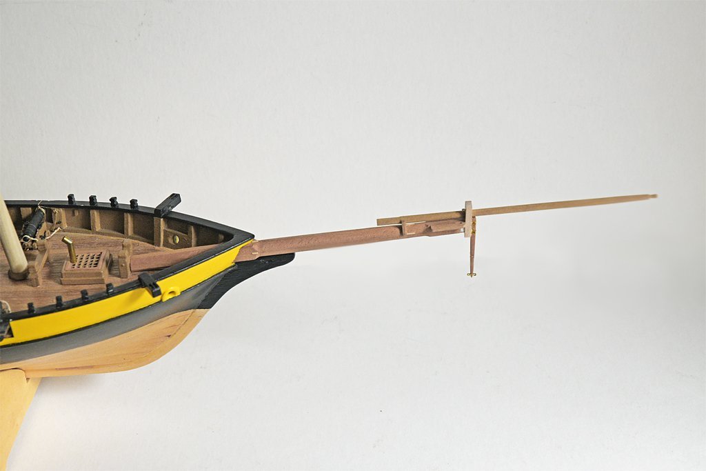
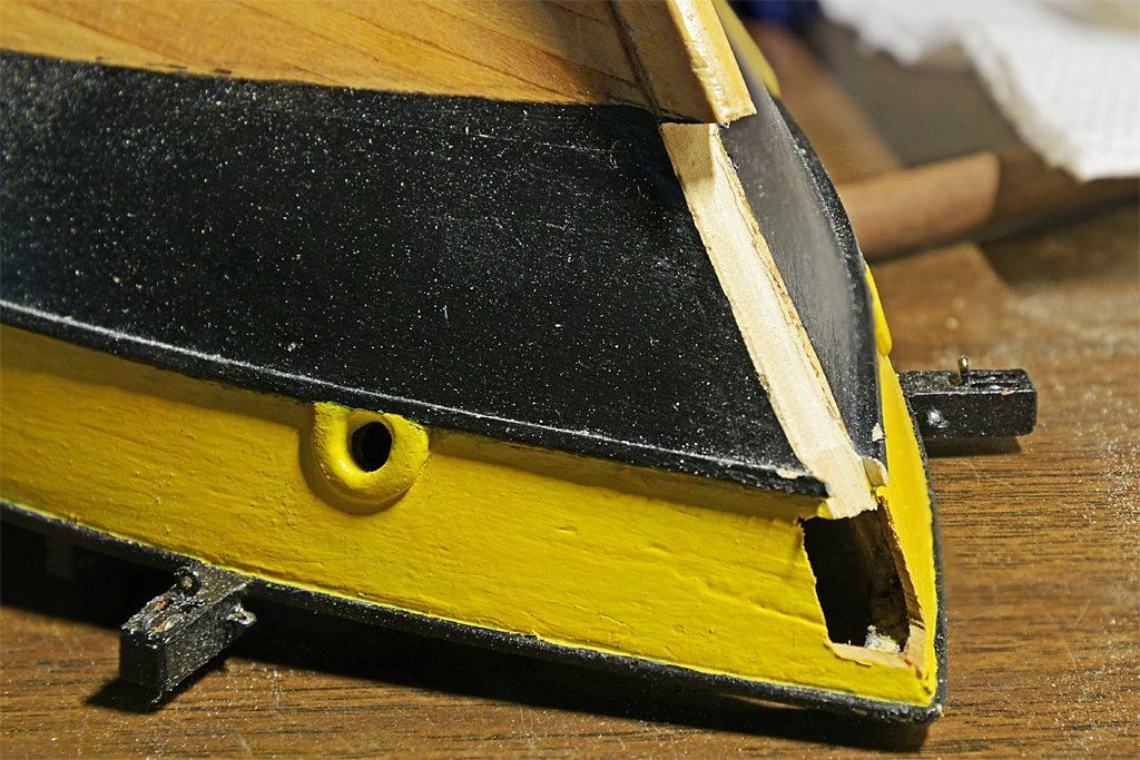
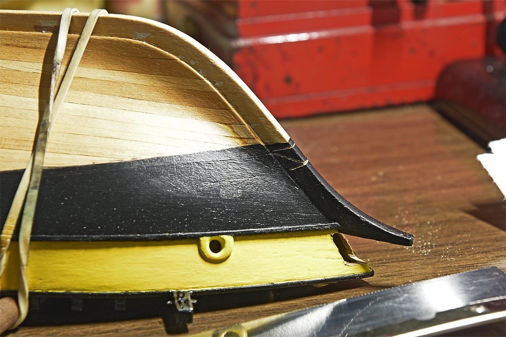
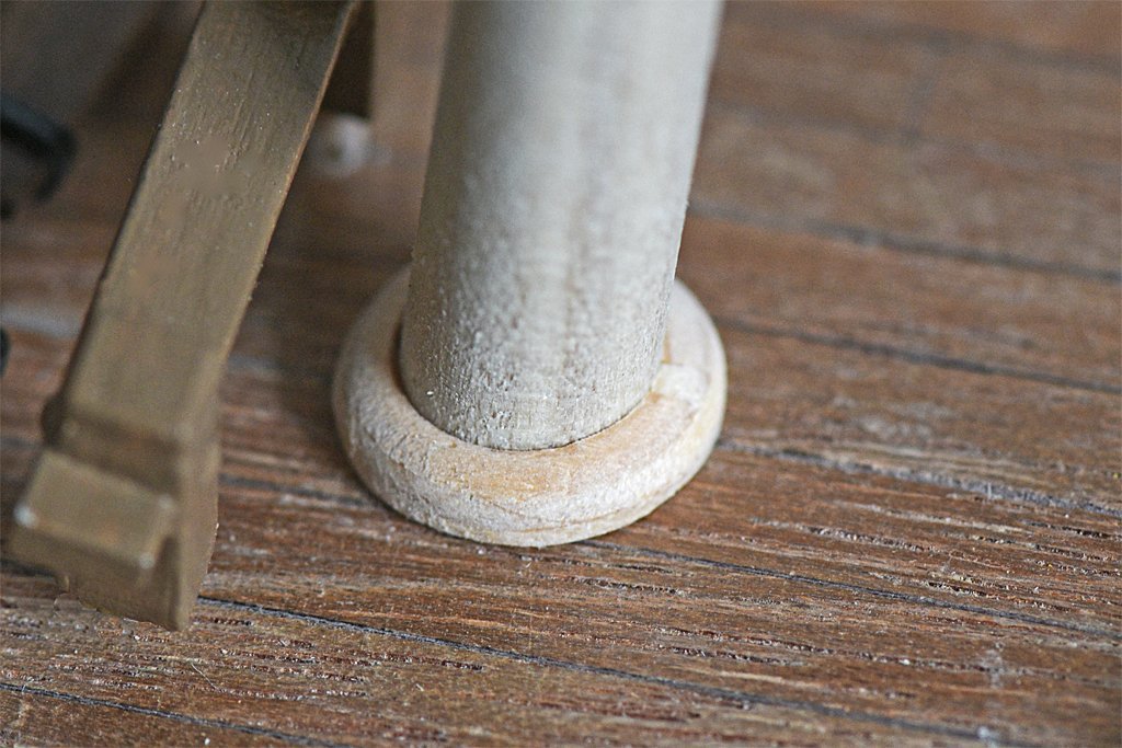
Thanks George and OldSalt 1950. The repair came out OK. Now there is a place for the gammoning ropes. On some ships there was a wide gap between the knee and the bowsprit, and the gammoning was tied across horizontally in that gap. But on many schooners the bowsprit seemed to rest on the knee as shown here, so the cross tie wasn't used. For a while I considered a bit fancier knee with a bit of scrolling at the forward end. But I decided that wasn't necessary. These little revenue cutters were pretty basic, with few frills. There are many small details I have to add to the hull and deck before it is ready for rigging. But my biggest problem now is deciding how to paint the masts and bowsprit. I have created a problem for myself. I used a piece of square dowel I had on hand for the bowsprit. I think it is mahogany that I bought at our local hobby shop decades ago. It has a nice medium brown color. When I started looking for matching wood for the masts I learned you can't import mahogany into the US any more - it has almost been exterminated from the Brazilian forests. I had to settle for square basswood dowels for the masts, and you can see in the picture how much lighter they are than the bowsprit. That's poor planning! I wanted to just finish the bowsprit and masts in a natural wood color, but so far I haven't found a stain that will darken the basswood masts to match the bowsprit. The Minwax red mahogany stain is way too dark, even if it is wiped off immediately after applying. I am considering the color scheme on the modern La Recouvrance and Pride of Baltimore II schooners. The bowsprit is painted black from heel to the cap, and the jib boom is a natural wood color. The lower masts are natural wood color from the deck up to the hounds. The cheeks, trestletrees and crosstrees, mast head and cap are black. The topmast is natural wood color, with the heel black on the La Recouvrance. The spars are natural wood color, with the yardarms (tips of the spars) black. So I would lose that nice natural mahogany color on the bowsprit but I will be able to stain the masts a darker wood color than the bare basswood without trying to match the bowsprit color. And I have lots of black paint!
-
Valeriy is obviously a very experienced model maker. In addition to the clean crisp lines I am impressed that he really understands the order that the assembly needs to go together. And he doesn't forget to clean off the dust before he takes his photos!
-
I have searched through the forum for information about the color or finish on masts, mast tops and bowsprits and there are only a few posts. I thought I would create a separate topic. I am building a model of an early 1800s American Revenue Service schooner, but I am interested in painting practices on other ship types, eras and nationalities as well. I have found no historical records of the colors or finishes on revenue cutter masts. Rather, in early American vessels, including the early US Navy, there seems to be no standard color scheme. Many ship owners and captains followed British practice, but others didn't. Sometime after about 1830 it seems the US Navy did adopt a standard color scheme. Were masts and bowsprits painted or just left the natural wood color? I have seen both on modern models. I have read that some vessels had "natural wood color" masts, but the masts were greased where the mast hoops moved, and were darker as a result in these parts. If painted, what colors were common? Was the entire mast painted or only parts of it? How did this vary over time? What color was common for the tops (doubling and crosstrees)? I have seen black on some models and white on others. What periods were these colors common? Another interesting discussion was about the color of mast hoops. I read that the hoops were a different color from the masts in the British (and other) navy up to Trafalgar. Then Nelson ordered that the mast hoops be repainted to the same color as the masts so the British ships could be distinguished easily from the opposing ships. Unfortunately, the posts discussion this didn't say what the colors were for the masts and hoops before Trafalgar! All comments and discussion are welcome!
-
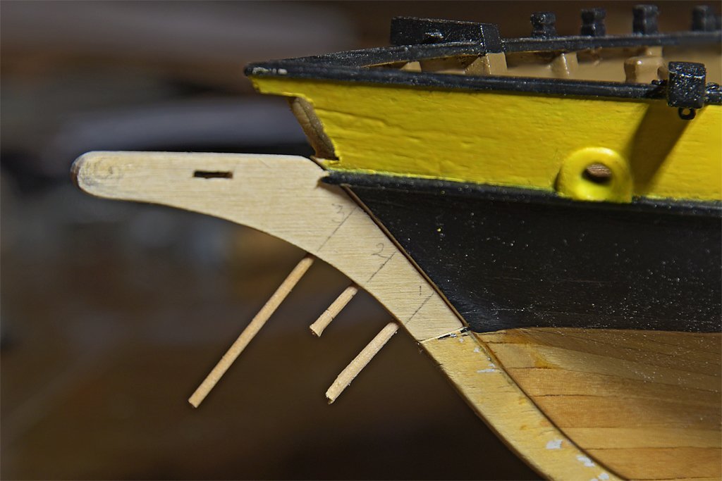
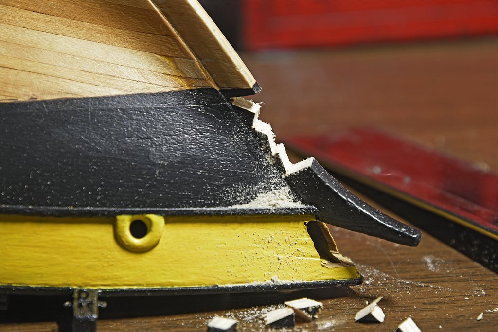
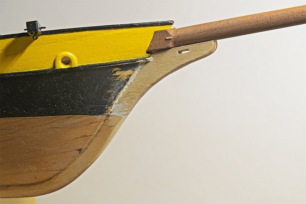
I performed surgery on the bow of the ship. The "knee" that projected under the bowsprit wasn't long enough or thick enough for the gammoning that was needed. Between the 1980s when this project was started and through several moves about 1/2 inch (12.5 mm) was broken off the tip. I decided it was about time to replace the knee. The amputation began with a series of saw cuts to remove material. I was a bit anxious about working on this because the plywood the stem was made of was quite old and the layers might separate. However the wood was soft and cut easily. The operation was successful and the cut area cleaned up nicely. The next step was to fashion the prosthesis out of a (relatively) new piece of plywood. I selected a piece from my scrap box and shaped one edge to fit the place on the hull. After that I used a coping saw to rough out the part. Then I used files to refine the edges to fit the hull and the bowsprit. Finally I finished shaping the part so the curves matched the curves of the hull. After cutting the hole for the gammoning rope I drilled three 1/16 inch (1.5 mm) holes through the part for wooden pegs to give strength to the joint when it was glued to the hull. I made the pegs from bamboo cooking skewers. The new knee served as the template for drilling holes in the hull for the pegs. The photo on the left shows the part temporarily pegged in place. On the right is the finished part glued in place, with some putty to fill in a few chips and create a filet where the planking met the stem. The repair is very sturdy. It looked as if the knee might be a bit too long so I took measurements from a dozen drawings in Marquardt's "The Global Schooner" and averaged the results. The length of the knee was compared with the bowsprit length from the hull planking to the bowsprit cap. The length of the knee varied from 0.17 to 0.39 times the length of the bowsprit outside the hull, with an average of 0.25. The new piece was a bit longer than average but I trimmed it back to 1/4 the length of the bowsprit outside the hull. Now I just need to seal the wood and paint the bow.
- 421 replies
-
- 10
-
-
Off and running with the schooner rigged pond yacht
Dr PR replied to Elmina's topic in Masting, rigging and sails
Fore-and-aft rigged schooners often did not have rat lines, and the spacing between your shrouds makes it unlikely that the boat had them. Access to the upper mast was either by bosun's chair as Kieth said, or just by climbing the mast rings when the sails were set. And "bosun's chair" is a rather loosely defined term. Often it is just a rope sling that you sit on while someone hoists you up the mast. -
I have been using the free Chitubox and I am satisfied within how it works. Their tech support is pretty amazing, often responding within a few minutes to my email questions! 1. You can create custom settings for different resins and save them for future reference. 2. You can add settings for any printer - if you know them. For my Anycubic Mono I just started their Photon Workshop slicer program (not nearly as good as Chitubox) and copied the settings from it. 3. Chitubox sometimes doesn't add enough default supports and the print fails, leaving the part stuck to the FEP film. I have been manually placing supports with mostly good results. Most of the failures I am seeing are always due to not enough supports near edges and corners. If it isn't supported a surface will flex during printing and come out warped. Another related problem is supports that are too narrow at the contact point with the print part - the support doesn't connect to the printed part and is worthless. 4. Chitubox offers many options for designing individual supports, including the base shape and size, support shape and width, support end diameter, shape and depth of penetration into the surface. The only thing that doesn't seem to work correctly is cross links between supports. For me these are a nuisance, but turning them off in the settings doesn't prevent the program from adding them anyway. These can make it very difficult to remove supports from fine details. **** On another topic, I have using denatured alcohol (95% ethanol and 5% methanol). This was recommended by Anycubic for cleaning their Basic Grey resin. It is sold in gallon cans for about $18 the last time I looked - look for it in the paint stripper and wood finish products. It has always been cheaper that 95% isopropanol (isopropyl alcohol), primarily because it is available in gallon quantities. **** And now a question: I read in someone's post that they used hot water or a heat gun to soften warped pieces and then bend them back into shape. Has anyone tried this? Do you heat the part before curing or after? The single greatest frustration I have found with 3D printing is that thin details like hand rails are often distorted by the forces of separating the print from the FEP and then pressures from resin flow as the part returns to print the next layer. These parts are always bent between the supports, and often come out "fat" in between supports. So far this problem has made 3D printing useless for many of the things I have tried to make. If I can reshape the warped railings and pipes after printing there are a lot more things I could use 3D printing for.
-
Off and running with the schooner rigged pond yacht
Dr PR replied to Elmina's topic in Masting, rigging and sails
Belaying plans (where the rigging tied off on deck) are rarely found for ships because everyone knew how to do it and didn't need a plan. The fore-and-aft schooner rig was pretty simple (compared to a square rigged ship). Normally there would be pin rails along the bulwarks along the sides of the hull (but your model doesn't have bulwarks) and the fife rails at the base of the masts. Lines could also belay to ring bolts in the deck at the base of the masts and along bulwarks and cleats near the bottom of the masts and on the bulwarks. The general rules for belaying the running rigging were: 1. Lines from lower on the mast would go to the more forward belaying points and lines from higher on the mast would go to belaying points more aft on the rails. This makes sense because masts often had rakes leaning aft so the origins for lines higher on the mast would be more aft than those lower down. A few vessels had forward raking fore masts so the rule would be reversed in this case. 2. Lines originating on or close to the masts led down to the base of the mast, and lines originating nearer the ends of spars (square rigged) would lead down to pin rails, cleats or ring bolts on or near the bulwarks. On some vessels lines from the higher parts on the masts were belayed to points on the bulwarks or along the sides of the deck. 3. Lines must run free without touching other lines (or anything else). If ropes rubbed against something they would chafe and this could lead to the line parting. At sea the ship pitched and rolled and everything aloft was in motion. Even in port the winds and tides caused the ship to move. If a line rubbed against anything else it would cause wear on the line and whatever it touched - even a sail. Where lines must touch something else they were wrapped in chafing gear (wraps of canvas and/or rope) that was supposed to take the wear. The idea behind these rules was to prevent lines from crossing and getting tangled with one another. Since there is no original belaying plan for your model you can rig it just about any way you want. Keep these rules in mind and you can't go wrong in rigging the model. -
Howard Chapelle would approve! Would this be the hoy Delay mentioned in Shakespeare's "Comedy of Errors" Act 4, Scene 3?
-
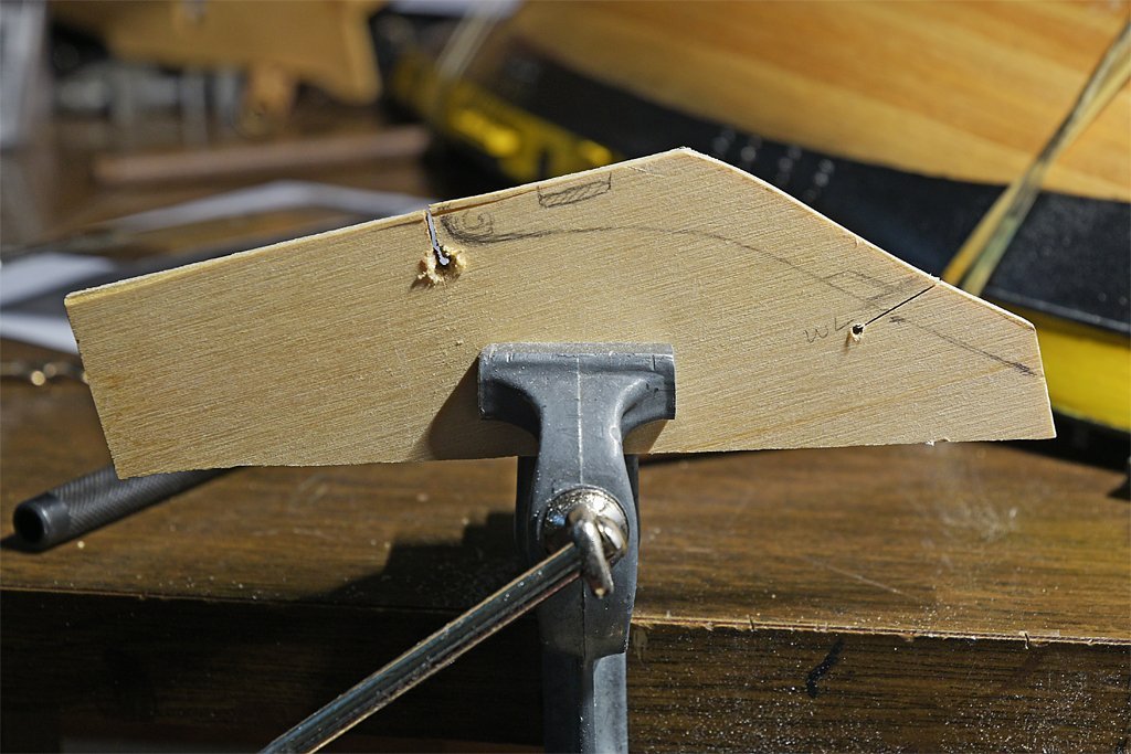
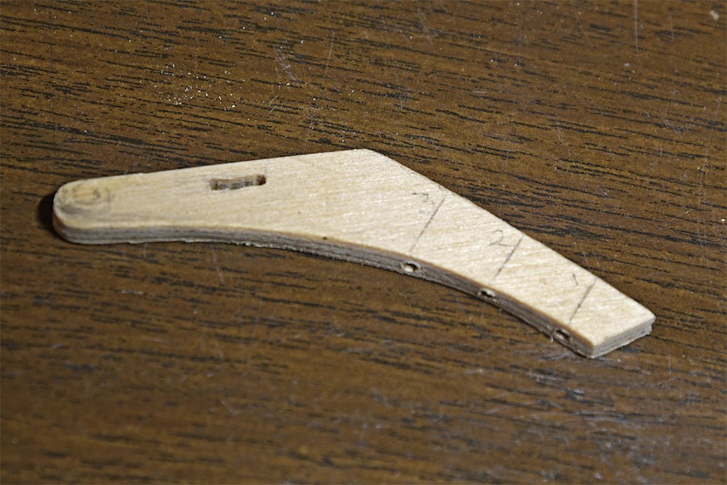
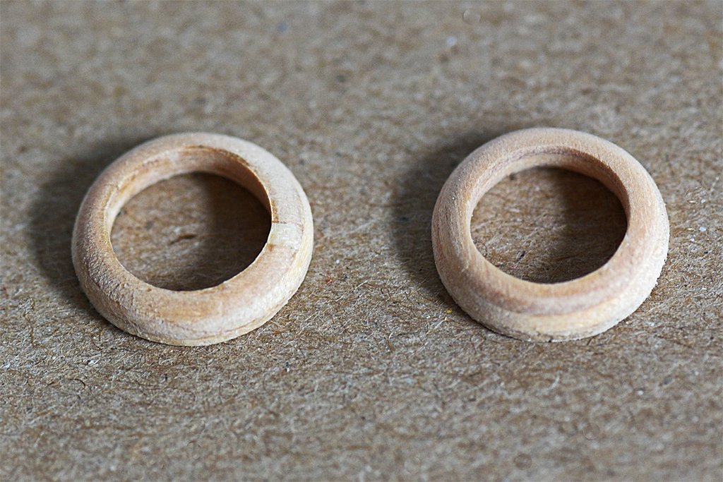
I enlarged the mounting holes in the deck and installed the masts (temporarily). I made the mast coats to fit around the bases of the masts. These things were quite a challenge! They are 0.5 inch (12.7 mm) diameter. I figured if I tried to make them from an ordinary sheet of wood they would break apart while I was shaping them. So I decided to use 1/8 inch (3.2mm) plywood, hoping the cross grains would hold them together. I picked a piece out of my scrap box, and I have no idea how old it was. But in hindsight it could have been left over from a kit from the 1960s. That stuff wasn't very good plywood to begin with, and the glue they used to hold the laminations together was pretty poor. I think the wood was holding the glue together. Again and again pieces of the outer layers chipped off and I had to recover them and glue (Duco Cement) them back on. In some cases the pieces went to never never land and I had to strip a bit of a layer from scrap plywood, shape it and glue it in place. You can see one of these patches in the left hand part. But as you can see I eventually got the parts shaped suitably. I will seal them and paint with the same brown as the bulwarks.

-
Problem creating new posts
Dr PR replied to Dr PR's topic in Using the MSW forum - **NO MODELING CONTENT IN THIS SUB-FORUM**
I can't delete all cookies (too many bank account logins, IRS and other government links, plus forums and other sites that I use regularly) but I just went through the very long list and deleted most of them. I just made a test post on the Albatros thread and it worked. It was very strange that the problem was only on that single thread. Thanks. -
Recently I have been having a problem creating new additions to my Albatros thread. When I click in the "Reply" box nothing I type appears there. Instead the "Drag files here to attach ..." is all I see. I have tried saving the new entry and opening it again, but all I see is the "drag files ..." box. The only way I have been able to start a new entry is to load some pictures and select one. After this I can add text after the photo, but there seems to be no way to go to the start of the post. So I save the new post, open it again, add text after the picture and then delete the picture. This puts my text at the start of the post. After this I can add more text and pictures. This started happening about a week ago and has happened several times now. I do not have a problem adding new posts in other threads on the Forum.
-
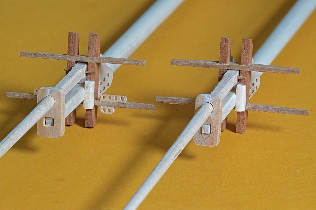
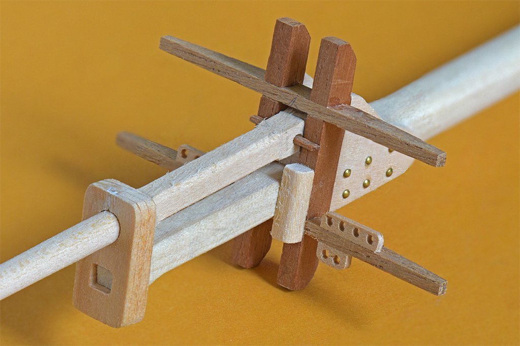
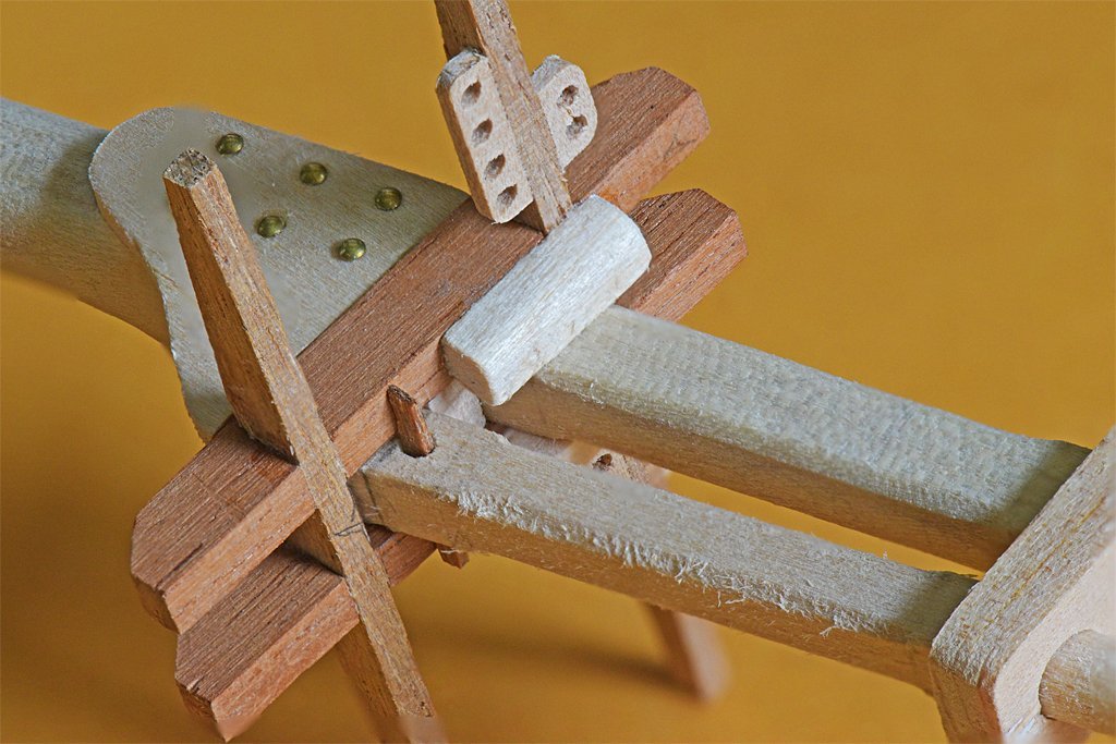
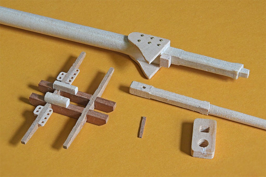
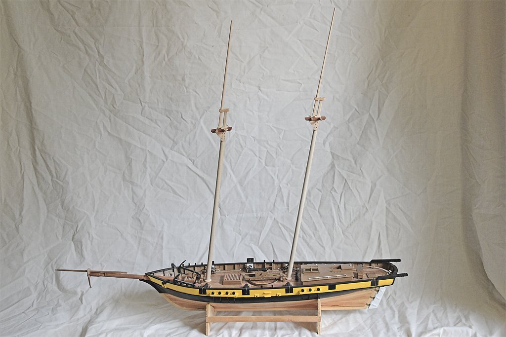
Here is a bit more progress. I have made all of the wooden parts of the mast tops and trimmed everything to fit. All parts need sealer and sanding. Above the cheeks on the mast head is a spacer block that is a rest for the topmast heel. The crosstree assembly has the bolsters and guides for topmast rigging. The topmast stays will be rigged to the ends of the crosstrees. The topmast lower part has been shaped and has the fid hole - the fid is the small piece of wood. The mast cap has a snug fit on the top of the lower mast tenon and a loose fit for the topmast. The parts of the fore top are shown on the left. The main mast (right) doesn't have a square topsail so the rigging is much simpler and the guides for the rigging aren't needed. The topmast slips into the crosstree assembly from below and then passes through the hole in the top. After the mast is full up the fid is inserted to hold it in place. This is how the real topmasts worked. I haven't cut the slot for the sheave for the uphaul rope. Also missing are bunch of ring bolts for all the stays and tackles that attached to the tops. I should have created a 3D CAD model before moving on to cutting wood. There are a couple of less than perfect parts. The bolsters are too beefy. This is basically because the trestletrees are probably a bit too wide, but they are still within the extreme ranges of the calculations mentioned a few posts above. I think I will file the bolsters to remove some material from the tops. The other problem is the position of the guides for the topmast rigging on the fore mast. These allow routing the topsail running rigging clear of other rigging to ensure the lines do not foul other rigging. The guides are very close to the trestletrees, and the lower mast shrouds have to pass between them and the trestletrees. Fortunately there aren't a lot of shrouds (three per side on the fore mast plus the fore tackle/burtoning tackle. The clearances between the shrouds and running rigging looked good on the 2D drawings. I may have to move the guides, and that could be tricky. I was surprised that I could make the tiny pieces without them breaking apart when I drilled the holes. The holes are 0.057 inch (1.4 mm) diameter on 0.1 inch (2.54 mm) spacing.