Mirabell61
-
Posts
7,421 -
Joined
-
Last visited
Content Type
Profiles
Forums
Gallery
Events
Everything posted by Mirabell61
-
 Pete, you mentioned that you understand German, here is an interesting document for your evaluation phase, if you wish.... for Zeesboot rating.... https://www.braune-segel.de/pdf/klassenvorschriften.pdf Nils
 -
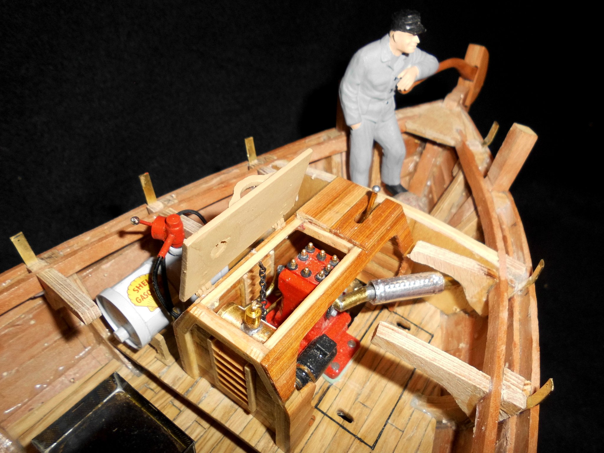
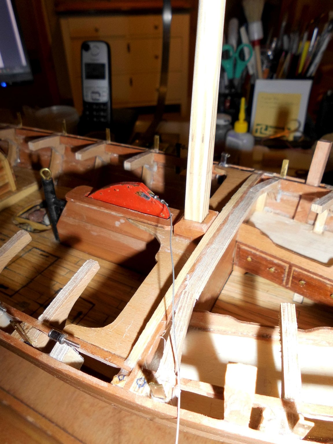
Good morning Pete, all that you see on the 3 forstanding pics is only for the plug function and will be removed after clinker planking. Keel and posts are made from pear wood, pls. refer to my post #37 the keel, the bow- and sternpost are screwed down on the plug, and not glued, as they will be permanently glued to the pear keel and the pear clinker-plank ends. The individual clinker planks are also horizontaly glued together. In my case some of the glue spillt on to the plug. The intension was to easy remove the plug completely from the shell, just by loostening the mini screws of keel anf the two posts. The plug was sitting too tight, due to spillt and cured glue, so it unfortunately had to be cut out of the shell carefully in some places ( being a "one way plug"). This could have been avoided by putting some transparent tape on the outer bulkhead contours of the plug, before planking. Nils
-
Good morning Pete, thanks for your compliment to the scetches. Most times whilst I do them there come ideas for further impovement.... A pitty your book got damaged, but trust it will still be of great help for you. I`ve just done the two masts for mine yesterday, shaved them frome sqare to octogonal and then rounded an tapered a bit. The 3/4 mizzen can be layed flat The harnesses for the deadeyes are done and blackened, and I still have some Morope for shrouds and laceings.. It would be better, if the deck is started now Nils mizzen layed down main mast from 8 mm square, mizzen from 6 mm square


- 401 replies
-
- 18
-

-
Wow !! A great build Karl Nils
-
kit review 1:72 Tender ‘Avos’ (XS Edition) - Master Korabel
Mirabell61 replied to James H's topic in REVIEWS: Model kits
Masterly built from a extraordinary designed kit Nils -
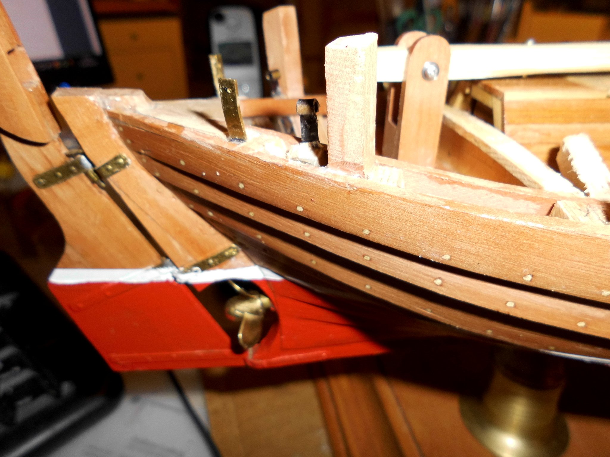
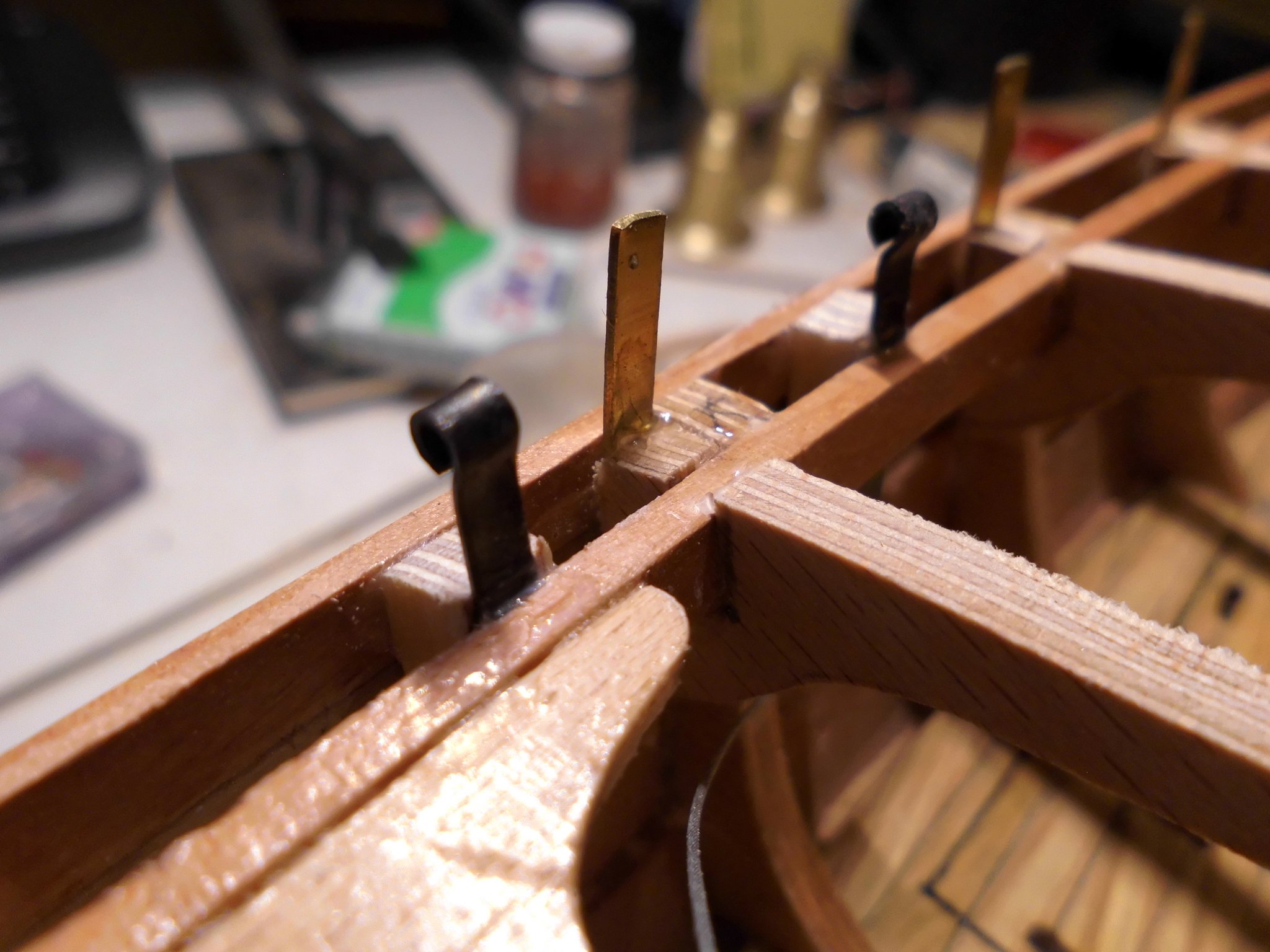
Good work B.E. I knew youre going to master it , great looking ! In the meantime ( my Zeesboot) I drilled 0,6 mm holes for the horizontal plank connections, widened them to 1 mm, and glued (carefully knocked in) the points of bamboo toothpicks into the holes with low viscos CA wetting. After trimming and flush sanding it now looks as if all thes connectors have been plugged off with wooden plugs Nils
- 335 replies
-
- 1
-
-
- alert
- vanguard models
- (and 1 more)
-
Hello Geert, congrats, I know its an exiting moment, when the shell is removed from the mold, now you certainly will be starting with the framework..... Nils
-
Hi Piet, All my build logs of the last years are linked to my signature..., the last was the Chebec "Eagle of Algier" Cheers, Nils
- 378 replies
-
- 4
-
-
- java
- pacific crossroads
- (and 2 more)
-
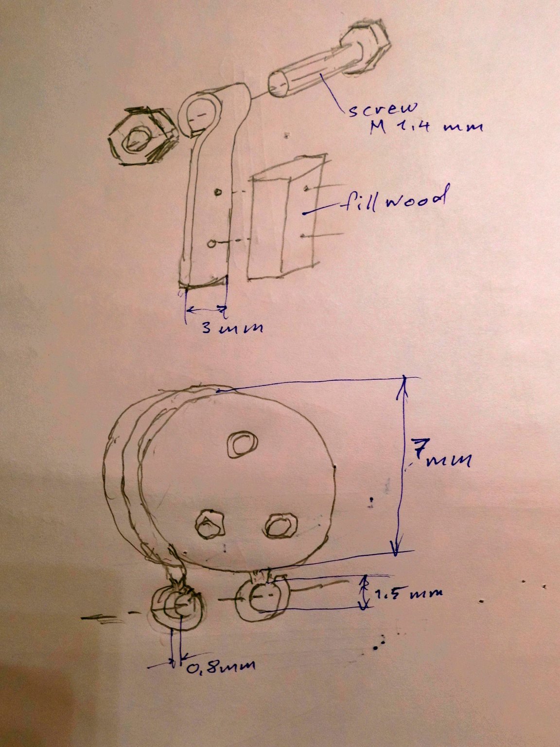
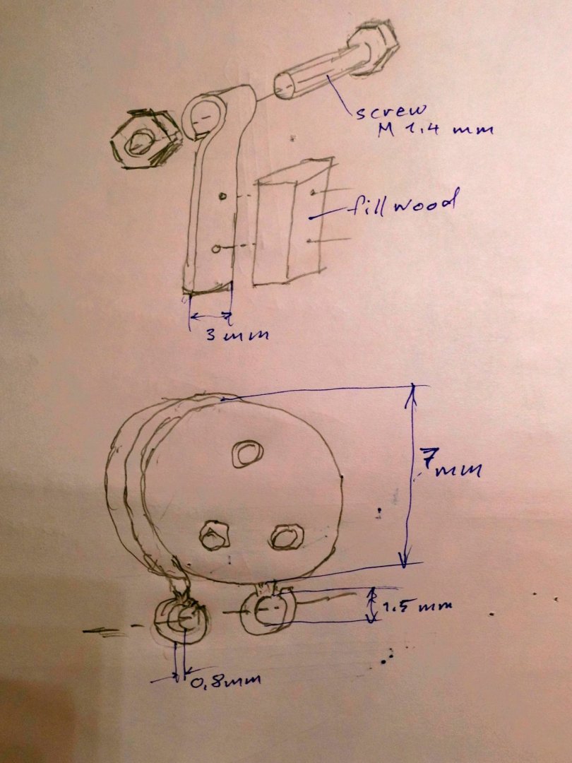
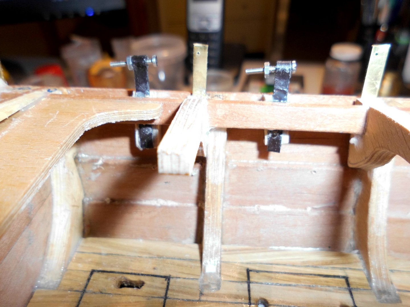
Fastening points for mainmast deadeyes : two shrouds at both sides are spaned with laced diam. 7 mm deadeye tackles near to the deck. The fastening points are made from 3 x 0,6 mm brass flatt (chem. blackened) with a loop for the screw that goes through the looped endes of the deadeye harness..... Nils Handscetch (not scaled ! )

- 401 replies
-
- 11
-
-
Good morning Piet, thanks for looking in, and much fun when exploring the build log.. Nils
-
Piet, your plexiglass display case looks great ! Nils
- 378 replies
-
- 5
-
-
- java
- pacific crossroads
- (and 2 more)
-
Pete, thanks for posting that video, its fun to watch the little boat on the lake... Nils
-
Cute lttle boats Pete ! realy something for inbetween.... BTW, I see those arrows standing on your desk, are they for a crossbow ? Nils
-
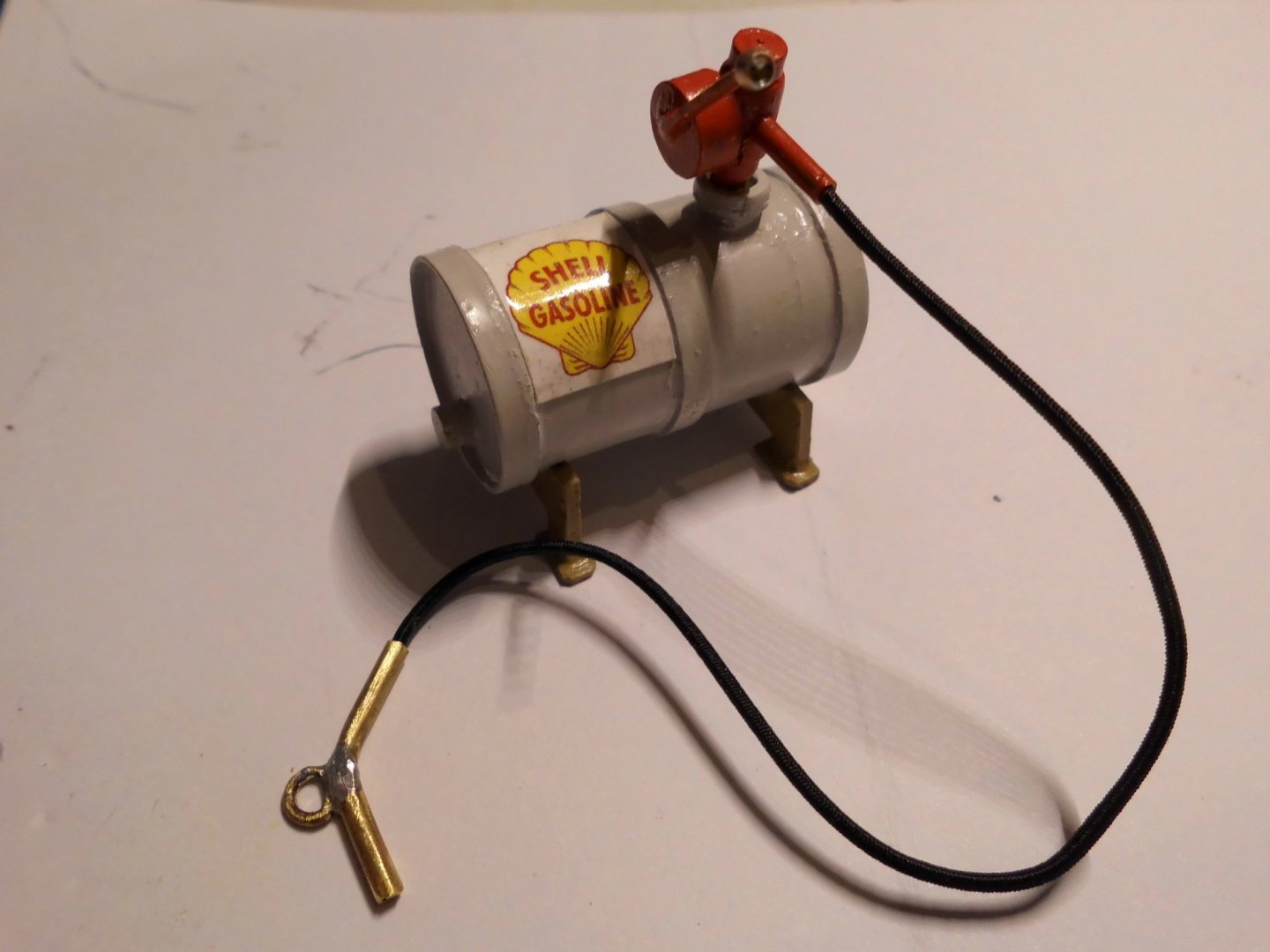
This is the outcome for for an utmost flexible and black rubber hose (received today), trust this will do much better than the PVC one.. Nils
- 401 replies
-
- 19
-
-
Unglaublich schöne Arbeit Johann, incredible work !!! Nils
-
Hello Geert, yes , they surely would also fit very well to the Zeesboot, I`ll evaluate that when it comes to the rigging.. Nils
-
Thank you very much Mustafa, and for looking into the build log... I had a look at your Santa Maria, coming very nicely.... Nils
-
Very nice block making Geert ! Nils