


Ras Ambrioso
-
Posts
594 -
Joined
-
Last visited
Content Type
Profiles
Forums
Gallery
Events
Posts posted by Ras Ambrioso
-
-
-
Wefalk, thanks for the effort and the information. I went to the Overton museum site and I found a tiny picture (thumbnail) of the type of engine arrangement similar of what I need. Since I am not building this model for a museum or for historical accuracy I am going to go with a "representation" of what I think the engines would have looked like.The thumbnail I found follows
.
Very similar with the arrangement I have seen. Thanks again.
- Roger Pellett, GrandpaPhil and mtaylor
-
 3
3
-
Looking forward to your jolly boat. I had a hard time making mine for Amapá at almost twice you scale.
- Keith Black, mtaylor, mbp521 and 1 other
-
4
-
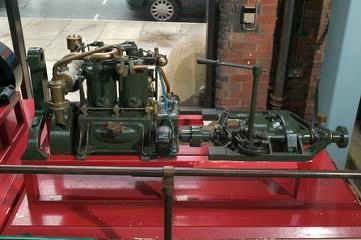
Wefalck, I miss your comments and your amazing knowledge of the history of these ships. I am working on Amapá internal structure and found differences between the molded hull that I bought and the plans of the actual boat. Right now I am fabricating the two petrol engines. Unfortunately, I have found very little information on the actual engines installed in the boat. In my searches on google the closet thing I found is the following
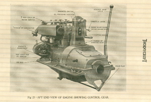
So I am now working to replicate it (somewhere within my tolerance). Most of the Thornycroft information I found is for diesel engines and essentially later engines. If you have any better data let me know. I am trying to figure out the actual controls from the helm.
- GrandpaPhil, mtaylor and G.L.
-
3
-
Your work is amazing, please be careful and stay safe.
- shipman, FriedClams, Keith Black and 3 others
-
5
-
 1
1
-
-
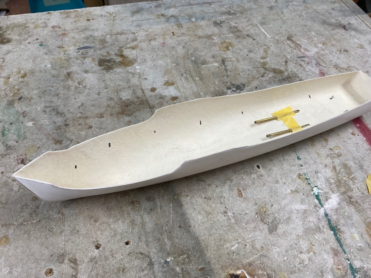
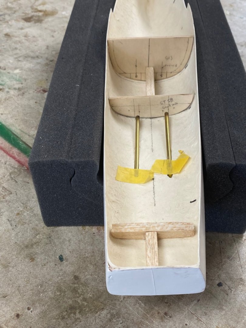
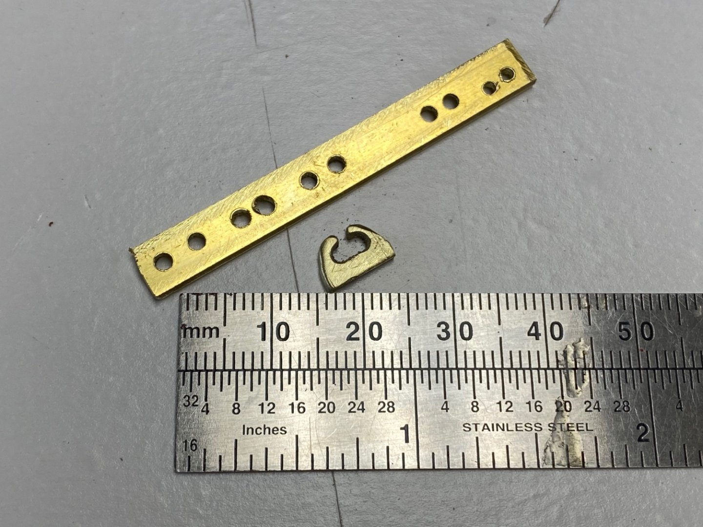
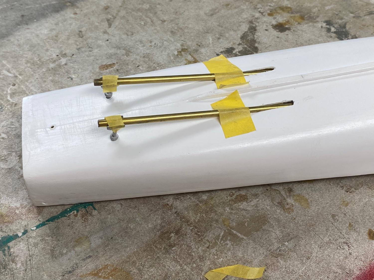
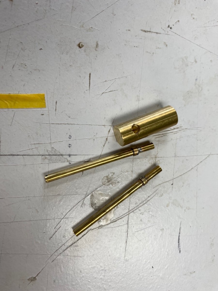
The cradle is finished and I started the fabrication of the propellers support brackets. These were furnished in the kit, but they are kind of rough so I am going to reproduce them in brass. But then I realized I had to set the shafts first to see the layout and get the right angle on the supporting shafts. Following is the dry fit of the shafts using the white metal fittings

Started the fabrication of the supports after measuring the actual angle of the shafts and these are the parts.

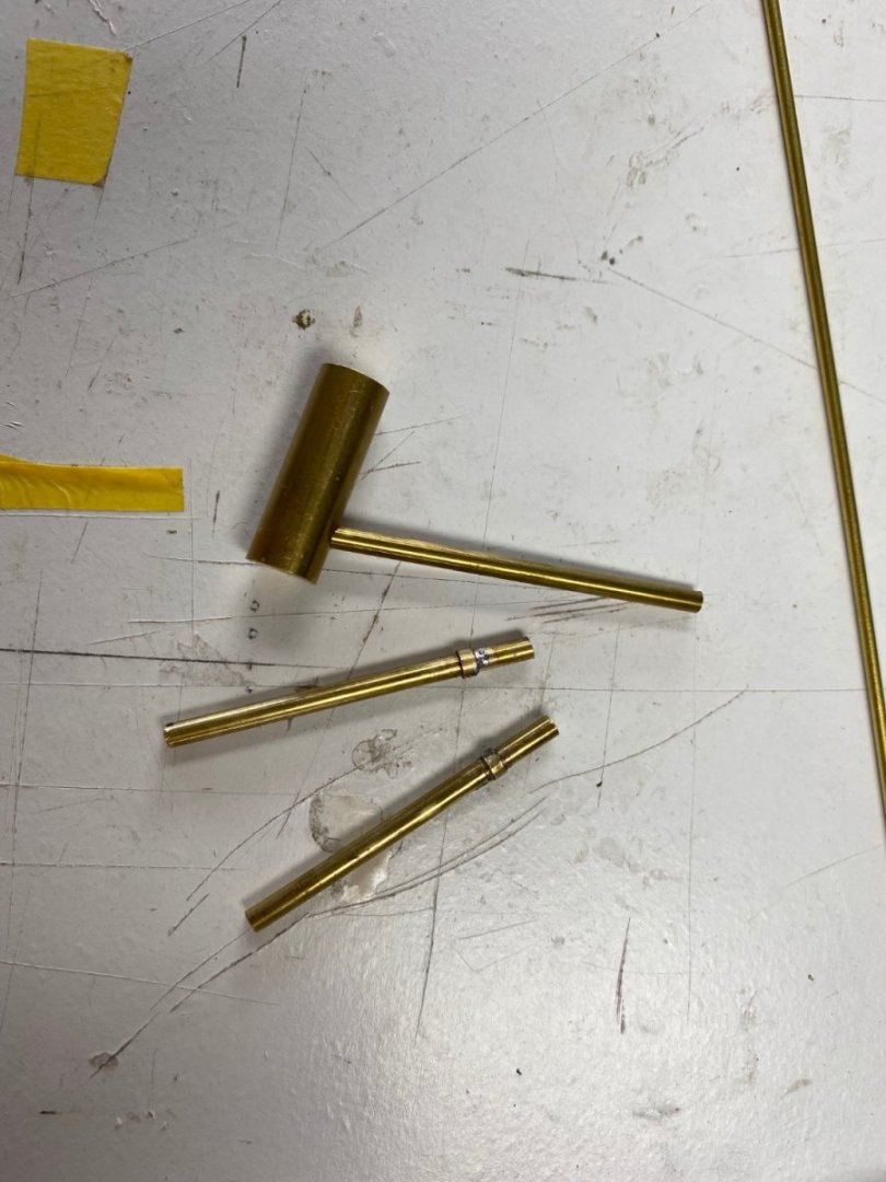
Then, I set up my Unimat lathe to reduce the part of the exposed shaft and tragedy ensued. After I finished the first shaft my 3 jaw chuck locked up and I couldn't get the piece out of the chuck.
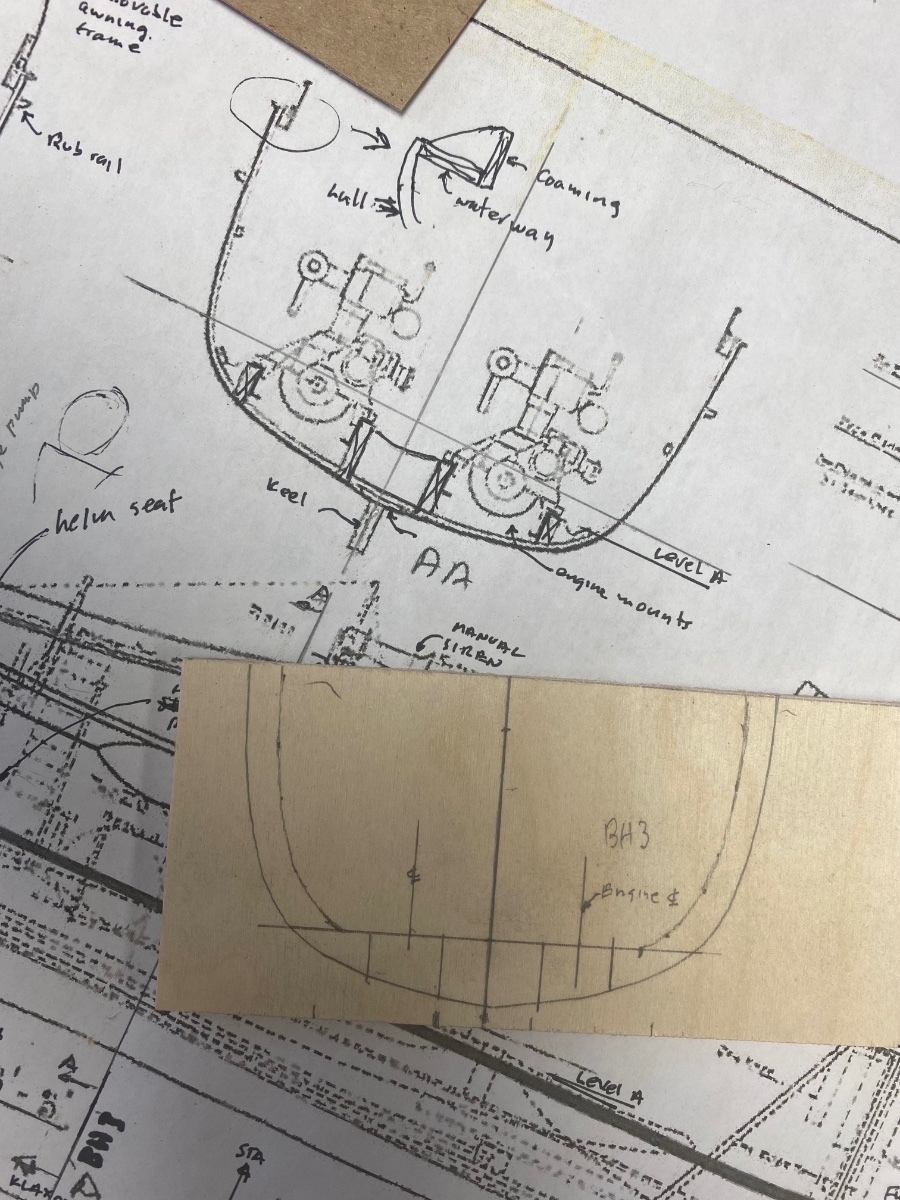
I decided to proceed with the build by fabricating the hull frames that will fill the empty hull. For these I used the only plan that I have available (see my post #1).

Then I found that the Dean's hull actually does not totally match the original plans of this vessel so I have been making templates until I got the right layout.
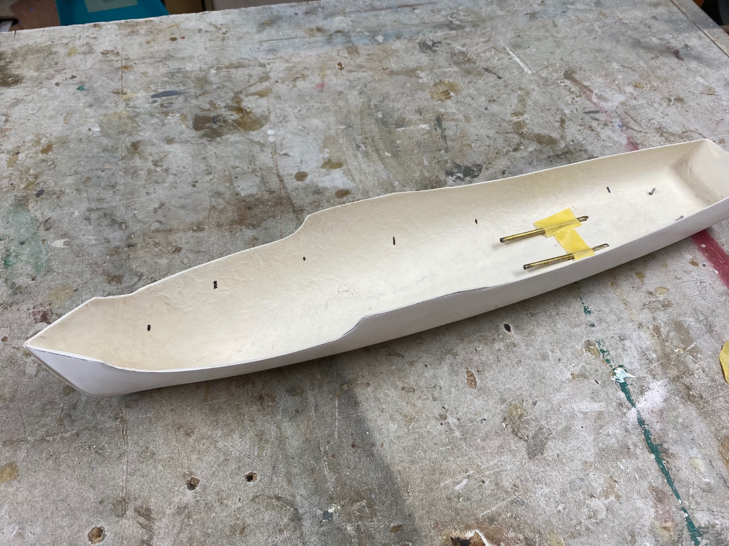
I also reinforced the thin hull where the propeller supports and the rudder will be installed.
Then, one of my neighbors helped me with the unlocking my 3 jaw chuck and I will be back in business tomorrow. 👍
-
Thanks guys, I really appreciate your comments and, as I have said before, I couldn't have done it without you support and information. I have been building models since I was 8 years old, now I am 86 years old and still learning skills in this magnificent hobby.
Now I am embarking in another challenge building HMS Mimi and I hope you keep me in line.
Thanks
- Paul Le Wol and mtaylor
-
2
-
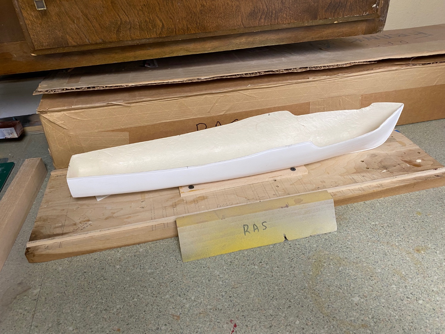
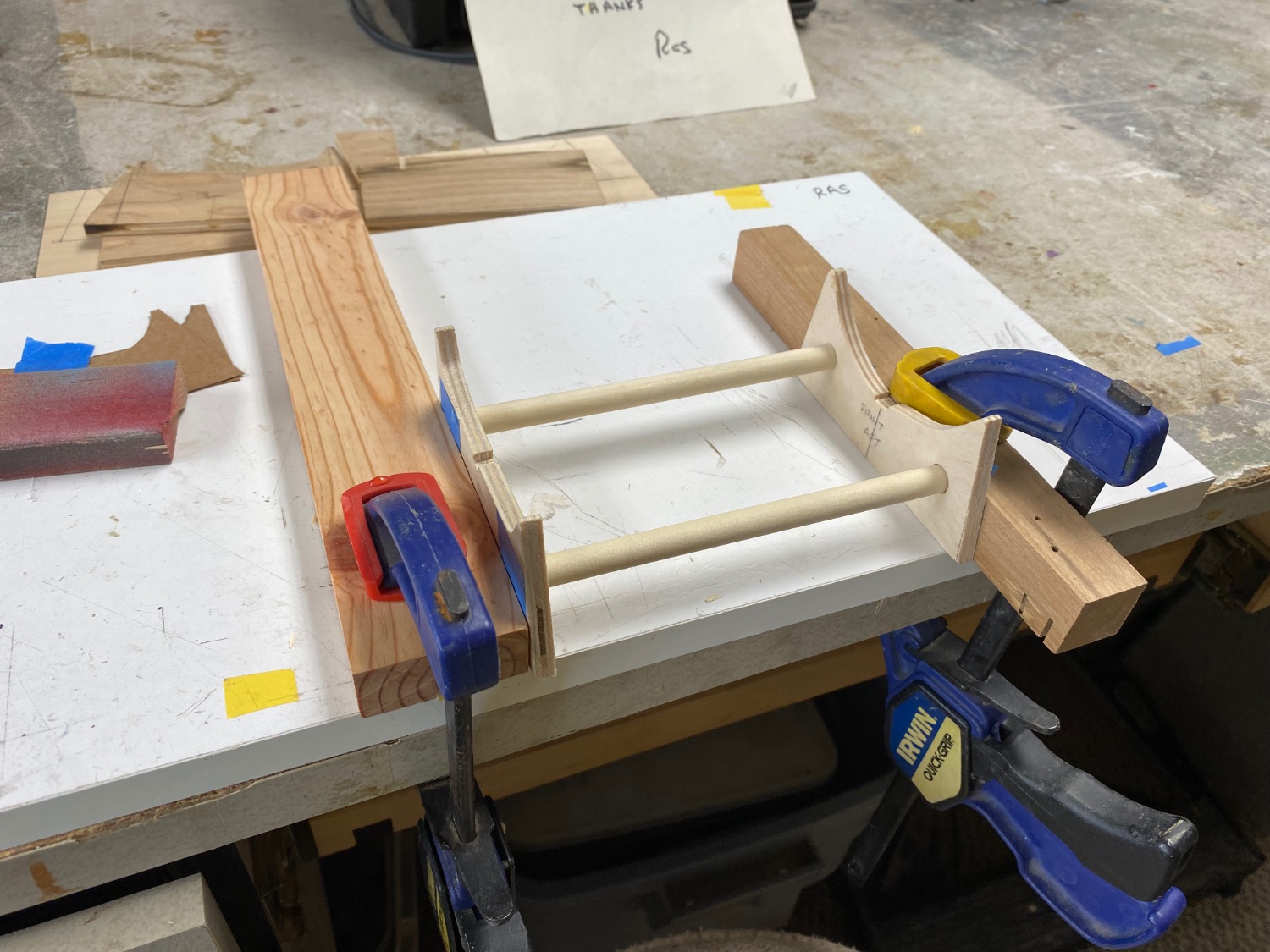
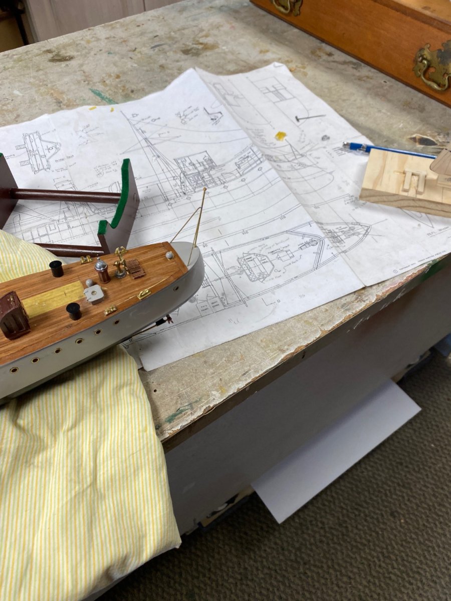
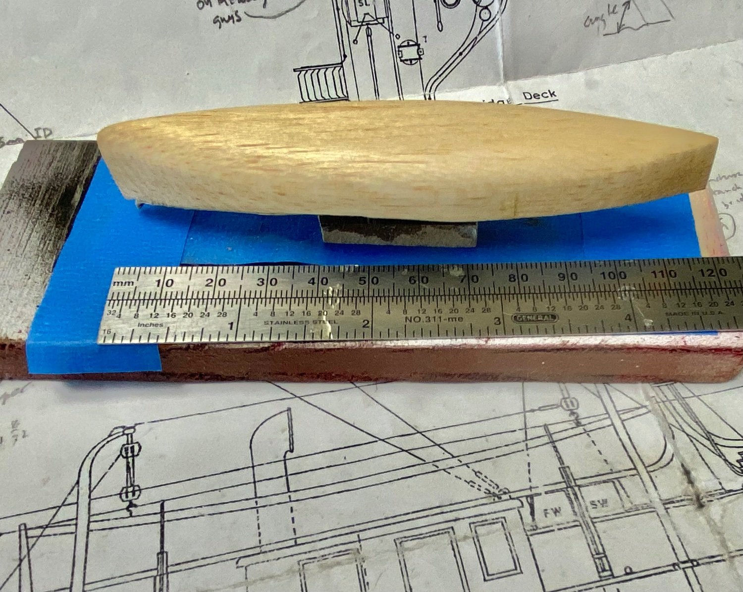
Well guys, Amapá is finished and now is resting on display at the lobby my building. So, it is time to start building Mimi. The first thing was to clean the hull to remove the mold waxes. Then I started fabricating the hull cradle.
This is Mimi in her building board:
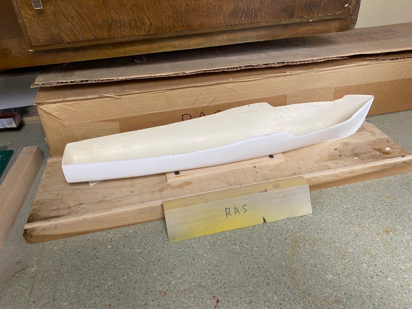
And this is the cradle drying the glue.

More to follow soon.
- Paul Le Wol, mtaylor, GrandpaPhil and 3 others
-
6
-
-
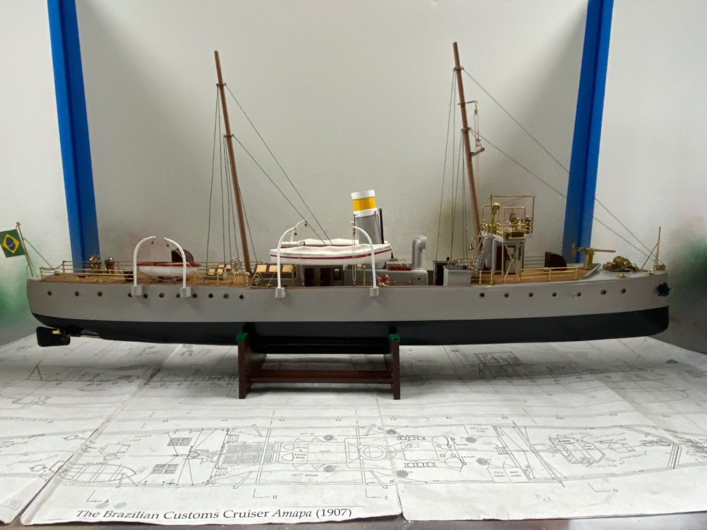
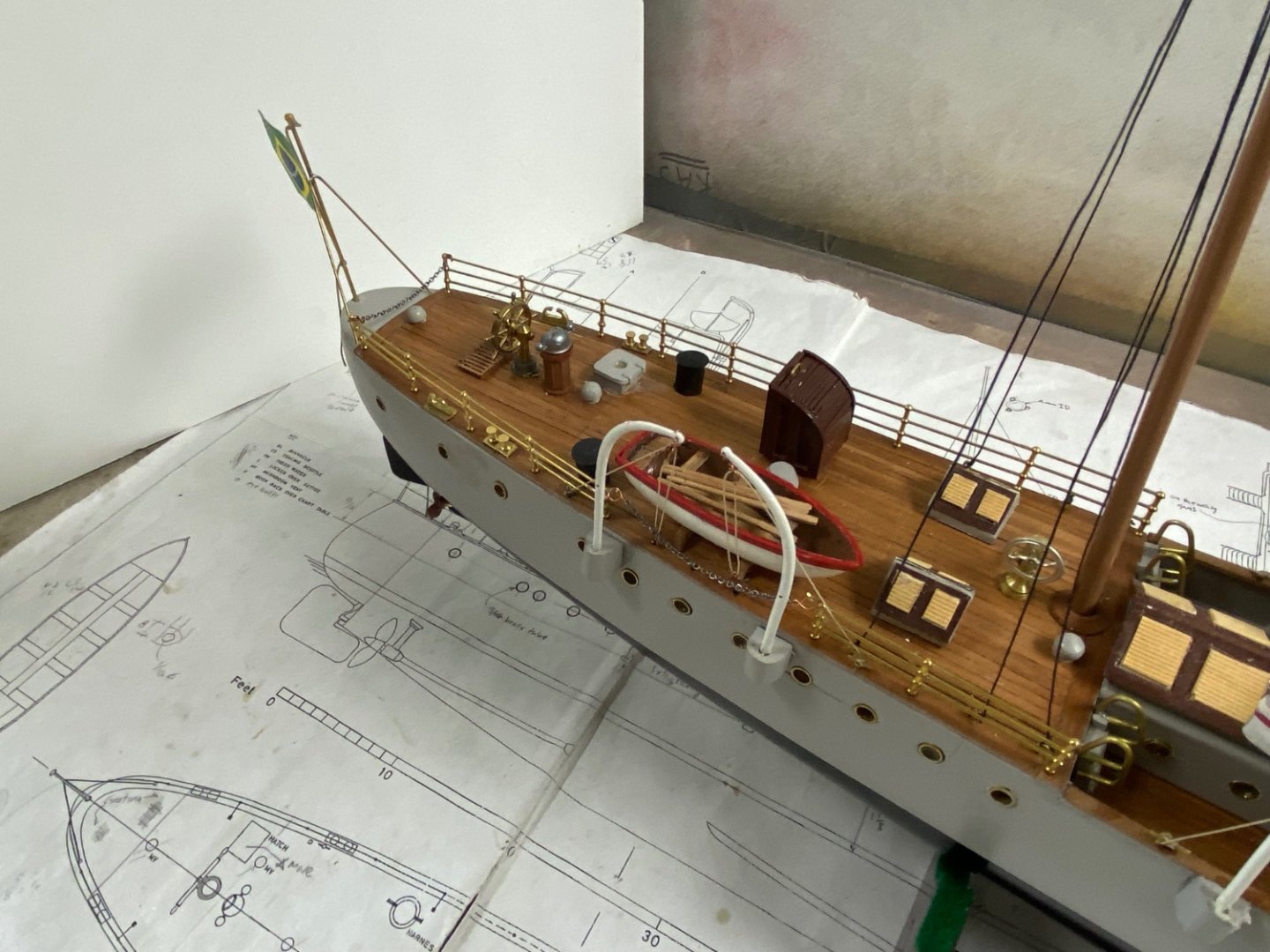
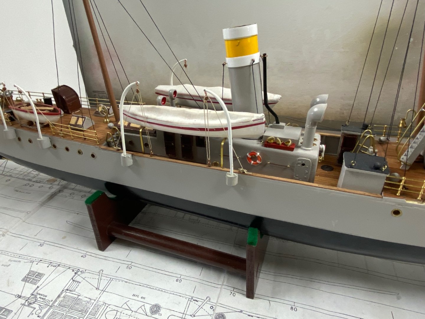
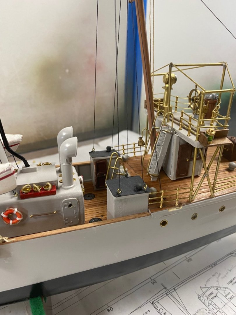
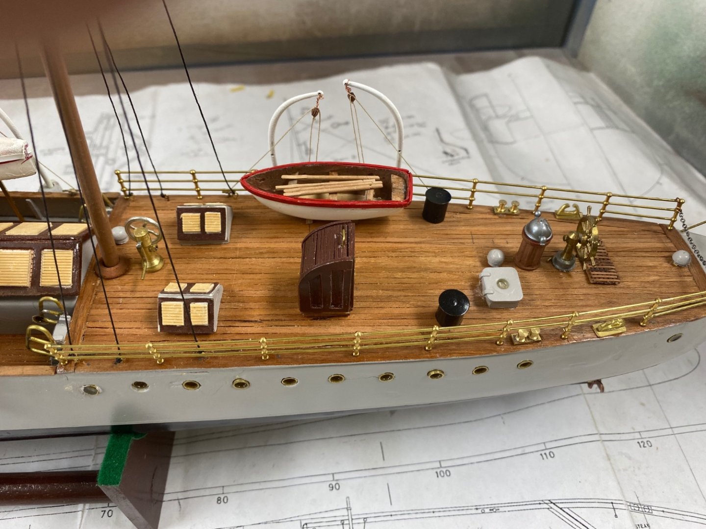
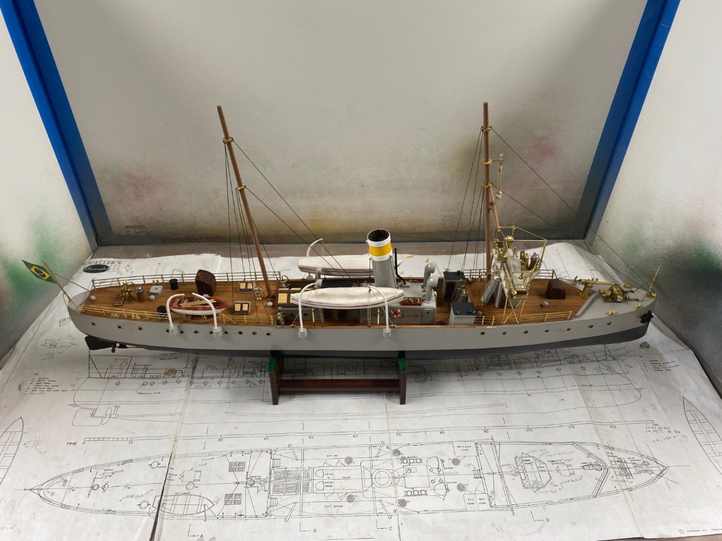
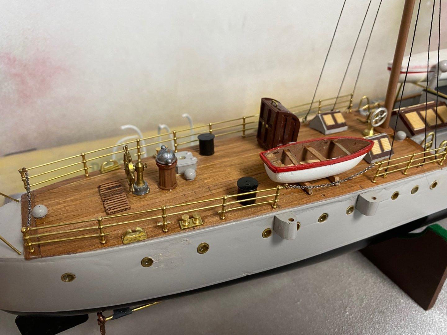
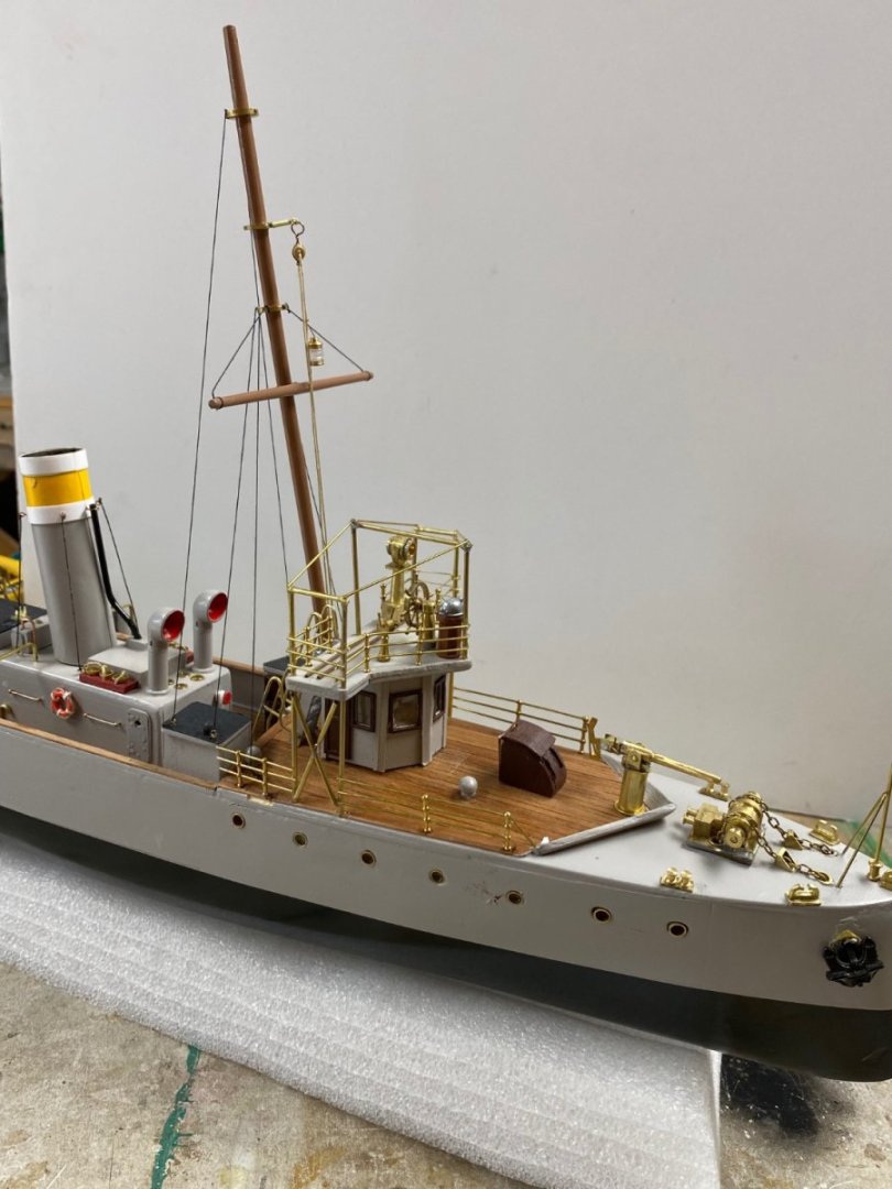
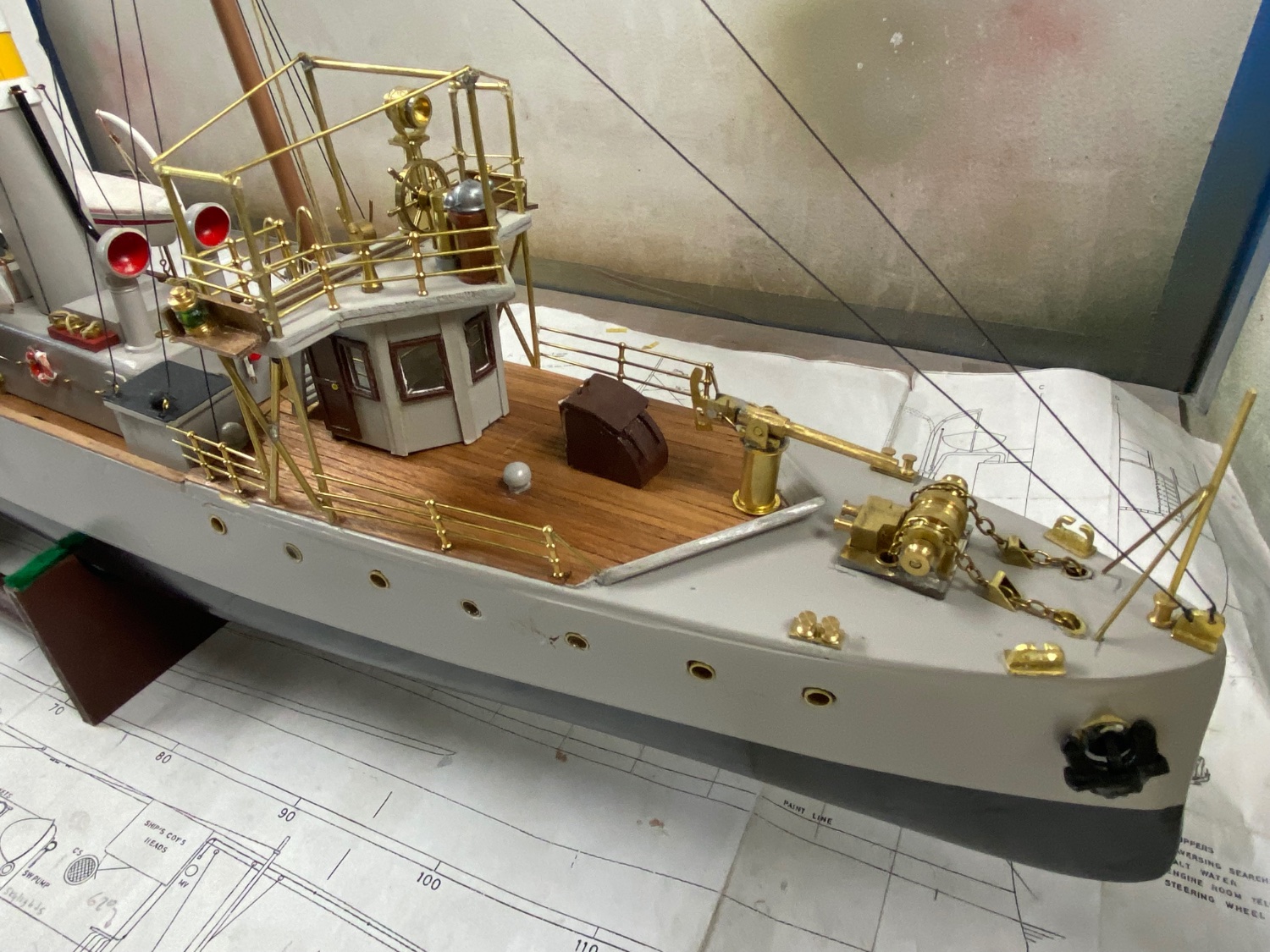
Following are the photos of the finished model.


- Ryland Craze, mcb, Harvey Golden and 11 others
-
10
-
 4
4
-
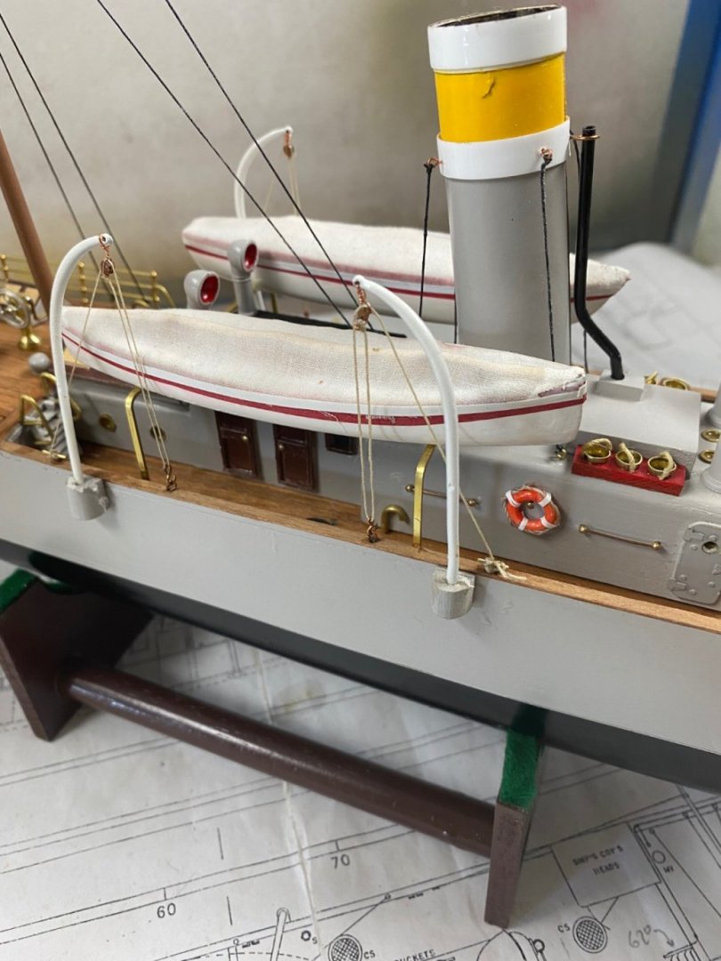
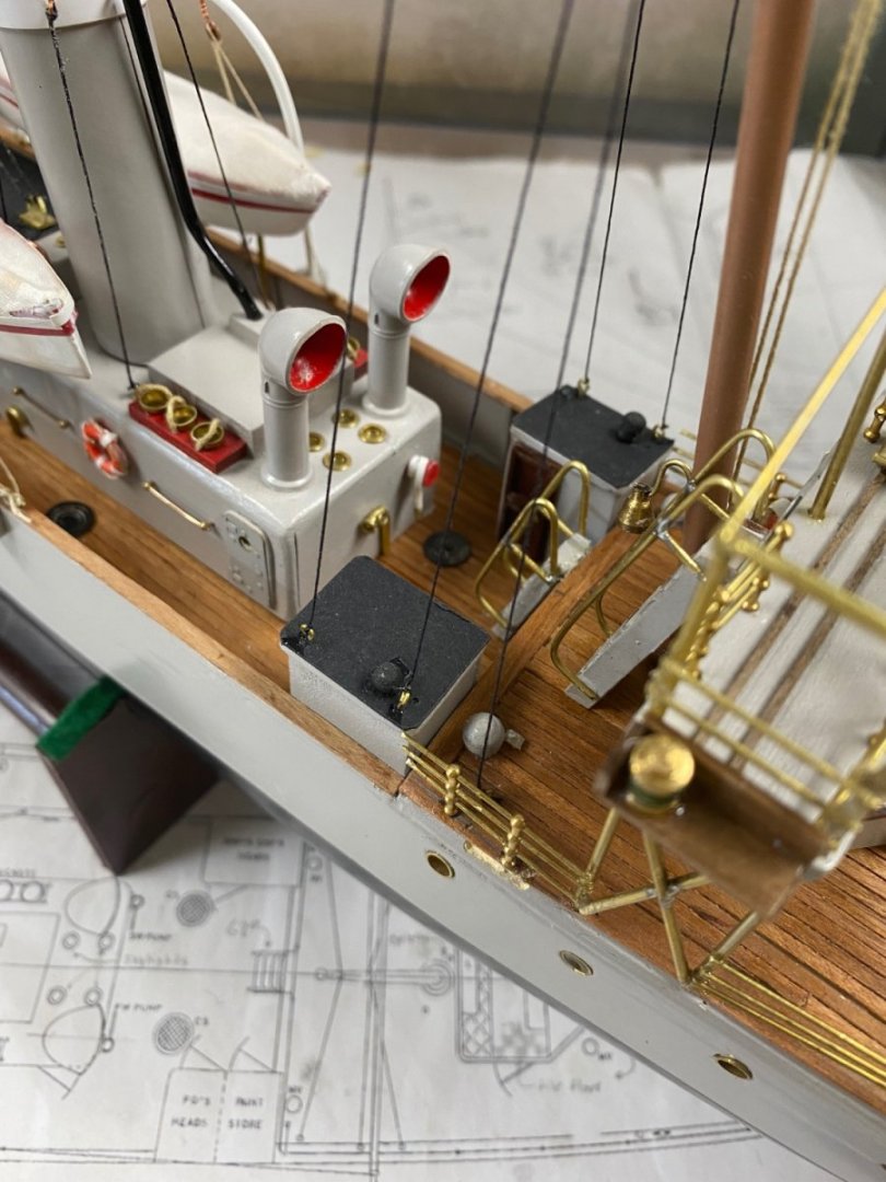
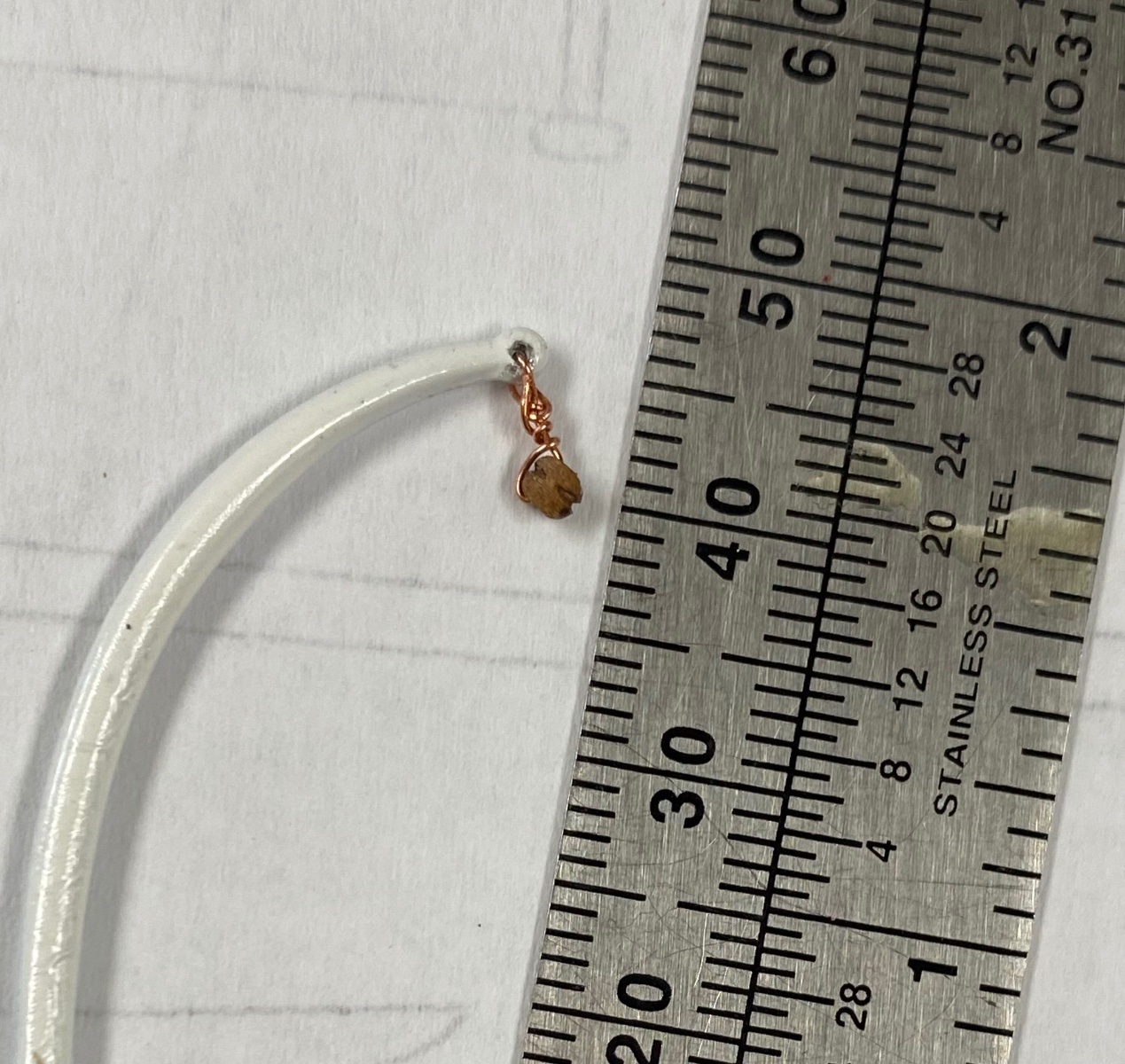
Work continues. The rigging of the davit for the small boats required a double block rig. I had purchased miniature blocks to keep the scale. These blocks were so tiny that I could not feed feed the lines through the sheave's holes. The plans called for a double line set up but I decided to simplify it to a single block. To this effect I stropped the mini block with very fine copper wire
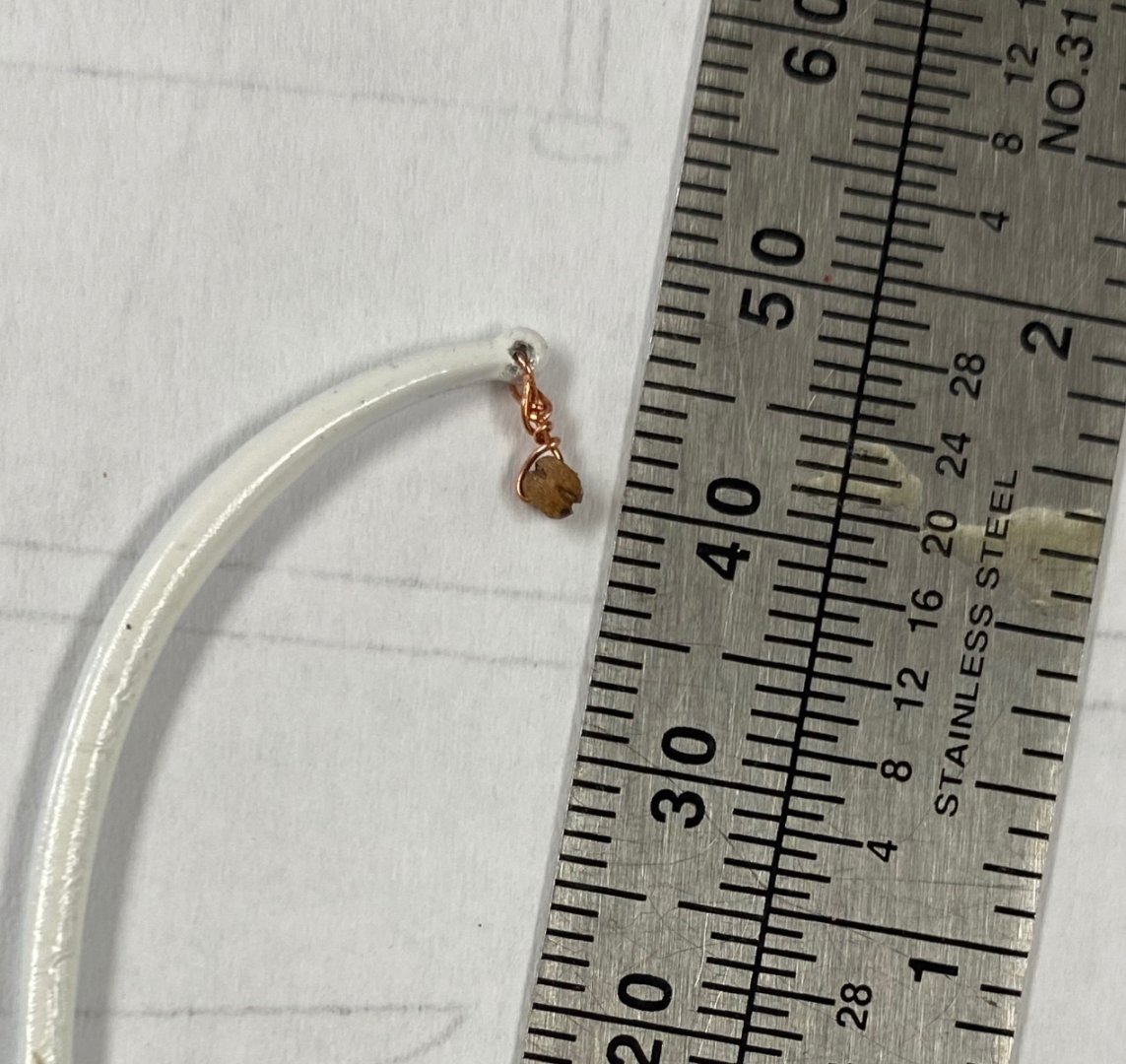
Then I made a jig to fabricate the hooks that worked perfectly
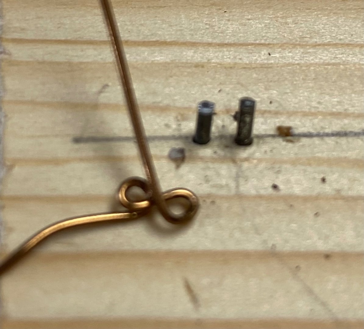
Then I fabricated miniature cleats

The results were satisfactory

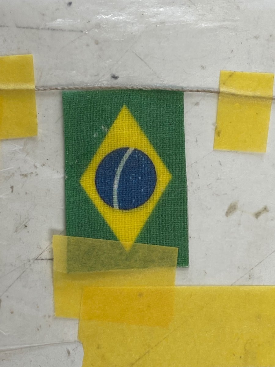
Last but not least I tried to make a decent looking Brazilian flag. I found a source that had the printed flag to the right size on a a very fine cloth (chiffon) which permitted seeing both sides of the flag. I tried several ways of making this flag to look alive but failed. Then I just just opted for the commonly shown rigid look. Please forgive me.

And that completed my presentation of the model of the Amapá, a 1907 Brazilian Customs cruiser. Following this post are the pictures that will also be posted in the gallery of finished models.
-
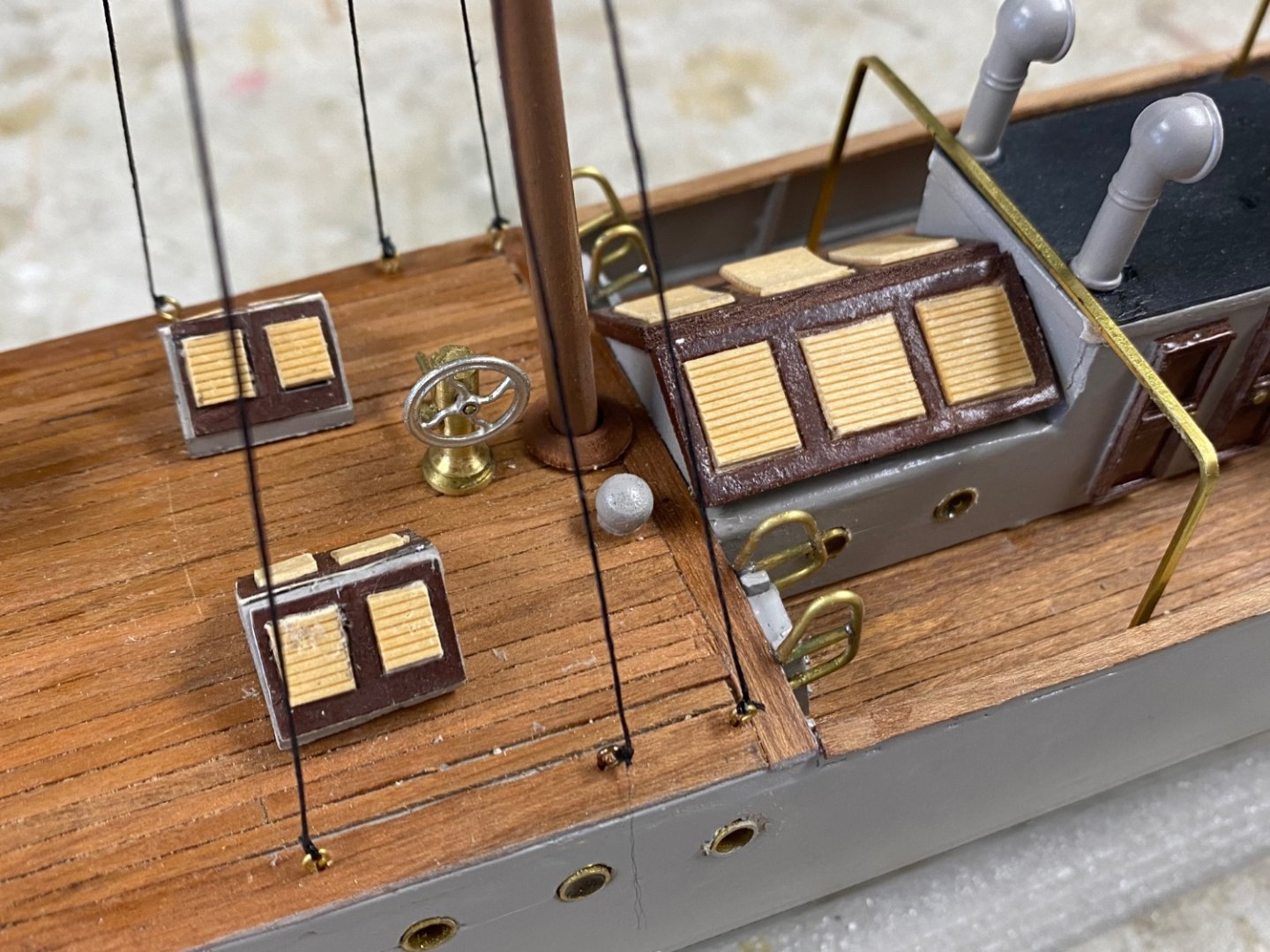
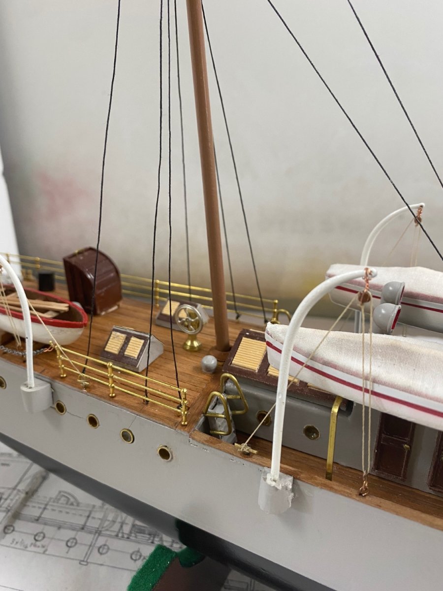
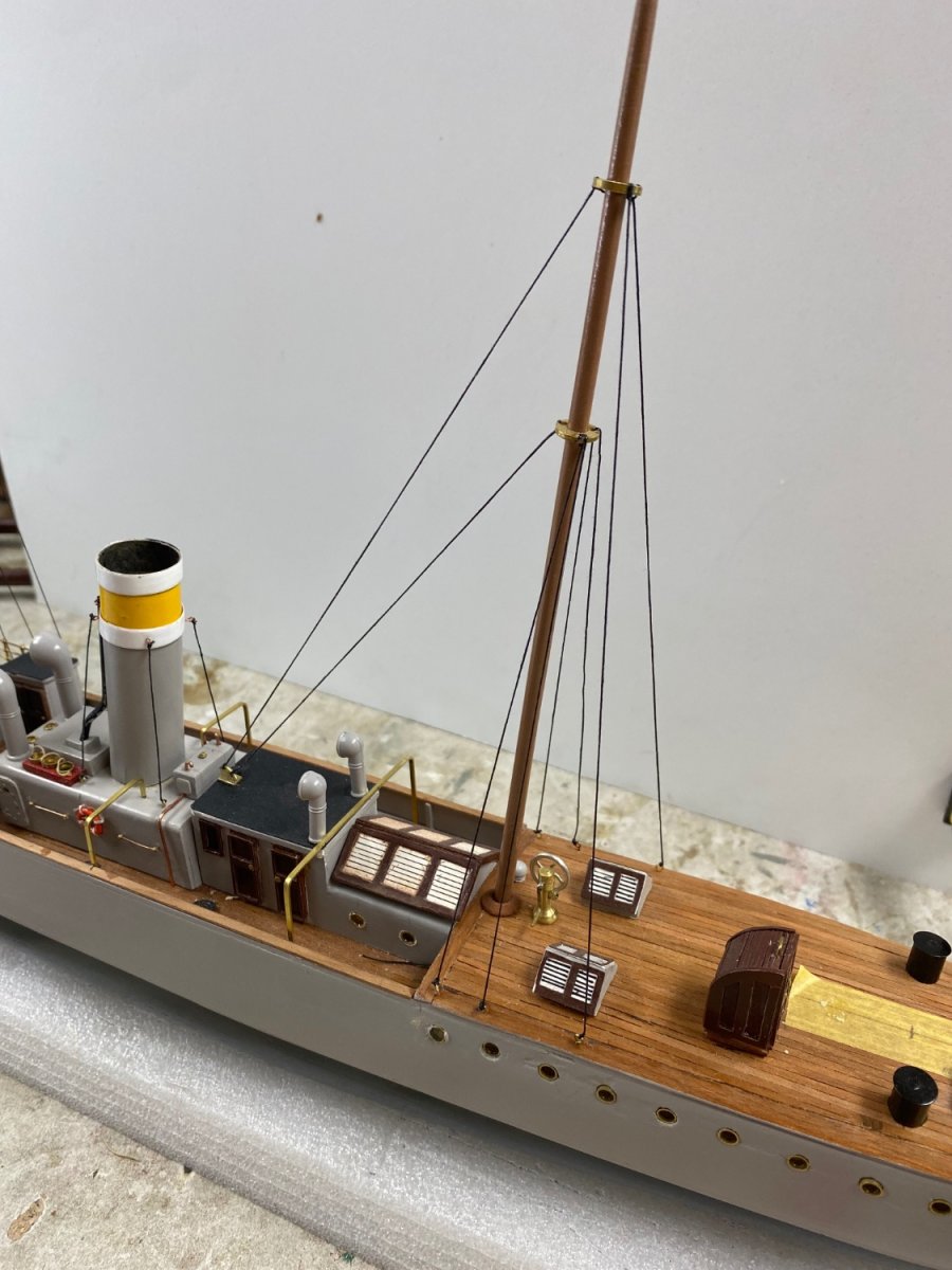
Progress continue.Previously I have worked on the louvers for the skylights on opted to simply draw them up. This was shown in my post #98. I was not very happy with this and kept searching another solution. I found it while browsing a model RR web site and found HO scale clapped siding that at my scale fit perfectly for the louvers.
And here is the latest look of the skylights
Completed the ship's boat and installed in in their respective mounts.

Also finished the stern railings
The work left is the erection and rigging of the boat's davits. For this I ordered miniature wood blocks that arrived today. They are minuscule (2mm) and I am now trying to figure out how to thread the line through them. But that is the fun of this build.
That will complete this model on time for display at the end of the month in the lobby of my building.
- Harvey Golden, wefalck, KeithAug and 6 others
-
9
-
When we think we have seen it all, you come back with an incredible answer to the small scale boat building. WOW, WOW, WOW
- lmagna, Keith Black, mtaylor and 2 others
-
5
-
I expect to complete Amapá by the end of August and get started on this project. My experiences with Amapá have given a lot more confidence in my builds and this model has the advantage of starting as a kit. I expect to have a lot of fun with it and to share it with y'all.
- Paul Le Wol and mtaylor
-
2
-
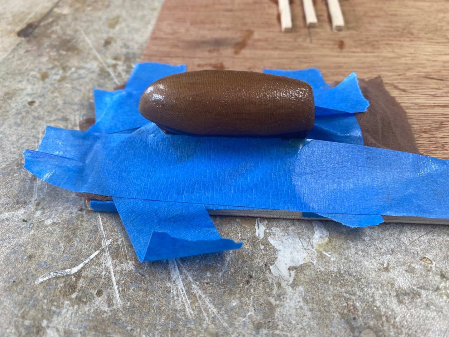
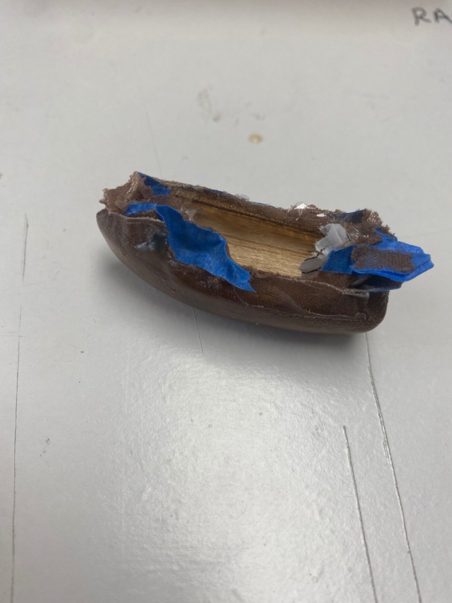
Talking about boat building, I went back to my ruined dinghy mold and refitted it for another try at resin molding. First I reworked the damaged mold.
Following Valeriy suggestion I formed the stocking under pressure using making tape. I placed a layer of resin and, while still sticky, added another layer of stocking material and resin
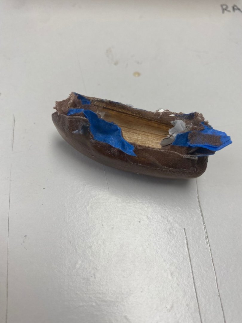
24 hours later I tried the removal of the hull from the mold.
The results a beautiful strong small hull.
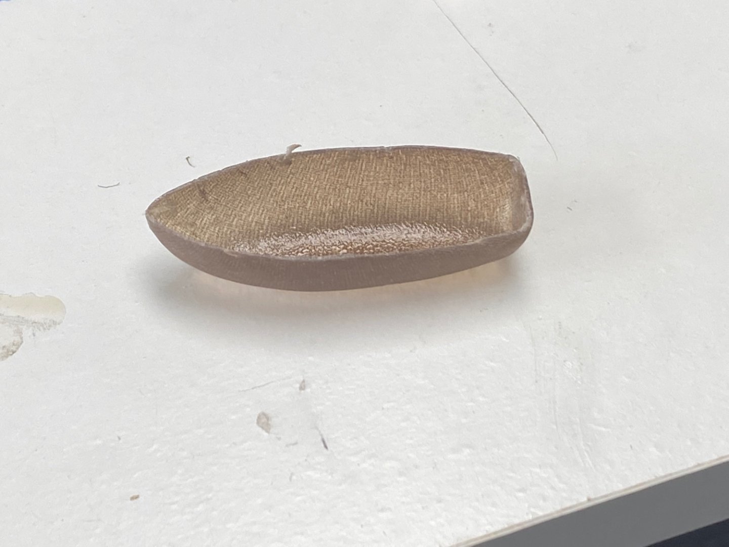
I followed all the hints and suggestions by the forum: seal the mold with lacquer, cover the mold with saran (plastic) wrap, apply the stocking material over the plastic and lock it in place under pressure. Then I applied the resin and a second layer of stocking material and resin. I am more than pleased with the results.
But, I have been advised by the art coordinator in our building that the displays in the lobby will be changed by the end of August. This will mean I will have my old Fifie back and an empty space in the display is available for new models . So, as it has been in my old career as a construction engineer, the deadline is on.
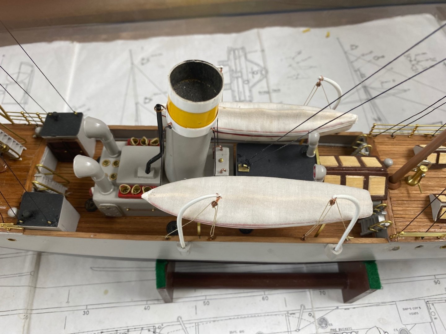
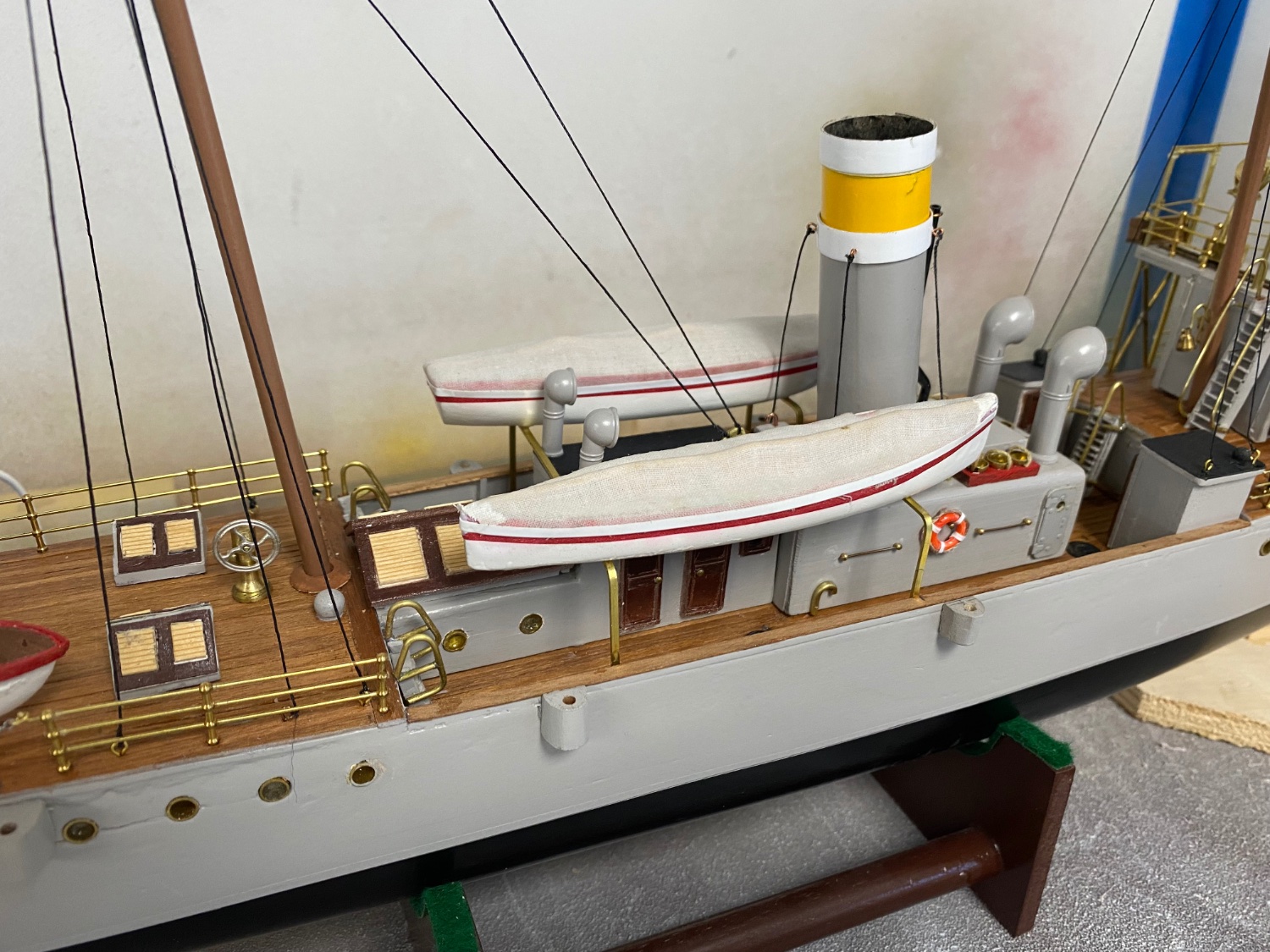
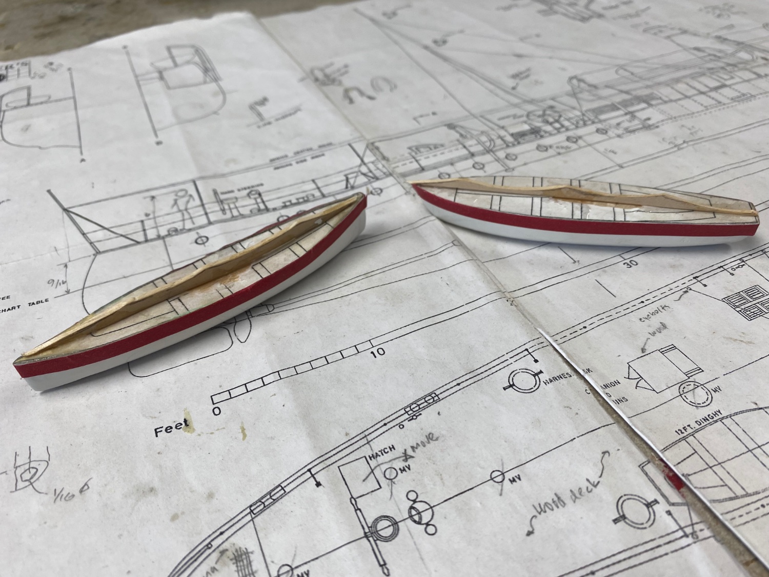
Amapá is almost finished so I decided to use the other two ship boats molds as solid models and presented them as covered boats in their respective supports.

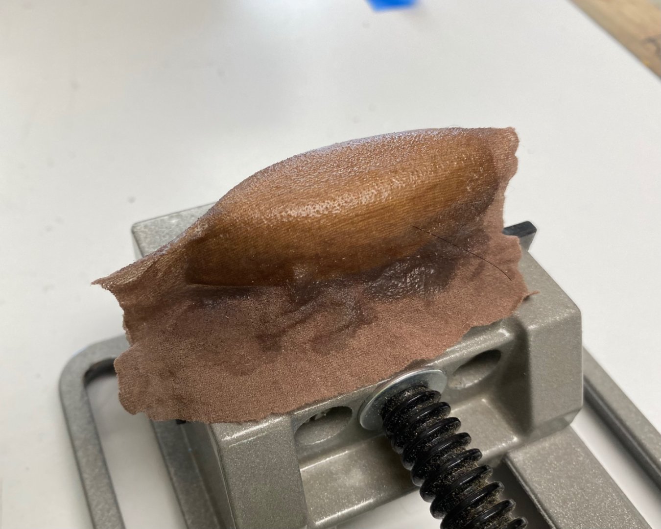
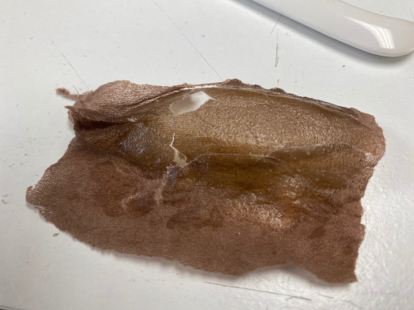
The photo shows my intent. I got a lot of suggestions for the material to use on the cover and tried the tissue with no good result. Finally, I decided to use fine linen from one of my old handkerchiefs soaked in watered down PVA glue. I will post the result shortly.
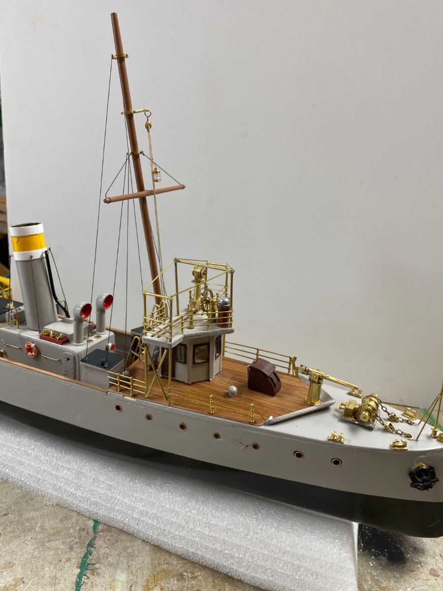
Continuing with the build, I completed the standing rigging on the mizzen mast.
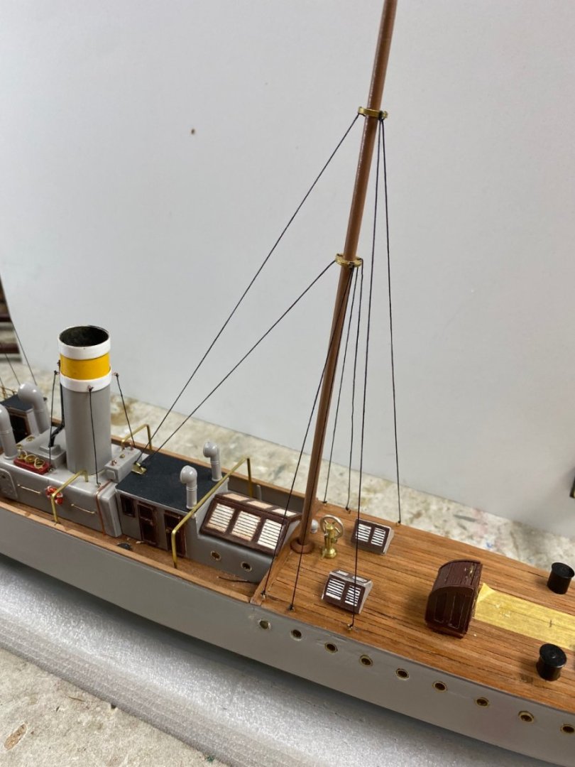
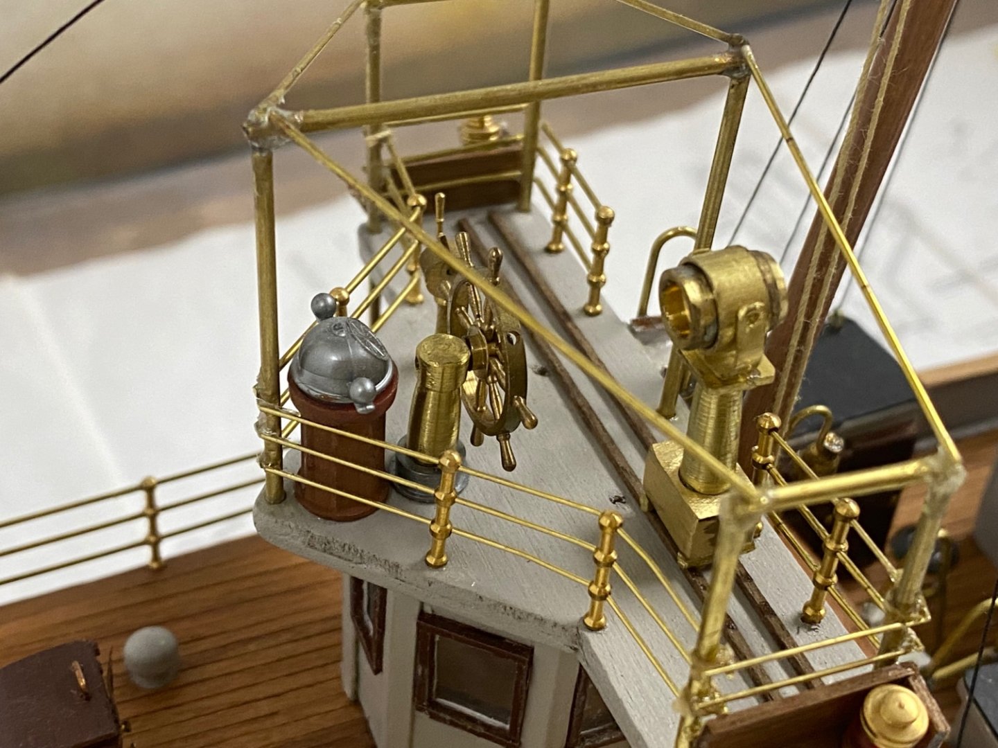
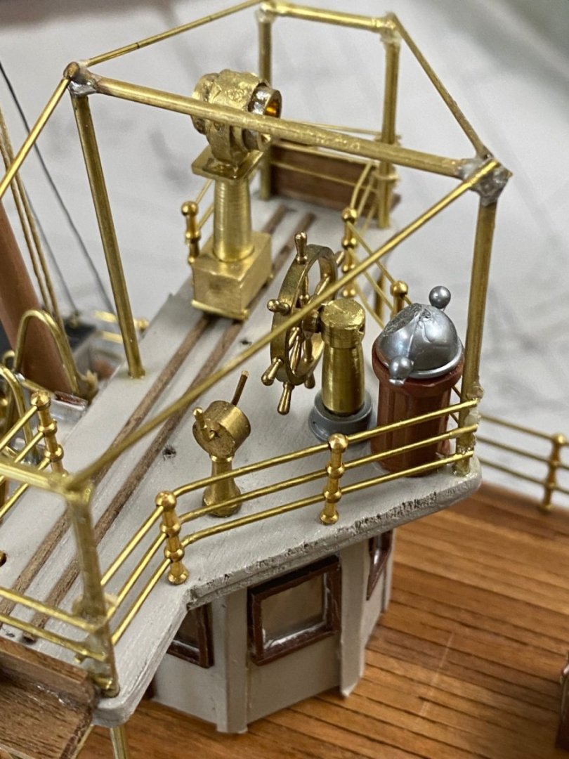
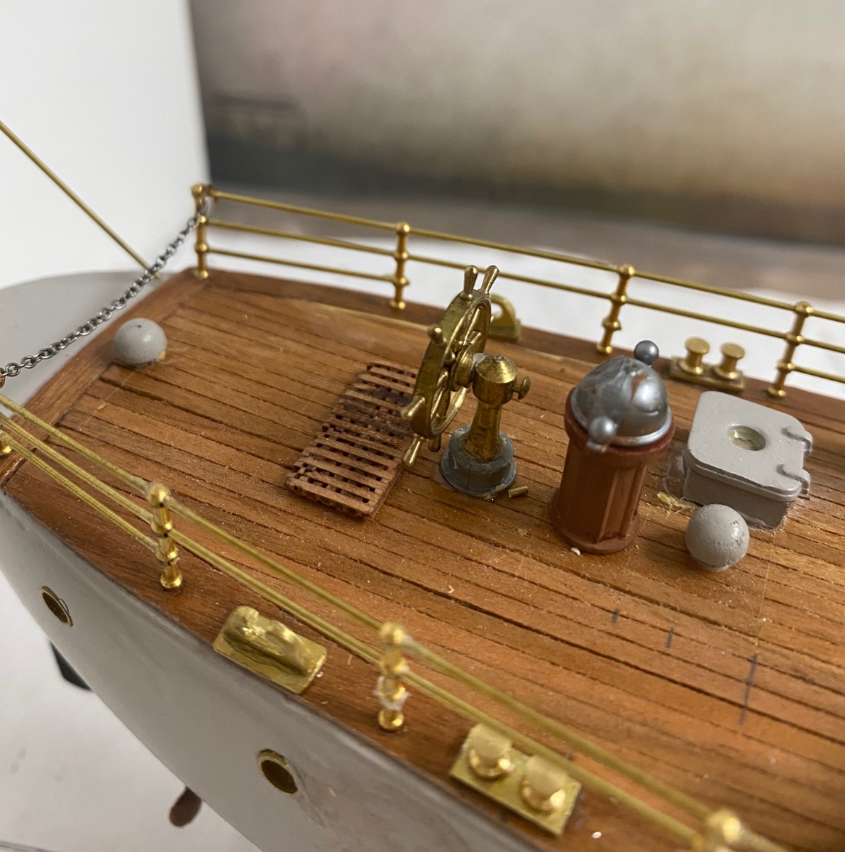
And finished the work on the forecastle.
The work remaining now is to complete the ladders to the midship deck, the dinghy details and the boat's davits. Finalizing the show with the remaining railings aft.
- GrandpaPhil, wefalck, robdurant and 6 others
-
9
-
-
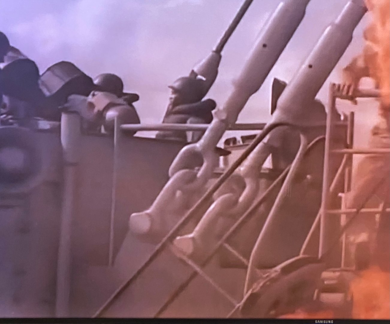
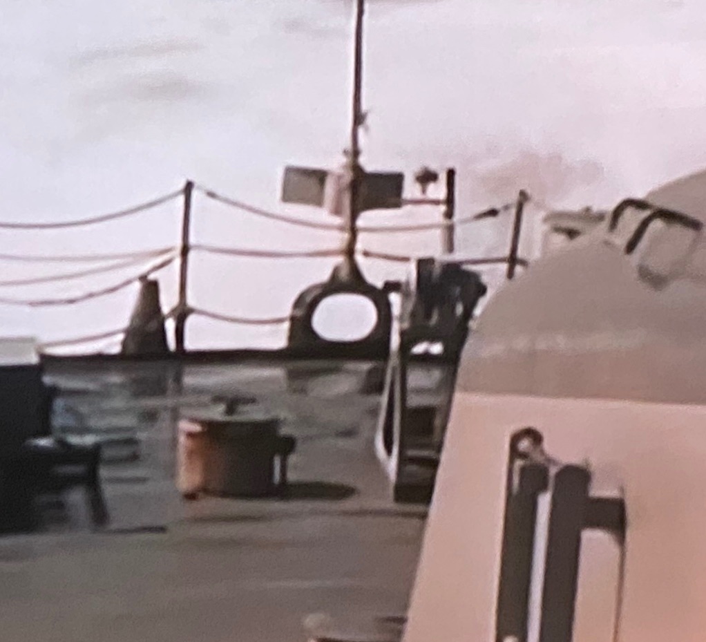
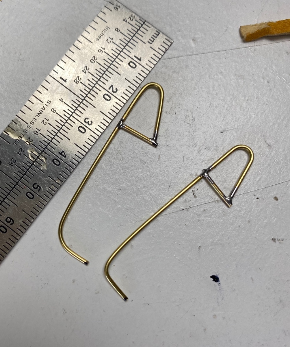
After I completed the fabrication of the ladders I was still trying to figure out how to transition the ladder handrails to the deck rails. The other night, while watching an old movie named "Away all Boats", I noted that the ladder handrails were independent of the deck rails as seen on the following screen shot.
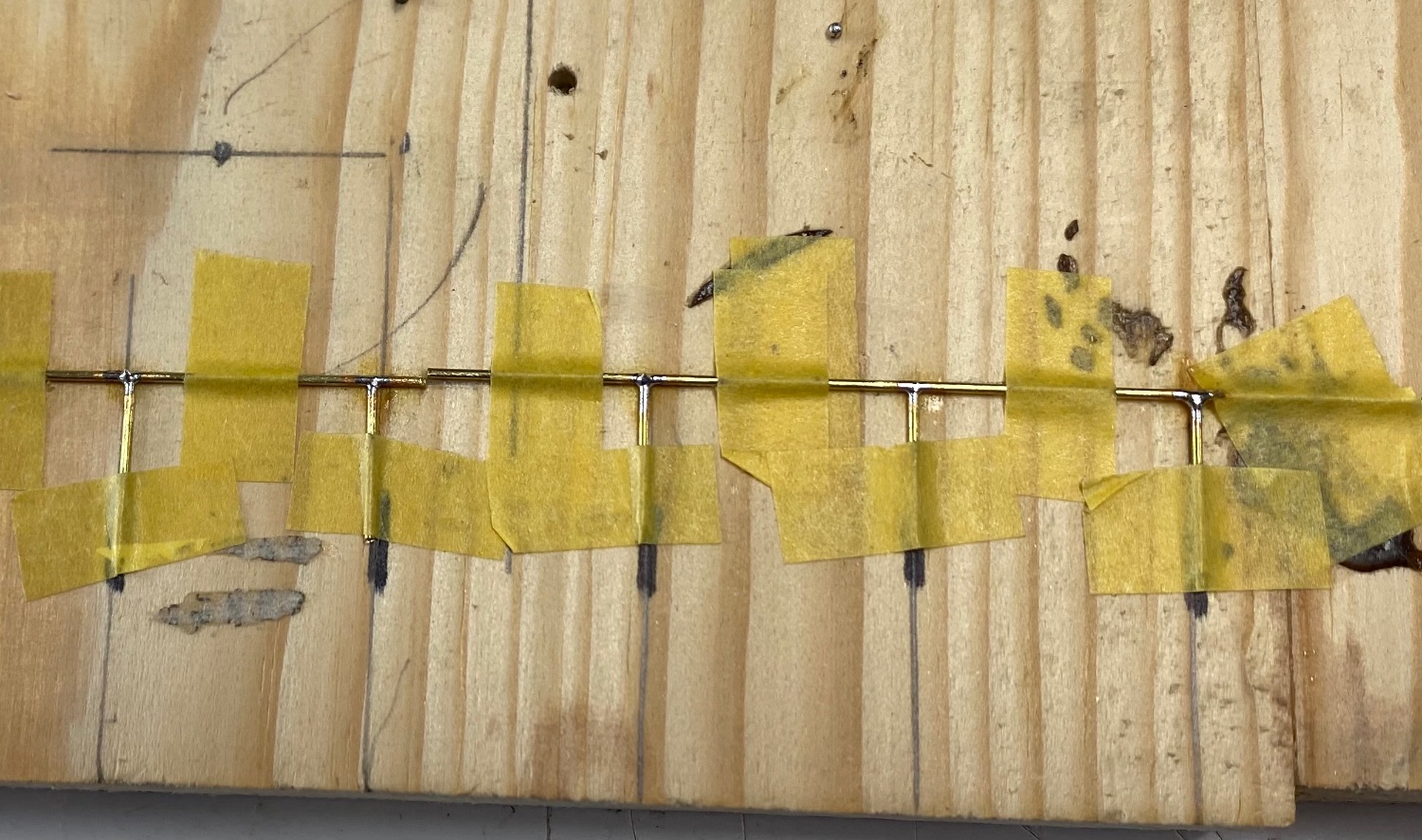
I made a jig to bend the wires and decided, again, to try my hand at soldering. I have read a lot of articles and suddenly had an epiphany. What I was doing wrong was to heat the joint and then tried to melt the solder into the joint. One of the comments I read was to set the solder on the tip of the welding gun and then transfer it to the fluxed joint. Worked like a charm.
The jig:
The finished product:
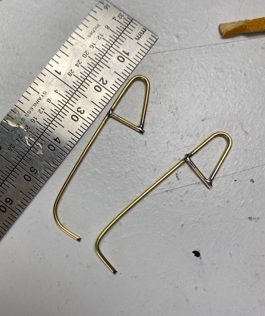
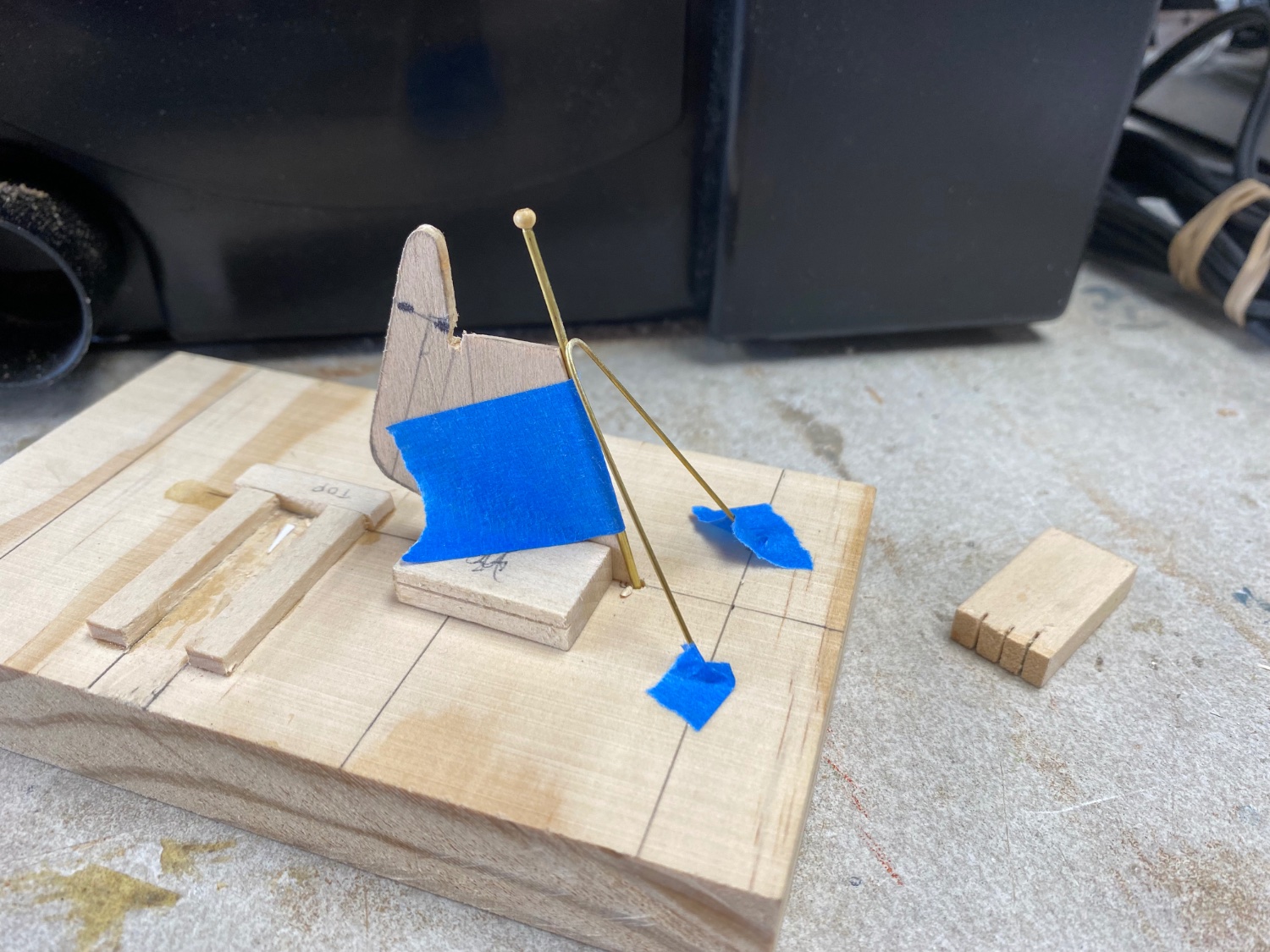
The same procedure was used to make the fantail flag staff.

-
Well, well well. I am thrilled at the response that y'all had on my ships boat building. I want to thank each and everyone of you for your support.
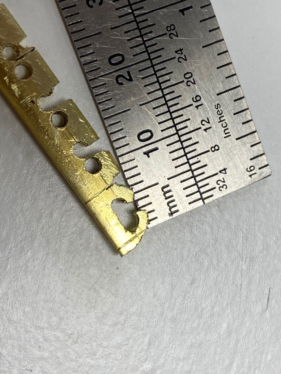
To mcb: Yes, the material I used for the fairways was 1/4"X1/16" brass bar available at Ace's hardware stores. My biggest problem on this item was to get four of them the same size. Later I realize I could have made the fairways easier with an elliptical hole as shown in the photo.
To Bob: good advise. Will try the tissue paper route and the saran wrap ideas. As a matter of fact, my first thought for these boats was to make them out of "papier-mache". Besides, this, being my first scratch built, is a testing and learning project.
To Valeriy: again thanks for your comments. The photo of the stocking under tension is great.
To Wefalk: I have been following you "ships boat" building and found it fascinating. Your idea to show the boats under cover is very accurate in the real boats and saves innumerable hours of detailing for the interior at small scales. I will probably do it on the two large boats on Amapá and detail the little dinghy.
To Roger: again thanks for you comments and I will be looking for your tutorial on NRG. Like I said before, this model is my scratch build education.
- mtaylor, wefalck, GrandpaPhil and 1 other
-
4
-
Glad to hear you are well. Your little boat is precious. I am close to that to doing a similar job on my Amapá.
- mtaylor, Keith Black, mbp521 and 2 others
-
5
-
Thanks to Roger for the advise and to Valeriy for the re-tweet.
- Keith Black, mtaylor and Valeriy V
-
3
-
I proceeded with the idea of making the ships boats out of reinforced resin. I made the molds and and finished them with three coats of shellac with fine sanding in between. When properly dried, I applied carnauba wax to the mold in two layers. Then using the hose stocking's material, provided by the Admiral, I applied the resin.
I tried to smooth it out the best I could and left it to dry 24 hours.

Then catastrophe!!!
As I tried to remove the hull from the mold parts of the hull where still adhering to the mold and I could nor get a clean casting.
I will rest for a while and figure it out. Initially I think that my mold release was not sufficient, that I should have trimmed the cloth more around the mold and that, perhaps should use two layers. I would appreciate your comments and suggestions.
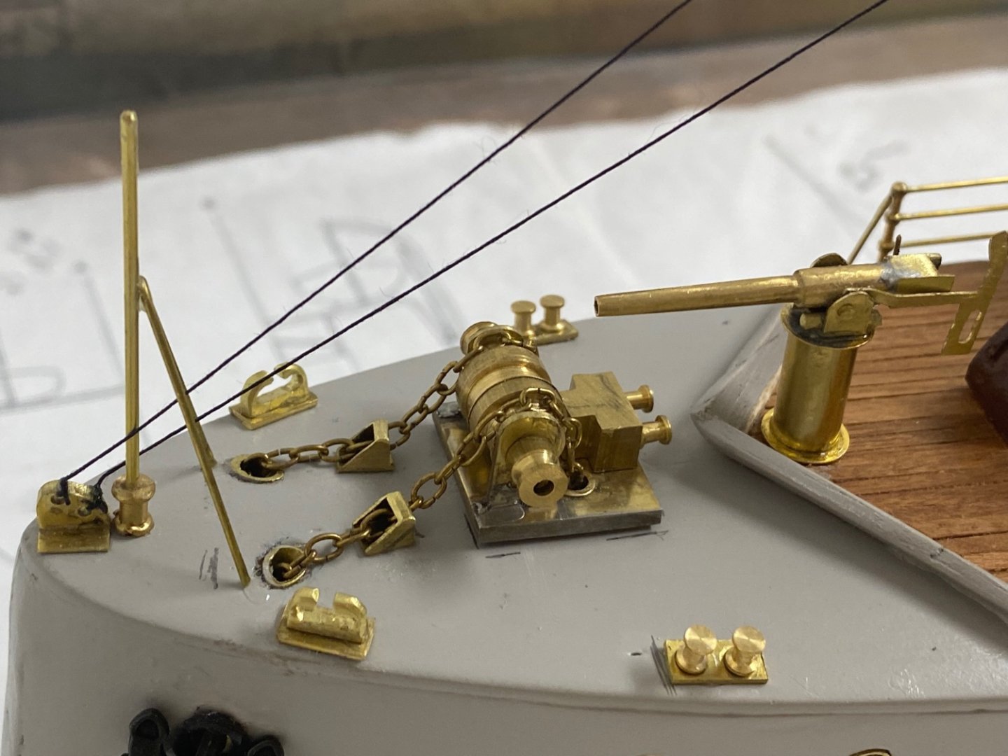
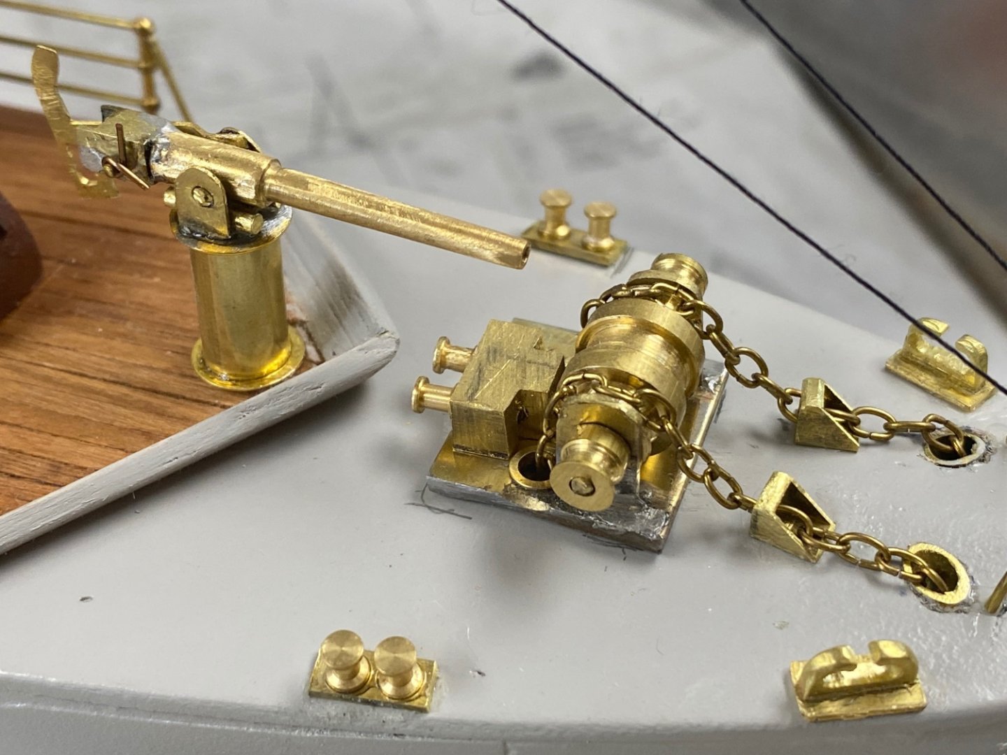
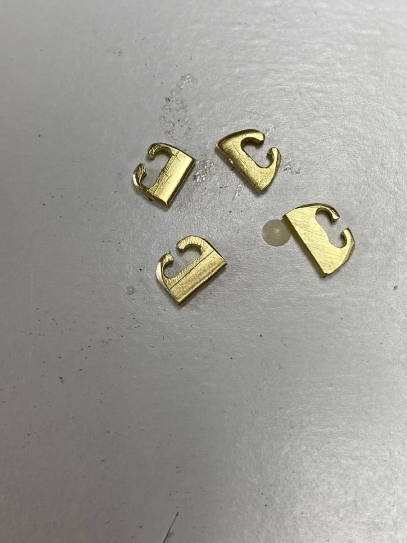
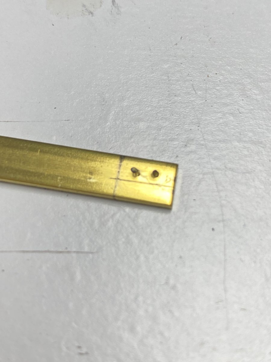
But still more remains to be fabricated. The finished bollards need their fairleads. Following is the method I used:
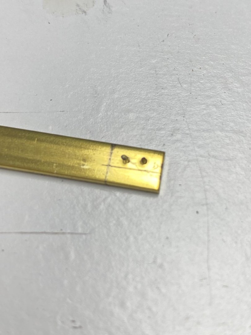
After drilling two holes in line I carved the fairlead shape with jewelers files

And this is the result. Success
All I need now is to make the other three I need, reduce their height a bit and glue them their bases.
Now the cold beer is waiting. Another day in the life of a model boat builder.
-
Glad to hear you are Ok. The cutter looks great. Saturday I epoxied the little dingy for. Amapa. Hope it comes out well.
- mtaylor, Keith Black and FriedClams
-
3
-
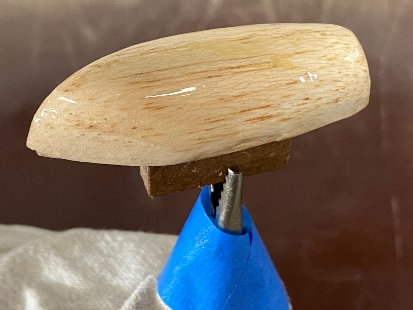
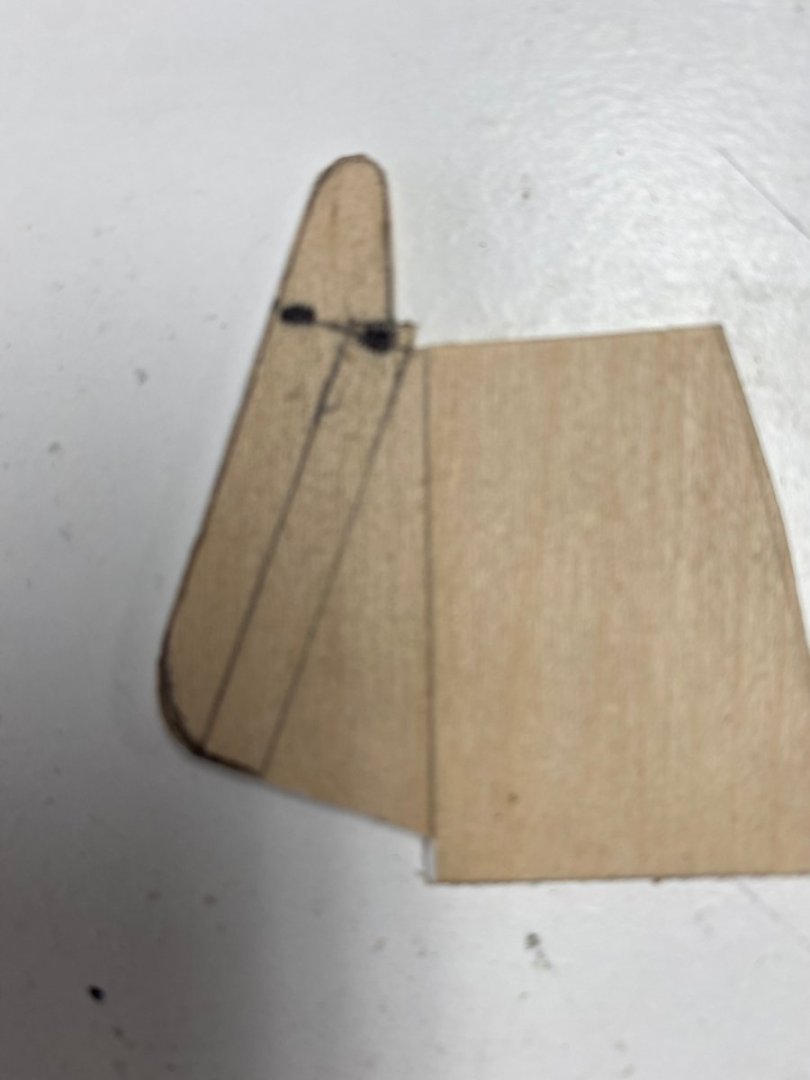
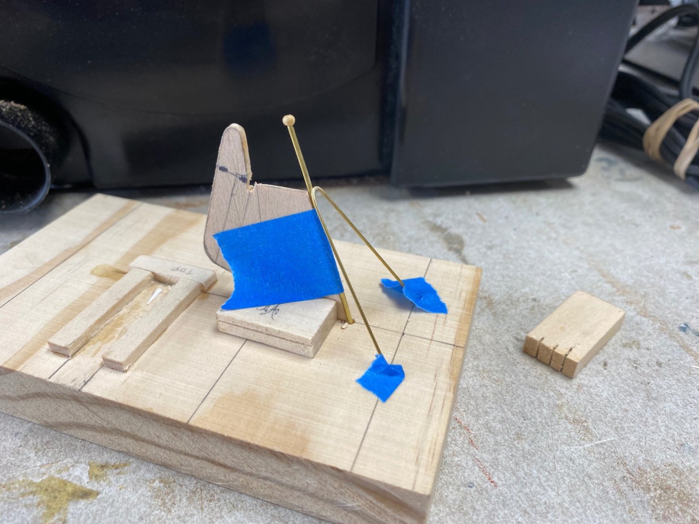
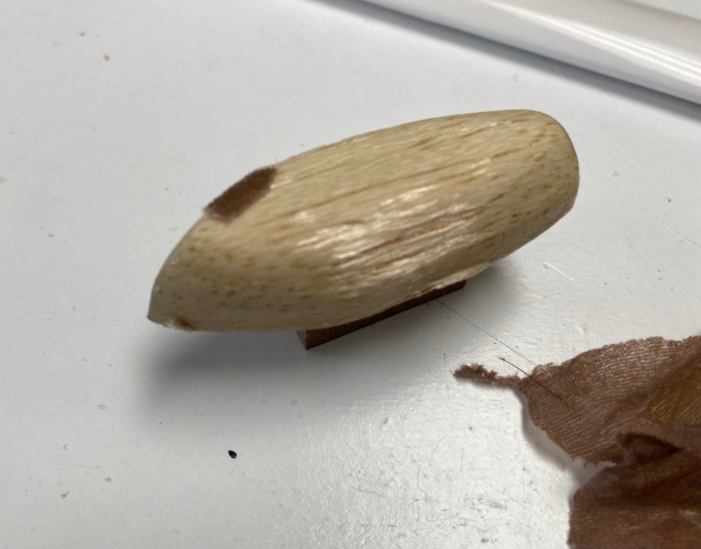
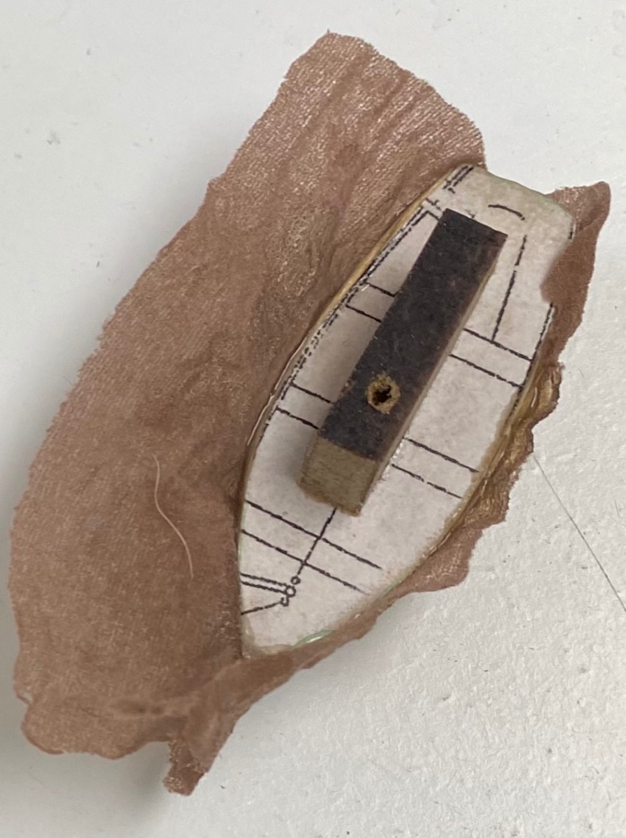
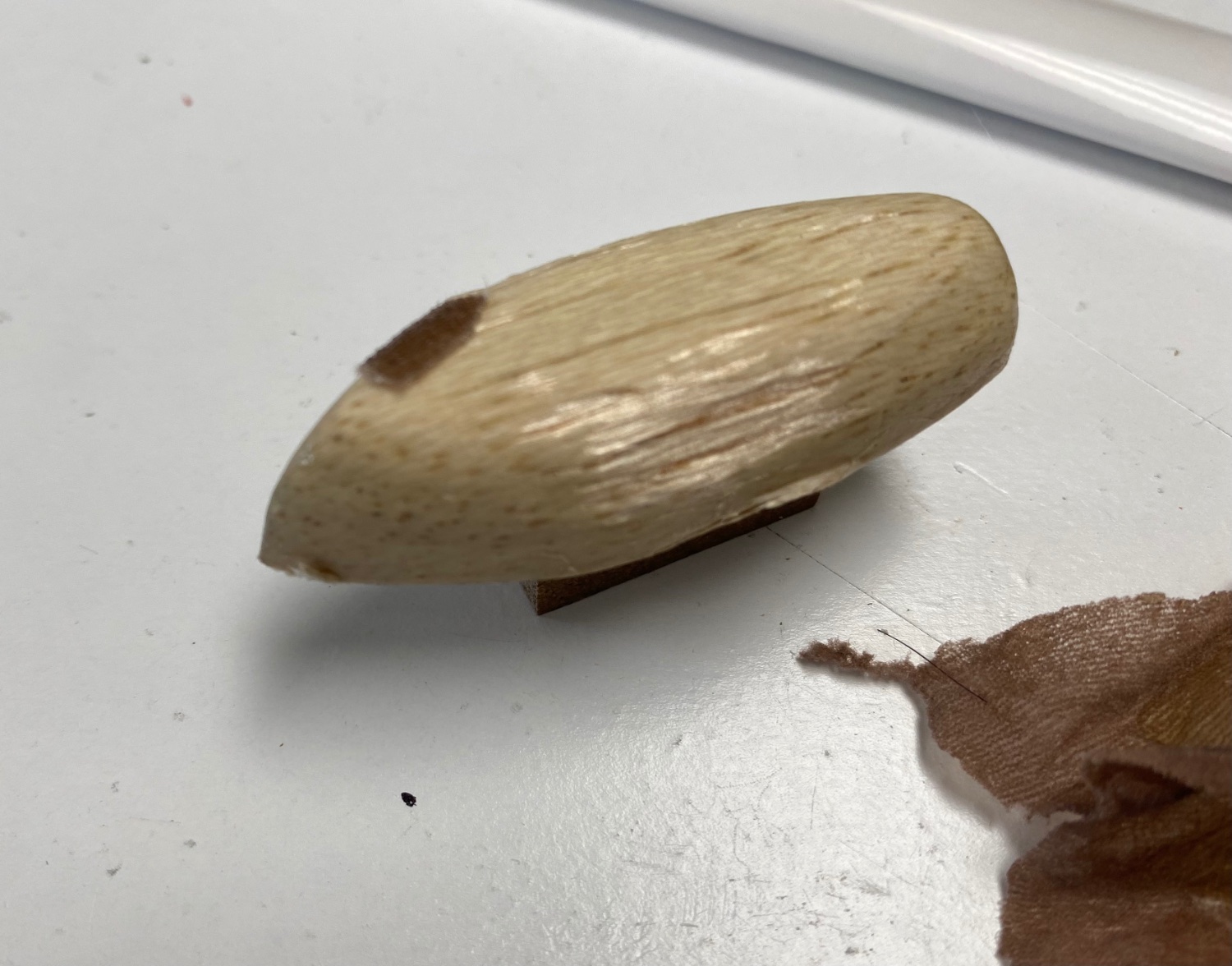
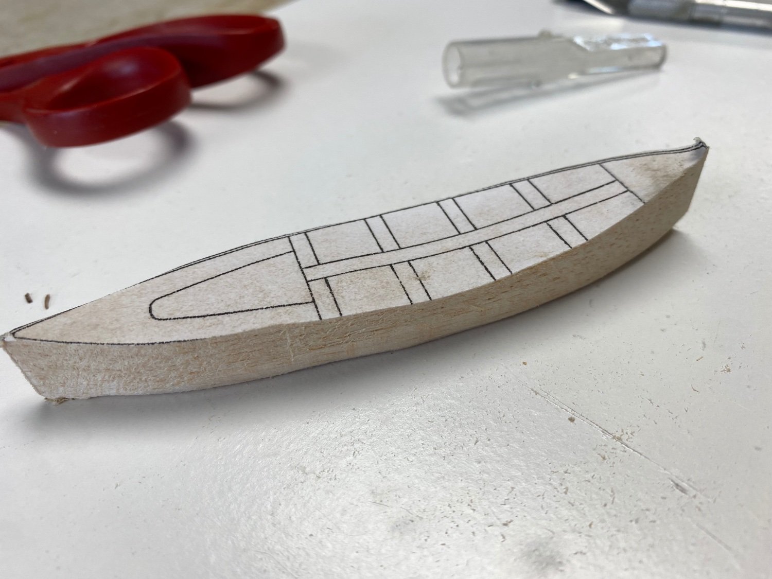
My next challenge were the ship's boats. Three of them. Today I stated picking out what to use for the mold. I had oak, mahogany and balsa. After much though, I figure that balsa would be easier for the carving so I cut a block of balsa, pasted the top and side plans of the first boat, a whaler. Then I proceeded to cut out the shapes and following is the results
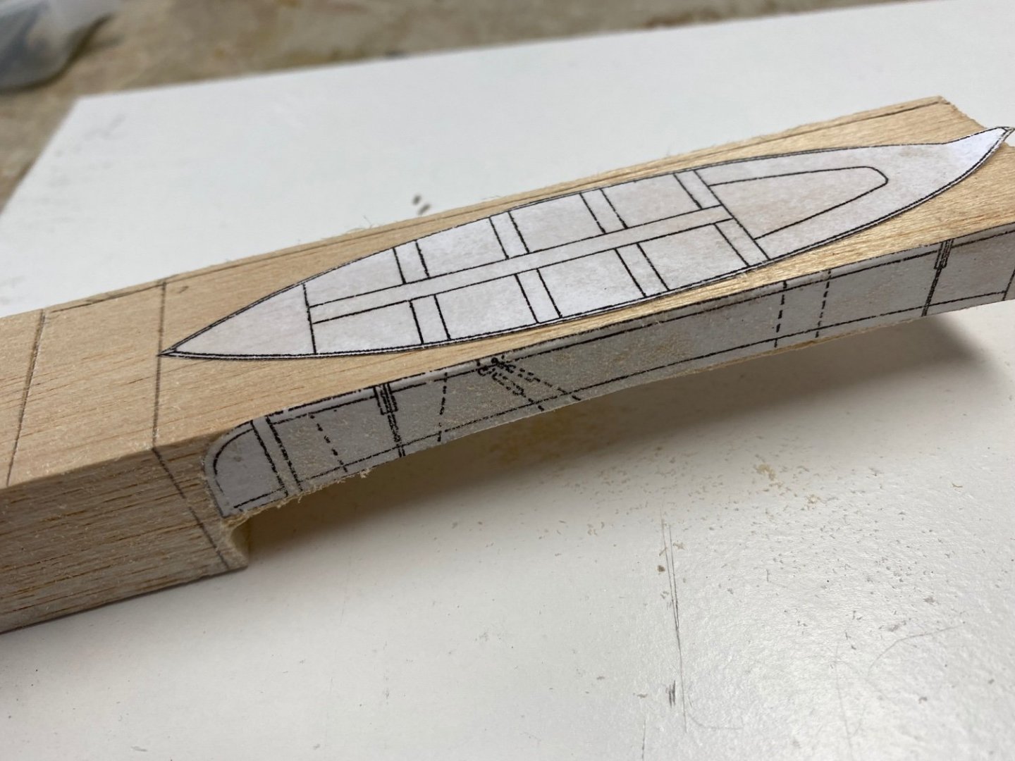


I sealed the mold with polyurethane and added a small tab to the bottom to allow holding the mold in the vise.
Now I have to wait for the Admiral (she is out of town) to get a used panty hose to make the first boat. I can't believe that I did all this in one morning while it took me close two weeks to complete the ladders. More to follow.
- mtaylor, bruce d, GrandpaPhil and 3 others
-
6


HMS MIMI 1915 by Ras Ambrioso - FINISHED - Scale 1:24 - Fast Motor Launch
in - Build logs for subjects built 1901 - Present Day
Posted
Being working on a simile of the petrol engines. The following photo shows the various parts built.
The crankcase, transmission and starting crank support.
Cylinders, and cylinder head housings.
The engine being assembled.
The starter cranks.
And finally the engine dry fitted to the boat.
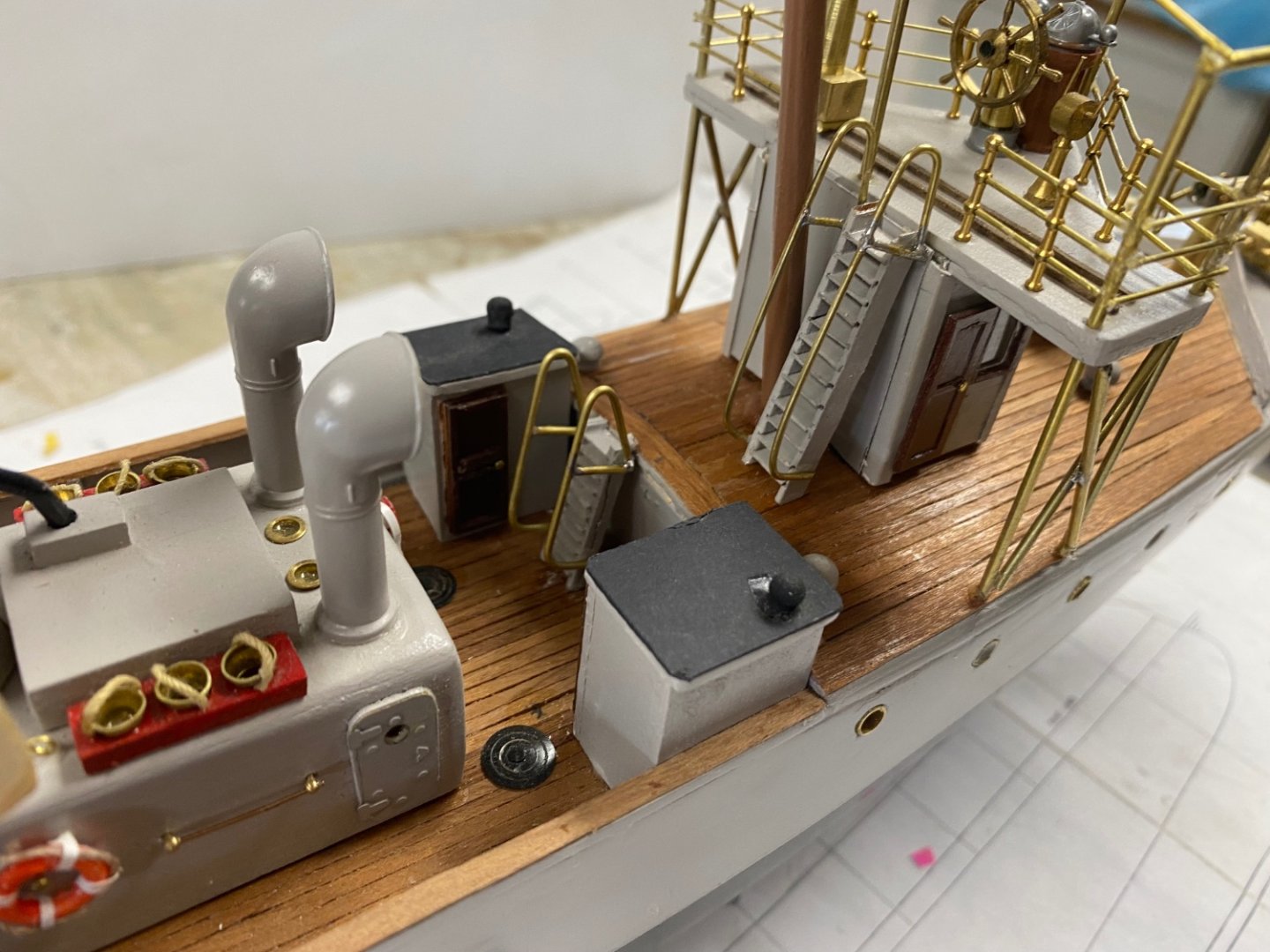
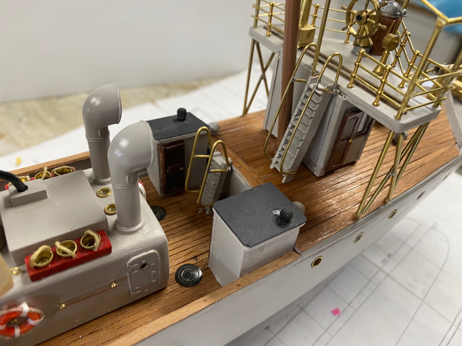
I also installed the fore and aft sub-decks with the marked accessories
I am now researching the engine attachments such as carburetor, magneto, plugs, intake and exhaust manifolds. Most of these will not be visible once the cabin roof is in place but, I thought that the engine would not be complete without them. I am having a lot of fun researching and figuring out what to use to represent these items.
Thanks to all you for the likes and comments.